Page 1746 of 2493
SBR768E
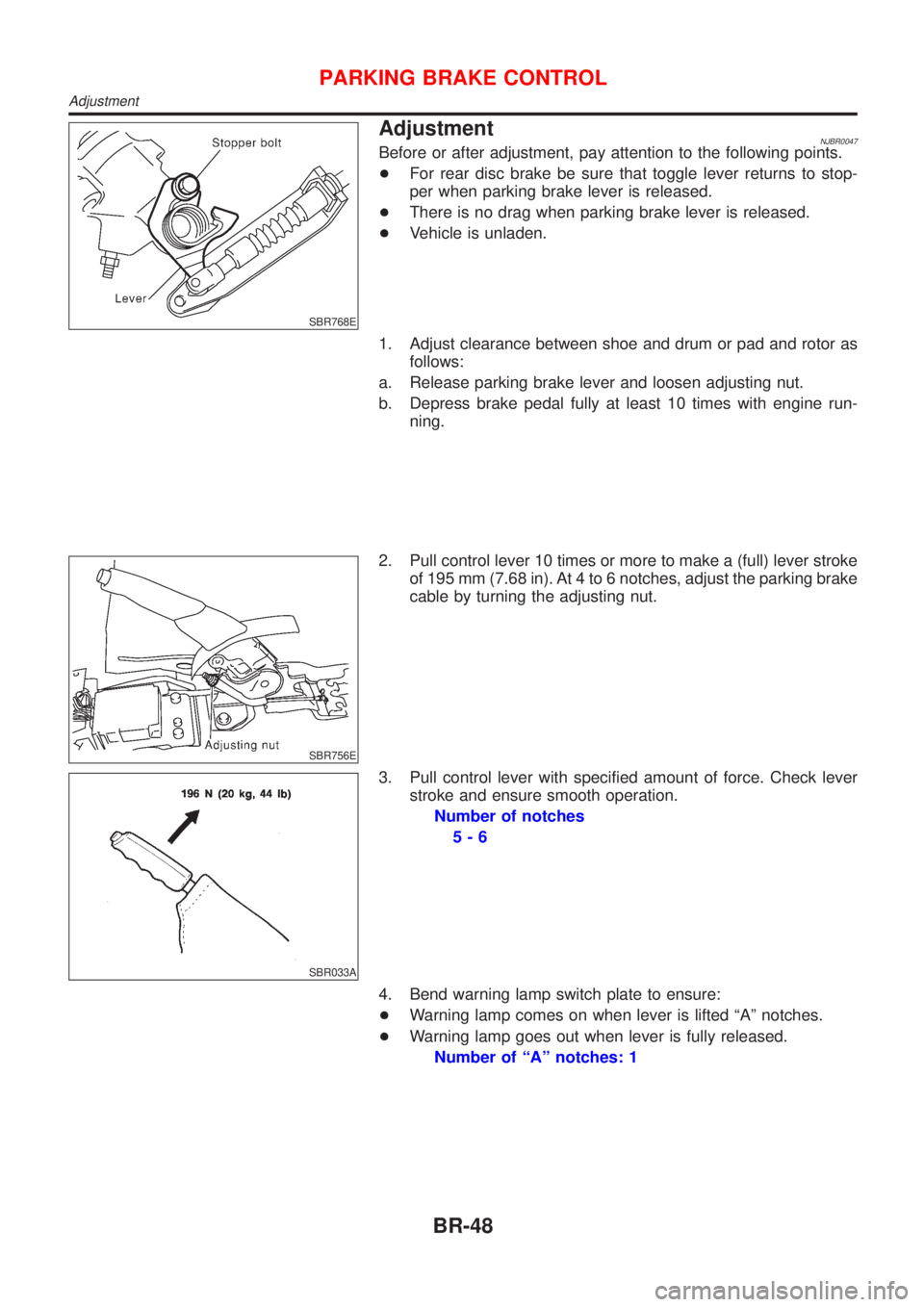
AdjustmentNJBR0047Before or after adjustment, pay attention to the following points.
+For rear disc brake be sure that toggle lever returns to stop-
per when parking brake lever is released.
+There is no drag when parking brake lever is released.
+Vehicle is unladen.
1. Adjust clearance between shoe and drum or pad and rotor as
follows:
a. Release parking brake lever and loosen adjusting nut.
b. Depress brake pedal fully at least 10 times with engine run-
ning.
SBR756E
2. Pull control lever 10 times or more to make a (full) lever stroke
of 195 mm (7.68 in). At 4 to 6 notches, adjust the parking brake
cable by turning the adjusting nut.
SBR033A
3. Pull control lever with specified amount of force. Check lever
stroke and ensure smooth operation.
Number of notches
5-6
4. Bend warning lamp switch plate to ensure:
+Warning lamp comes on when lever is lifted ªAº notches.
+Warning lamp goes out when lever is fully released.
Number of ªAº notches: 1
PARKING BRAKE CONTROL
Adjustment
BR-48
Page 1748 of 2493
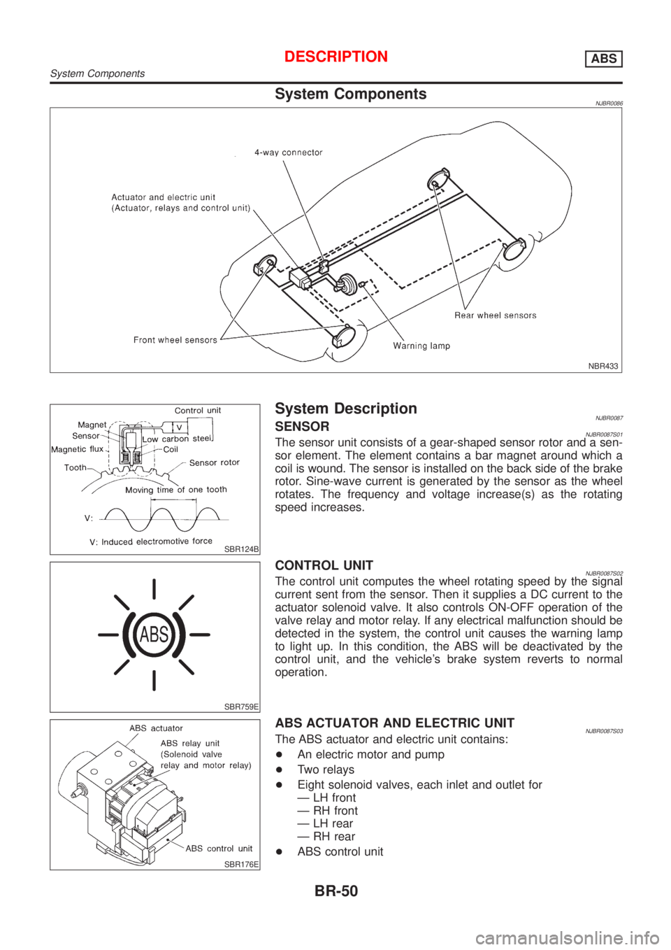
System ComponentsNJBR0086
NBR433
SBR124B
System DescriptionNJBR0087SENSORNJBR0087S01The sensor unit consists of a gear-shaped sensor rotor and a sen-
sor element. The element contains a bar magnet around which a
coil is wound. The sensor is installed on the back side of the brake
rotor. Sine-wave current is generated by the sensor as the wheel
rotates. The frequency and voltage increase(s) as the rotating
speed increases.
SBR759E
CONTROL UNITNJBR0087S02The control unit computes the wheel rotating speed by the signal
current sent from the sensor. Then it supplies a DC current to the
actuator solenoid valve. It also controls ON-OFF operation of the
valve relay and motor relay. If any electrical malfunction should be
detected in the system, the control unit causes the warning lamp
to light up. In this condition, the ABS will be deactivated by the
control unit, and the vehicle's brake system reverts to normal
operation.
SBR176E
ABS ACTUATOR AND ELECTRIC UNITNJBR0087S03The ABS actuator and electric unit contains:
+An electric motor and pump
+Two relays
+Eight solenoid valves, each inlet and outlet for
Ð LH front
Ð RH front
Ð LH rear
Ð RH rear
+ABS control unit
DESCRIPTIONABS
System Components
BR-50
Page 1756 of 2493
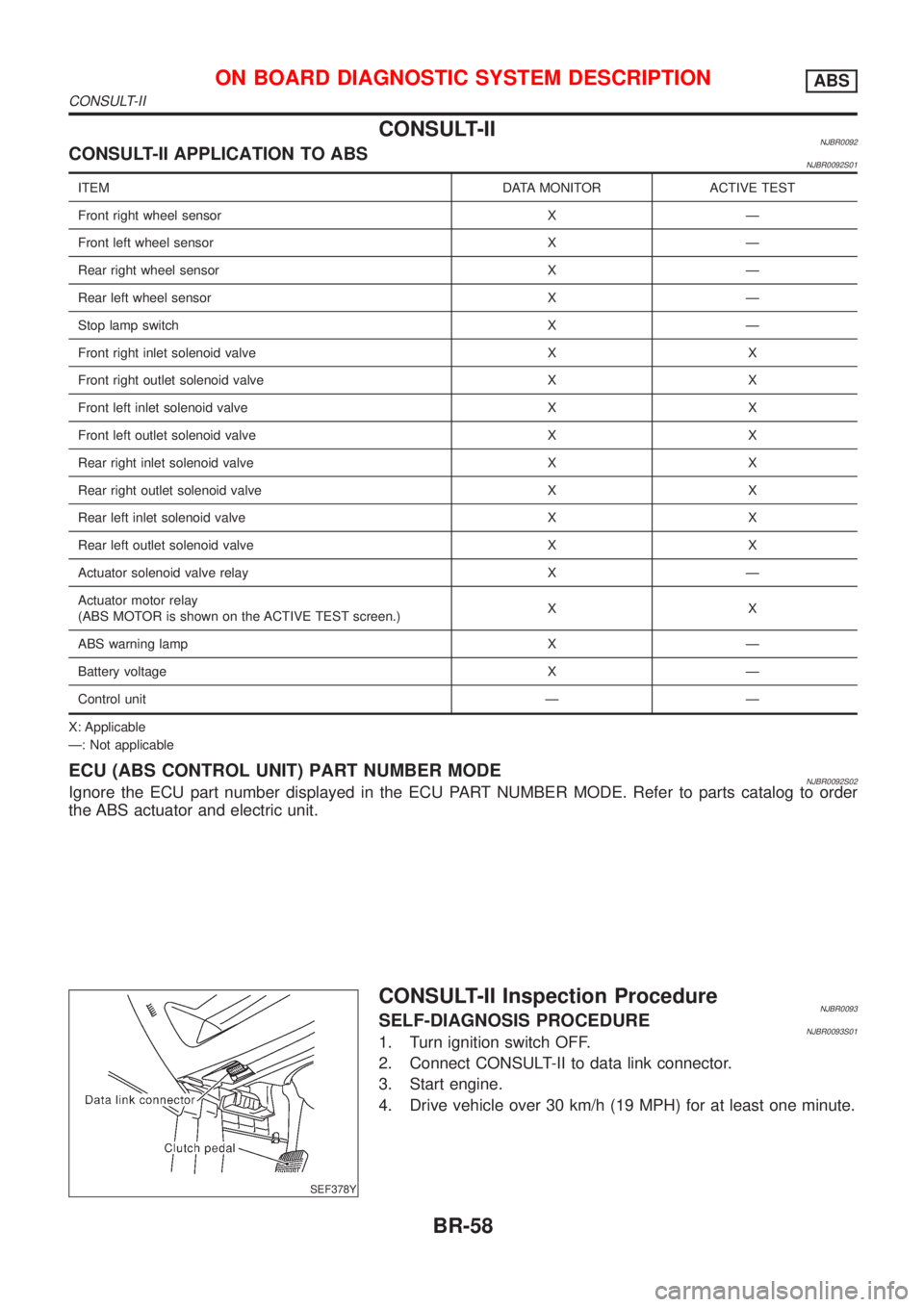
CONSULT-IINJBR0092CONSULT-II APPLICATION TO ABSNJBR0092S01
ITEM DATA MONITOR ACTIVE TEST
Front right wheel sensor X Ð
Front left wheel sensor X Ð
Rear right wheel sensor X Ð
Rear left wheel sensor X Ð
Stop lamp switch X Ð
Front right inlet solenoid valve X X
Front right outlet solenoid valve X X
Front left inlet solenoid valve X X
Front left outlet solenoid valve X X
Rear right inlet solenoid valve X X
Rear right outlet solenoid valve X X
Rear left inlet solenoid valve X X
Rear left outlet solenoid valve X X
Actuator solenoid valve relay X Ð
Actuator motor relay
(ABS MOTOR is shown on the ACTIVE TEST screen.)XX
ABS warning lamp X Ð
Battery voltage X Ð
Control unit Ð Ð
X: Applicable
Ð: Not applicable
ECU (ABS CONTROL UNIT) PART NUMBER MODENJBR0092S02Ignore the ECU part number displayed in the ECU PART NUMBER MODE. Refer to parts catalog to order
the ABS actuator and electric unit.
SEF378Y
CONSULT-II Inspection ProcedureNJBR0093SELF-DIAGNOSIS PROCEDURENJBR0093S011. Turn ignition switch OFF.
2. Connect CONSULT-II to data link connector.
3. Start engine.
4. Drive vehicle over 30 km/h (19 MPH) for at least one minute.
ON BOARD DIAGNOSTIC SYSTEM DESCRIPTIONABS
CONSULT-II
BR-58
Page 1759 of 2493
![NISSAN ALMERA N16 2001 Electronic Repair Manual Diagnostic item Diagnostic item is detected when ...Reference
Page
RR RH OUT ABS SOL
[SHORT]+Circuit for rear right outlet solenoid valve is shorted.
(An abnormally high output voltage is entered.)BR- NISSAN ALMERA N16 2001 Electronic Repair Manual Diagnostic item Diagnostic item is detected when ...Reference
Page
RR RH OUT ABS SOL
[SHORT]+Circuit for rear right outlet solenoid valve is shorted.
(An abnormally high output voltage is entered.)BR-](/manual-img/5/57351/w960_57351-1758.png)
Diagnostic item Diagnostic item is detected when ...Reference
Page
RR RH OUT ABS SOL
[SHORT]+Circuit for rear right outlet solenoid valve is shorted.
(An abnormally high output voltage is entered.)BR-72
RR LH OUT ABS SOL
[SHORT]+Circuit for rear left outlet solenoid valve is shorted.
(An abnormally high output voltage is entered.)BR-72
ABS ACTUATOR RELAY
[ABNORMAL]+Actuator solenoid valve relay is ON, even control unit sends off signal.
+Actuator solenoid valve relay is OFF, even control unit sends on signal.BR-72
ABS MOTOR RELAY
[ABNORMAL]+Circuit for actuator motor is open or shorted.
+Actuator motor relay is stuck.BR-75
BATTERY VOLT
[ABNORMAL]+Power source voltage supplied to ABS control unit is abnormally low. BR-77
CONTROL UNIT+Function of calculation in ABS control unit has failed. BR-79
*1: Be sure to confirm the ABS warning lamp illuminates when the ignition switch is turned ON after repairing the shorted sensor circuit,
but the lamp goes out when driving the vehicle over 30 km/h (19 MPH) for one minute in accordance with SELF-DIAGNOSIS
PROCEDURE.
PBR455D
DATA MONITOR PROCEDURENJBR0093S031. Turn ignition switch OFF.
2. Connect CONSULT-II to data link connector.
3. Turn ignition switch ON.
4. Touch ªSTARTº on CONSULT-II screen.
PBR385C
5. Touch ªABSº.
PST412B
6. Touch ªDATA MONITORº.
7. Touch ªSETTINGº on ªSELECT MONITOR ITEMº screen.
8. Touch ªLONG TIMEº on ªSET RECORDING CONDº screen.
9. Touch ªSTARTº on ªSELECT MONITOR ITEMº.
ON BOARD DIAGNOSTIC SYSTEM DESCRIPTIONABS
CONSULT-II Inspection Procedure (Cont'd)
BR-61
Page 1767 of 2493
Wheel Sensor or RotorNJBR0098DIAGNOSTIC PROCEDURENJBR0098S01
1 INSPECTION START
Wheel sensor inspection
SBR476EB
©GO TO 2.
2 CHECK CONNECTOR
1. Disconnect connectors from control unit and wheel sensor according to the self-diagnostic results. Check terminals for
damage or loose connections. Then reconnect connectors.
2. Carry out self-diagnosis again.
Does warning lamp activate again?
Ye s©GO TO 3.
No©INSPECTION END
3 CHECK WHEEL SENSOR CIRCUIT
1. Disconnect control unit connector.
2. Check resistance between control unit connector terminals.
Code No. 21 or 22 (Front RH wheel)
Terminals 4 and 5
Code No. 25 or 26 (Front LH wheel)
Terminals 6 and 7
Code No. 31 or 32 (Rear RH wheel)
Terminals 1 and 3
Code No. 35 or 36 (Rear LH wheel)
Terminals 8 and 9
Resistance: 1.44 - 1.76 kW
SBR477EC
Is resistance 1.44 - 1.76 kW?
Ye s©GO TO 5.
No©GO TO 4.
TROUBLE DIAGNOSES FOR SELF-DIAGNOSTIC ITEMSABS
Wheel Sensor or Rotor
BR-69
Page 1778 of 2493
1. ABS Works FrequentlyNJBR0104
1 CHECK BRAKE FLUID PRESSURE
Check brake fluid pressure distribution.
Is brake fluid pressure distribution normal?
Ye s©GO TO 2.
No©Perform Preliminary Check. Refer to BR-65.
2 CHECK WHEEL SENSOR
1. Check wheel sensor connector for terminal damage or loose connections.
2. Perform wheel sensor mechanical check.
Refer to ªWheel Sensor or Rotorº, BR-69.
Are wheel sensors functioning properly?
Ye s©GO TO 3.
No©Repair.
3 CHECK FRONT AXLE
Check front and rear axles for excessive looseness. Refer to AX section, ªFront Wheel Bearingº, ªON-VEHICLE SERVICEº
and ªRear Wheel Bearingº, ªON-VEHICLE SERVICEº.
Is front axle installed properly?
Ye s©Go to ª3. CHECK WARNING LAMP INDICATIONº in ª2. Unexpected Pedal Actionº,
BR-81.
No©Repair.
2. Unexpected Pedal ActionNJBR0105
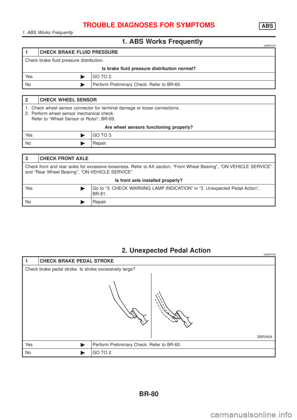
1 CHECK BRAKE PEDAL STROKE
Check brake pedal stroke. Is stroke excessively large?
SBR540A
Ye s©Perform Preliminary Check. Refer to BR-65.
No©GO TO 2.
TROUBLE DIAGNOSES FOR SYMPTOMSABS
1. ABS Works Frequently
BR-80
Page 1853 of 2493
SRS825
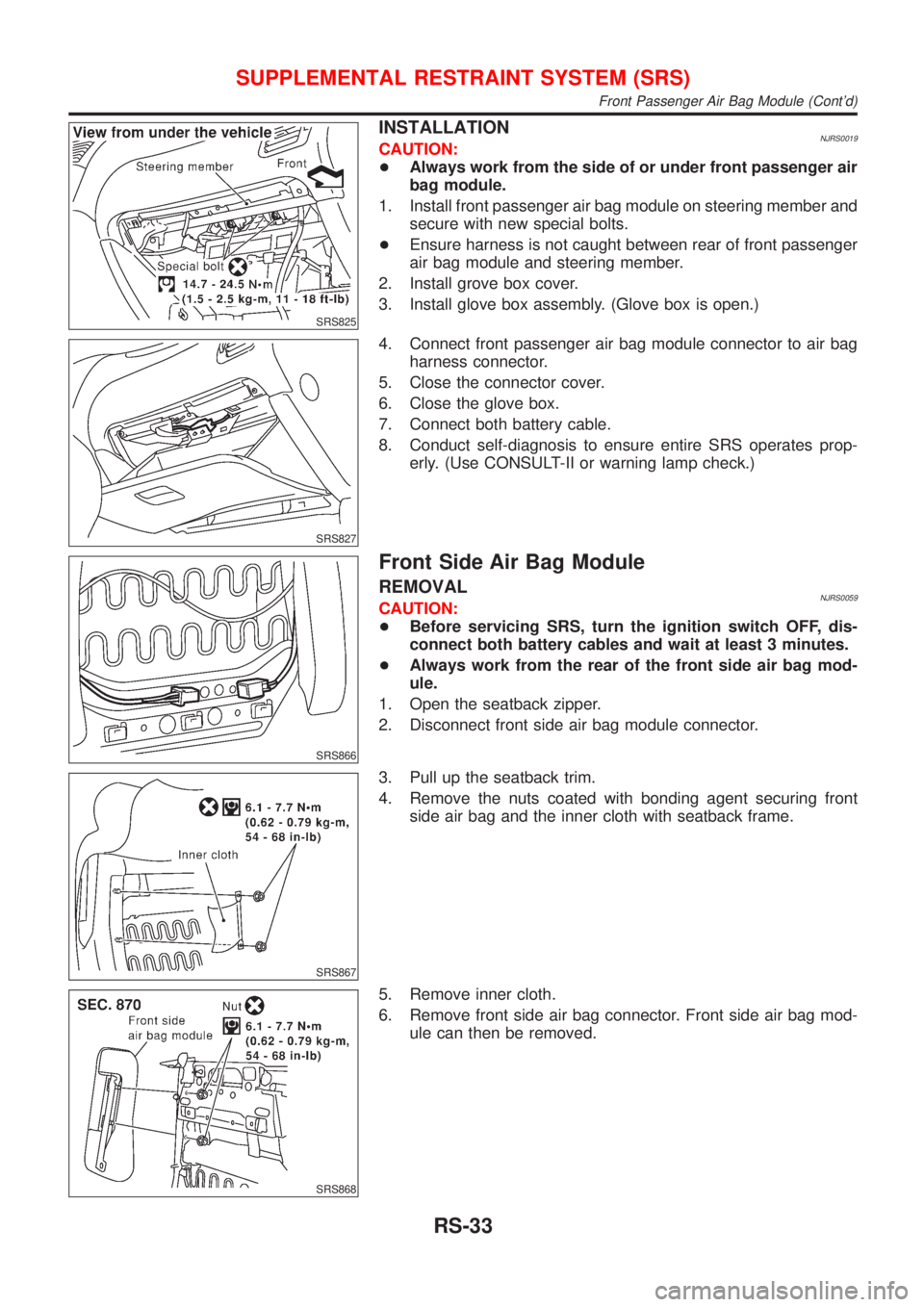
INSTALLATIONNJRS0019CAUTION:
+Always work from the side of or under front passenger air
bag module.
1. Install front passenger air bag module on steering member and
secure with new special bolts.
+Ensure harness is not caught between rear of front passenger
air bag module and steering member.
2. Install grove box cover.
3. Install glove box assembly. (Glove box is open.)
SRS827
4. Connect front passenger air bag module connector to air bag
harness connector.
5. Close the connector cover.
6. Close the glove box.
7. Connect both battery cable.
8. Conduct self-diagnosis to ensure entire SRS operates prop-
erly. (Use CONSULT-II or warning lamp check.)
SRS866
Front Side Air Bag Module
REMOVALNJRS0059CAUTION:
+Before servicing SRS, turn the ignition switch OFF, dis-
connect both battery cables and wait at least 3 minutes.
+Always work from the rear of the front side air bag mod-
ule.
1. Open the seatback zipper.
2. Disconnect front side air bag module connector.
SRS867
3. Pull up the seatback trim.
4. Remove the nuts coated with bonding agent securing front
side air bag and the inner cloth with seatback frame.
SRS868
5. Remove inner cloth.
6. Remove front side air bag connector. Front side air bag mod-
ule can then be removed.
SUPPLEMENTAL RESTRAINT SYSTEM (SRS)
Front Passenger Air Bag Module (Cont'd)
RS-33
Page 1925 of 2493
Removal and InstallationNJBT0013SEDANNJBT0013S01CAUTION:
+Wrap the tip of flat-bladed screwdriver with a cloth when removing metal clips from garnishes.
1. Remove front and rear seats. Refer to ªFRONT SEATº and ªREAR SEATº for details, BT-56 and BT-59.
2. Remove front and rear seat belts. Refer to RS-5 and RS-11, ªFront Seat Beltº and ªRear Seat Beltº for
details.
3. Remove front and rear outer kicking plates.
4. Remove front and rear inner kicking plates.
5. Remove dash side finishers.
6. Remove front and rear body side welts.
7. Remove front pillar garnishes.
8. Remove center pillar lower garnishes.
9. Remove center pillar upper garnishes.
10. Remove rear seat back finishers.
11. Remove rear pillar finishers.
12. Remove high-mounted stop lamp. (Models without rear air spoiler)
13. Remove seat back center and side finishers.
14. Remove rear parcel shelf finisher.
15. Remove hoot rest.
16. Remove floor carpet.
SIDE AND FLOOR TRIM
Removal and Installation
BT-31