Page 1289 of 2493
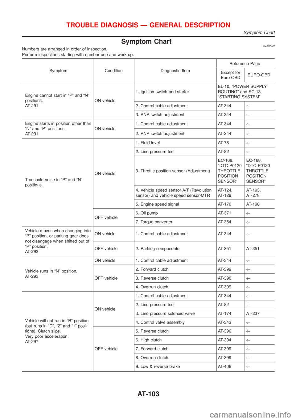
Symptom ChartNJAT0029Numbers are arranged in order of inspection.
Perform inspections starting with number one and work up.
Symptom Condition Diagnostic ItemReference Page
Except for
Euro-OBDEURO-OBD
Engine cannot start in ªPº and ªNº
positions.
AT-291ON vehicle1. Ignition switch and starterEL-10, ªPOWER SUPPLY
ROUTINGº and SC-13,
ªSTARTING SYSTEMº
2. Control cable adjustment AT-344¬
3. PNP switch adjustment AT-344¬
Engine starts in position other than
ªNº and ªPº positions.
AT-291ON vehicle1. Control cable adjustment AT-344¬
2. PNP switch adjustment AT-344¬
Transaxle noise in ªPº and ªNº
positions.ON vehicle1. Fluid level AT-78¬
2. Line pressure test AT-82¬
3. Throttle position sensor (Adjustment)EC-168,
ªDTC P0120
THROTTLE
POSITION
SENSORºEC-168,
ªDTC P0120
THROTTLE
POSITION
SENSORº
4. Vehicle speed sensor´A/T (Revolution
sensor) and vehicle speed sensor´MTRAT-124,
AT-129AT-193,
AT-278
5. Engine speed signal AT-170 AT-198
OFF vehicle6. Oil pump AT-371¬
7. Torque converter AT-354¬
Vehicle moves when changing into
ªPº position, or parking gear does
not disengage when shifted out of
ªPº position.
AT-292ON vehicle 1. Control cable adjustment AT-344¬
OFF vehicle 2. Parking components AT-351 AT-351
Vehicle runs in ªNº position.
AT-293ON vehicle 1. Control cable adjustment AT-344¬
OFF vehicle2. Forward clutch AT-399¬
3. Reverse clutch AT-390¬
4. Overrun clutch AT-399¬
Vehicle will not run in ªRº position
(but runs in ªDº, ª2º and ª1º posi-
tions). Clutch slips.
Very poor acceleration.
AT-297ON vehicle1. Control cable adjustment AT-344¬
2. Line pressure test AT-82¬
3. Line pressure solenoid valve AT-174 AT-237
4. Control valve assembly AT-343¬
OFF vehicle5. Reverse clutch AT-390¬
6. High clutch AT-394¬
7. Forward clutch AT-399¬
8. Overrun clutch AT-399¬
9. Low & reverse brake AT-406¬
TROUBLE DIAGNOSIS Ð GENERAL DESCRIPTION
Symptom Chart
AT-103
Page 1291 of 2493
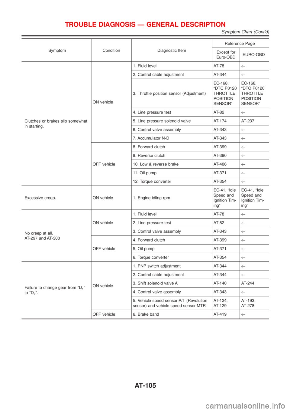
Symptom Condition Diagnostic ItemReference Page
Except for
Euro-OBDEURO-OBD
Clutches or brakes slip somewhat
in starting.ON vehicle1. Fluid level AT-78¬
2. Control cable adjustment AT-344¬
3. Throttle position sensor (Adjustment)EC-168,
ªDTC P0120
THROTTLE
POSITION
SENSORºEC-168,
ªDTC P0120
THROTTLE
POSITION
SENSORº
4. Line pressure test AT-82¬
5. Line pressure solenoid valve AT-174 AT-237
6. Control valve assembly AT-343¬
7. Accumulator N-D AT-343¬
OFF vehicle8. Forward clutch AT-399¬
9. Reverse clutch AT-390¬
10. Low & reverse brake AT-406¬
11. Oil pump AT-371¬
12. Torque converter AT-354¬
Excessive creep. ON vehicle 1. Engine idling rpmEC-41, ªIdle
Speed and
Ignition Tim-
ingºEC-41, ªIdle
Speed and
Ignition Tim-
ingº
No creep at all.
AT-297 and AT-300ON vehicle1. Fluid level AT-78¬
2. Line pressure test AT-82¬
3. Control valve assembly AT-343¬
OFF vehicle4. Forward clutch AT-399¬
5. Oil pump AT-371¬
6. Torque converter AT-354¬
Failure to change gear from ªD
1º
to ªD
2º.ON vehicle1. PNP switch adjustment AT-344¬
2. Control cable adjustment AT-344¬
3. Shift solenoid valve A AT-140 AT-244
4. Control valve assembly AT-343¬
5. Vehicle speed sensor´A/T (Revolution
sensor) and vehicle speed sensor´MTRAT-124,
AT-129AT-193,
AT-278
OFF vehicle 6. Brake band AT-419¬
TROUBLE DIAGNOSIS Ð GENERAL DESCRIPTION
Symptom Chart (Cont'd)
AT-105
Page 1300 of 2493
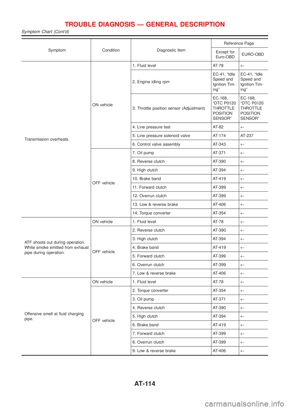
Symptom Condition Diagnostic ItemReference Page
Except for
Euro-OBDEURO-OBD
Transmission overheats.ON vehicle1. Fluid level AT-78¬
2. Engine idling rpmEC-41, ªIdle
Speed and
Ignition Tim-
ingºEC-41, ªIdle
Speed and
Ignition Tim-
ingº
3. Throttle position sensor (Adjustment)EC-168,
ªDTC P0120
THROTTLE
POSITION
SENSORºEC-168,
ªDTC P0120
THROTTLE
POSITION
SENSORº
4. Line pressure test AT-82¬
5. Line pressure solenoid valve AT-174 AT-237
6. Control valve assembly AT-343¬
OFF vehicle7. Oil pump AT-371¬
8. Reverse clutch AT-390¬
9. High clutch AT-394¬
10. Brake band AT-419¬
11. Forward clutch AT-399¬
12. Overrun clutch AT-399¬
13. Low & reverse brake AT-406¬
14. Torque converter AT-354¬
ATF shoots out during operation.
White smoke emitted from exhaust
pipe during operation.ON vehicle 1. Fluid level AT-78¬
OFF vehicle2. Reverse clutch AT-390¬
3. High clutch AT-394¬
4. Brake band AT-419¬
5. Forward clutch AT-399¬
6. Overrun clutch AT-399¬
7. Low & reverse brake AT-406¬
Offensive smell at fluid charging
pipe.ON vehicle 1. Fluid level AT-78¬
OFF vehicle2. Torque converter AT-354¬
3. Oil pump AT-371¬
4. Reverse clutch AT-390¬
5. High clutch AT-394¬
6. Brake band AT-419¬
7. Forward clutch AT-399¬
8. Overrun clutch AT-399¬
9. Low & reverse brake AT-406¬
TROUBLE DIAGNOSIS Ð GENERAL DESCRIPTION
Symptom Chart (Cont'd)
AT-114
Page 1346 of 2493
Diagnostic ProcedureNJAT0056
1 CHECK VALVE RESISTANCE
1. Turn ignition switch to ªOFFº position.
2. Disconnect terminal cord assembly connector in engine compartment.
3. Check resistance between terminal 5 and ground.
Resistance:
5-20W
SAT889JA
OK or NG
OK©GO TO 2.
NG©1. Remove oil pan. Refer to AT-343.
2. Check the following items:
+Torque converter clutch solenoid valve
Refer to ªComponent Inspectionº, AT-162.
+Harness of terminal cord assembly for short or open
TORQUE CONVERTER CLUTCH
SOLENOID VALVE
EXCEPT FOR EURO-OBD
Diagnostic Procedure
AT-160
Page 1353 of 2493
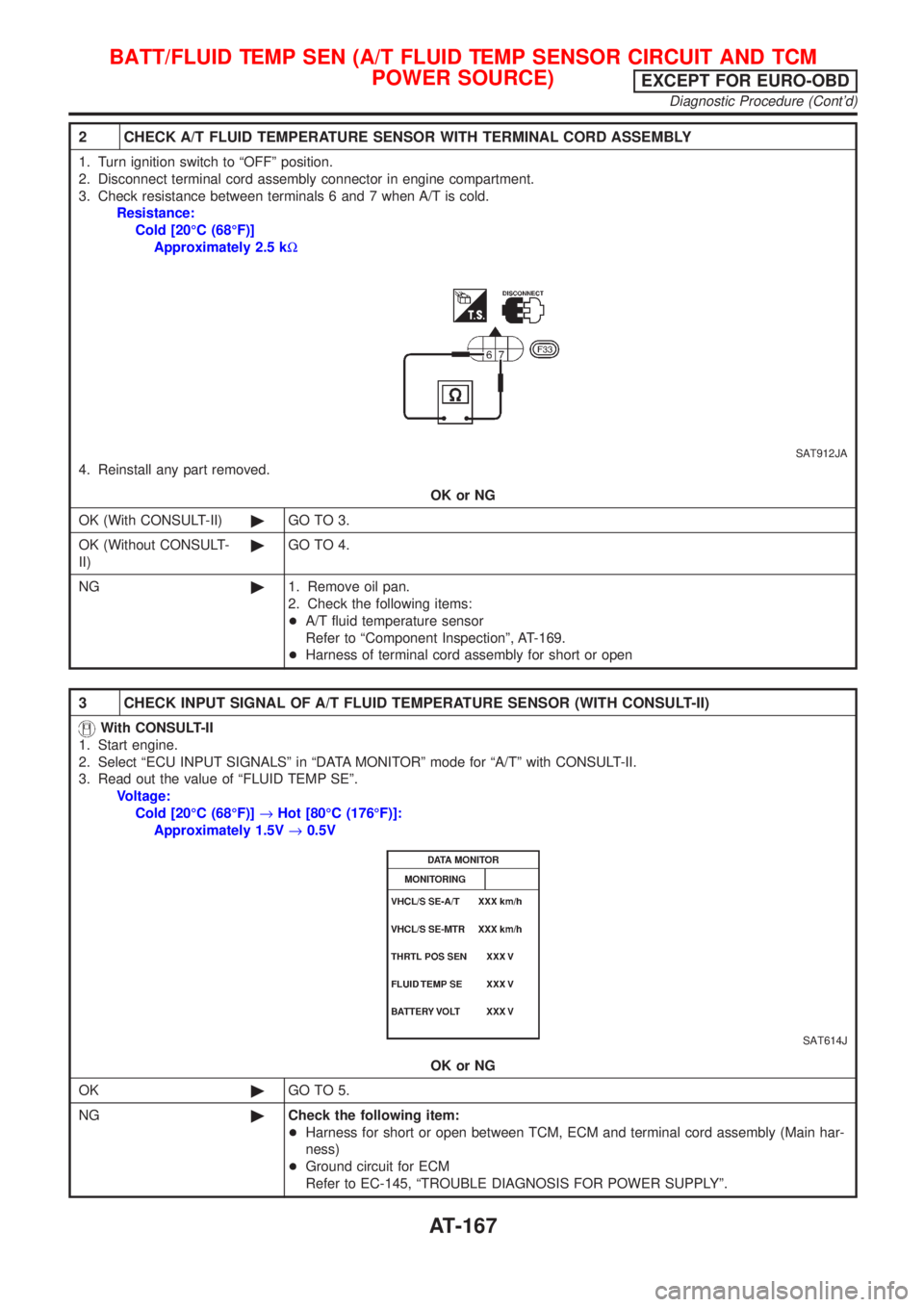
2 CHECK A/T FLUID TEMPERATURE SENSOR WITH TERMINAL CORD ASSEMBLY
1. Turn ignition switch to ªOFFº position.
2. Disconnect terminal cord assembly connector in engine compartment.
3. Check resistance between terminals 6 and 7 when A/T is cold.
Resistance:
Cold [20ÉC (68ÉF)]
Approximately 2.5 kW
SAT912JA
4. Reinstall any part removed.
OK or NG
OK (With CONSULT-II)©GO TO 3.
OK (Without CONSULT-
II)©GO TO 4.
NG©1. Remove oil pan.
2. Check the following items:
+A/T fluid temperature sensor
Refer to ªComponent Inspectionº, AT-169.
+Harness of terminal cord assembly for short or open
3 CHECK INPUT SIGNAL OF A/T FLUID TEMPERATURE SENSOR (WITH CONSULT-II)
With CONSULT-II
1. Start engine.
2. Select ªECU INPUT SIGNALSº in ªDATA MONITORº mode for ªA/Tº with CONSULT-II.
3. Read out the value of ªFLUID TEMP SEº.
Voltage:
Cold [20ÉC (68ÉF)]®Hot [80ÉC (176ÉF)]:
Approximately 1.5V®0.5V
SAT614J
OK or NG
OK©GO TO 5.
NG©Check the following item:
+Harness for short or open between TCM, ECM and terminal cord assembly (Main har-
ness)
+Ground circuit for ECM
Refer to EC-145, ªTROUBLE DIAGNOSIS FOR POWER SUPPLYº.
BATT/FLUID TEMP SEN (A/T FLUID TEMP SENSOR CIRCUIT AND TCM
POWER SOURCE)
EXCEPT FOR EURO-OBD
Diagnostic Procedure (Cont'd)
AT-167
Page 1358 of 2493
Diagnostic ProcedureNJAT0042
1 CHECK DTC WITH ECM
Perform diagnostic test mode II (self-diagnostic results) for engine control. Check ignition signal circuit condition.
OK or NG
OK (With CONSULT-II)©GO TO 2.
OK (Without CONSULT-
II)©GO TO 3.
NG©Check ignition signal circuit for engine control. Refer to EC-451, ªIGNITION SIGNALº.
2 CHECK INPUT SIGNAL (With CONSULT-II)
With CONSULT-II
1. Start engine.
2. Select ªECU INPUT SIGNALSº in ªDATA MONITORº mode for ªA/Tº with CONSULT-II.
SAT580J
3. Read out the value of ªENGINE SPEEDº.
Check engine speed changes according to throttle position.
SAT645J
OK or NG
OK©GO TO 4.
NG©Check the following items:
+Harness for short or open between TCM and ECM
+Resistor and ignition coil
Refer to EC-451, ªIGNITION SIGNALº.
ENGINE SPEED SIGNALEXCEPT FOR EURO-OBD
Diagnostic Procedure
AT-172
Page 1359 of 2493
3 CHECK INPUT SIGNAL (Without CONSULT-II)
Without CONSULT-II
1. Start engine.
2. Check voltage between TCM terminal 39 and ground.
Voltage (Idle speed):
Refer to EC-489, ªIdle Speed and Ignition Timingº.
SAT424JA
OK or NG
OK©GO TO 4.
NG©Check the following items:
+Harness for short or open between TCM and ECM
+Resistor and ignition coil
Refer to EC-451, ªIGNITION SIGNALº.
4 CHECK DTC
Perform Self-diagnosis Code confirmation procedure, AT-170.
OK or NG
OK©INSPECTION END
NG©1. Perform TCM input/output signal inspection.
2. If NG, recheck TCM pin terminals for damage or loose connection with harness con-
nector.
ENGINE SPEED SIGNALEXCEPT FOR EURO-OBD
Diagnostic Procedure (Cont'd)
AT-173
Page 1360 of 2493
SAT283HC
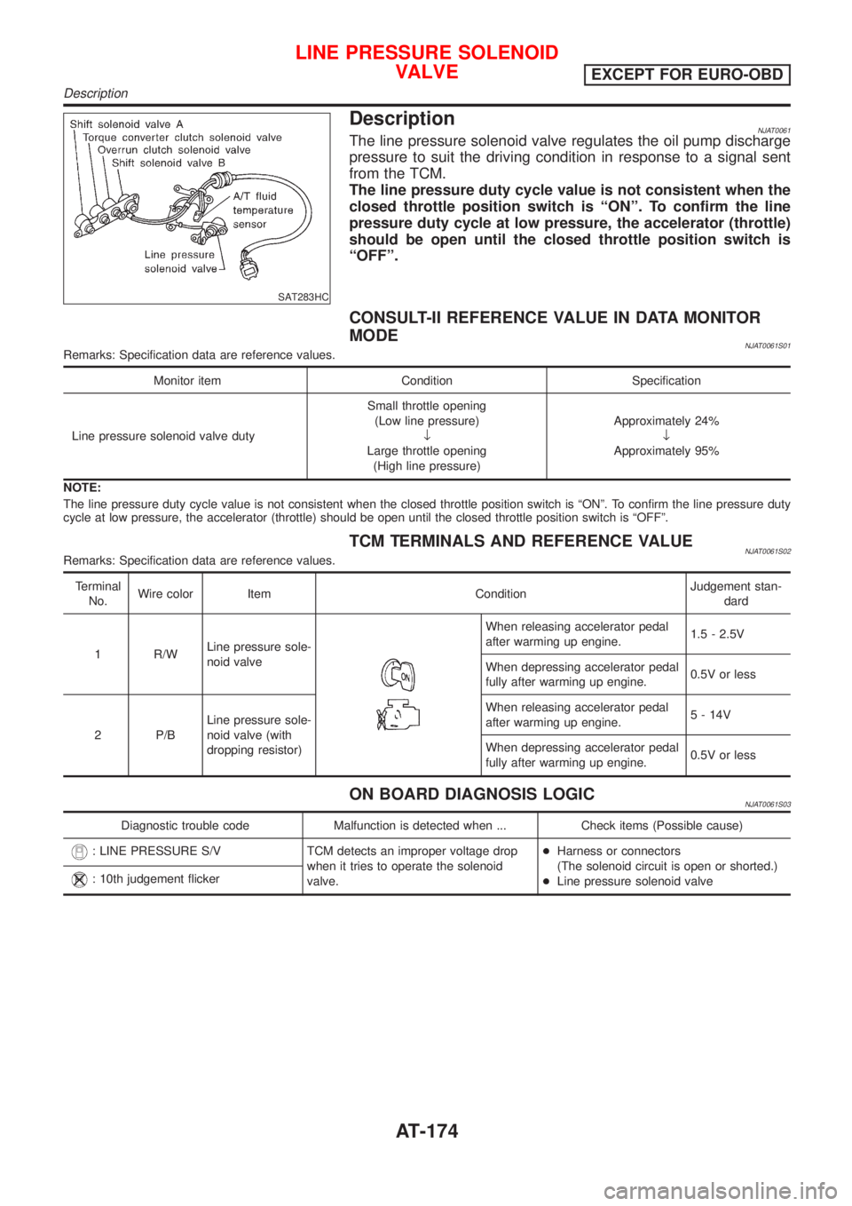
DescriptionNJAT0061The line pressure solenoid valve regulates the oil pump discharge
pressure to suit the driving condition in response to a signal sent
from the TCM.
The line pressure duty cycle value is not consistent when the
closed throttle position switch is ªONº. To confirm the line
pressure duty cycle at low pressure, the accelerator (throttle)
should be open until the closed throttle position switch is
ªOFFº.
CONSULT-II REFERENCE VALUE IN DATA MONITOR
MODE
NJAT0061S01Remarks: Specification data are reference values.
Monitor item Condition Specification
Line pressure solenoid valve dutySmall throttle opening
(Low line pressure)
¯
Large throttle opening
(High line pressure)Approximately 24%
¯
Approximately 95%
NOTE:
The line pressure duty cycle value is not consistent when the closed throttle position switch is ªONº. To confirm the line pressure duty
cycle at low pressure, the accelerator (throttle) should be open until the closed throttle position switch is ªOFFº.
TCM TERMINALS AND REFERENCE VALUENJAT0061S02Remarks: Specification data are reference values.
Terminal
No.Wire color Item ConditionJudgement stan-
dard
1 R/WLine pressure sole-
noid valve
When releasing accelerator pedal
after warming up engine.1.5 - 2.5V
When depressing accelerator pedal
fully after warming up engine.0.5V or less
2 P/BLine pressure sole-
noid valve (with
dropping resistor)When releasing accelerator pedal
after warming up engine.5 - 14V
When depressing accelerator pedal
fully after warming up engine.0.5V or less
ON BOARD DIAGNOSIS LOGICNJAT0061S03
Diagnostic trouble code Malfunction is detected when ... Check items (Possible cause)
: LINE PRESSURE S/V TCM detects an improper voltage drop
when it tries to operate the solenoid
valve.+Harness or connectors
(The solenoid circuit is open or shorted.)
+Line pressure solenoid valve
: 10th judgement flicker
LINE PRESSURE SOLENOID
VALVE
EXCEPT FOR EURO-OBD
Description
AT-174