2001 NISSAN ALMERA N16 engine oil
[x] Cancel search: engine oilPage 1065 of 2493
SMA067C
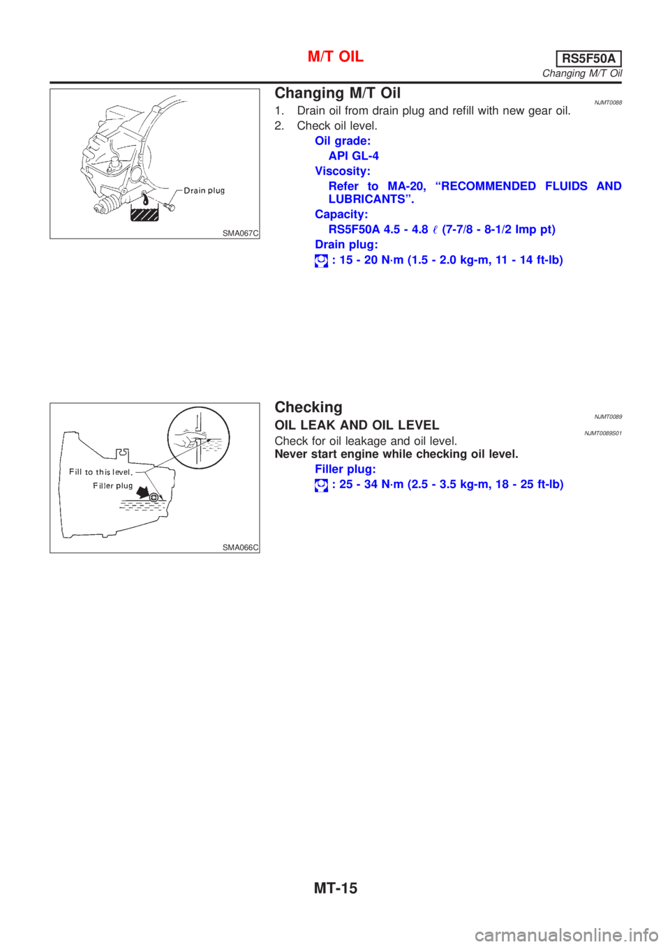
Changing M/T OilNJMT00881. Drain oil from drain plug and refill with new gear oil.
2. Check oil level.
Oil grade:
API GL-4
Viscosity:
Refer to MA-20, ªRECOMMENDED FLUIDS AND
LUBRICANTSº.
Capacity:
RS5F50A 4.5 - 4.8!(7-7/8 - 8-1/2 Imp pt)
Drain plug:
: 15 - 20 N´m (1.5 - 2.0 kg-m, 11 - 14 ft-lb)
SMA066C
CheckingNJMT0089OIL LEAK AND OIL LEVELNJMT0089S01Check for oil leakage and oil level.
Never start engine while checking oil level.
Filler plug:
: 25 - 34 N´m (2.5 - 3.5 kg-m, 18 - 25 ft-lb)
M/T OILRS5F50A
Changing M/T Oil
MT-15
Page 1073 of 2493
NJMT0008
SMT928D
RemovalNJMT0008S01CAUTION:
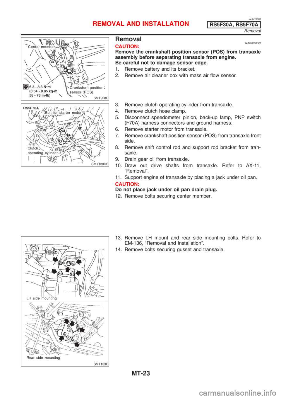
Remove the crankshaft position sensor (POS) from transaxle
assembly before separating transaxle from engine.
Be careful not to damage sensor edge.
1. Remove battery and its bracket.
2. Remove air cleaner box with mass air flow sensor.
SMT130DB
3. Remove clutch operating cylinder from transaxle.
4. Remove clutch hose clamp.
5. Disconnect speedometer pinion, back-up lamp, PNP switch
(F70A) harness connectors and ground harness.
6. Remove starter motor from transaxle.
7. Remove crankshaft position sensor (POS) from transaxle front
side.
8. Remove shift control rod and support rod bracket from tran-
saxle.
9. Drain gear oil from transaxle.
10. Draw out drive shafts from transaxle. Refer to AX-11,
ªRemovalº.
11. Support engine of transaxle by placing a jack under oil pan.
CAUTION:
Do not place jack under oil pan drain plug.
12. Remove bolts securing center member.
SMT133D
13. Remove LH mount and rear side mounting bolts. Refer to
EM-136, ªRemoval and Installationº.
14. Remove bolts securing gusset and transaxle.
REMOVAL AND INSTALLATIONRS5F30A, RS5F70A
Removal
MT-23
Page 1076 of 2493
NJMT0090
SMT928D
RemovalNJMT0090S01CAUTION:
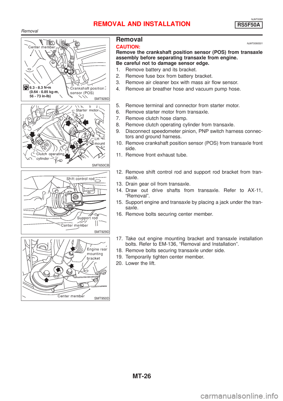
Remove the crankshaft position sensor (POS) from transaxle
assembly before separating transaxle from engine.
Be careful not to damage sensor edge.
1. Remove battery and its bracket.
2. Remove fuse box from battery bracket.
3. Remove air cleaner box with mass air flow sensor.
4. Remove air breather hose and vacuum pump hose.
SMT650CB
5. Remove terminal and connector from starter motor.
6. Remove starter motor from transaxle.
7. Remove clutch hose clamp.
8. Remove clutch operating cylinder from transaxle.
9. Disconnect speedometer pinion, PNP switch harness connec-
tors and ground harness.
10. Remove crankshaft position sensor (POS) from transaxle front
side.
11. Remove front exhaust tube.
SMT929D
12. Remove shift control rod and support rod bracket from tran-
saxle.
13. Drain gear oil from transaxle.
14. Draw out drive shafts from transaxle. Refer to AX-11,
ªRemovalº.
15. Support engine and transaxle by placing a jack under the tran-
saxle.
16. Remove bolts securing center member.
SMT950D
17. Take out engine mounting bracket and transaxle installation
bolts. Refer to EM-136, ªRemoval and Installationº.
18. Remove bolts securing transaxle under side.
19. Temporarily tighten center member.
20. Lower the lift.
REMOVAL AND INSTALLATIONRS5F50A
Removal
MT-26
Page 1077 of 2493
SMT940D
SMT951D
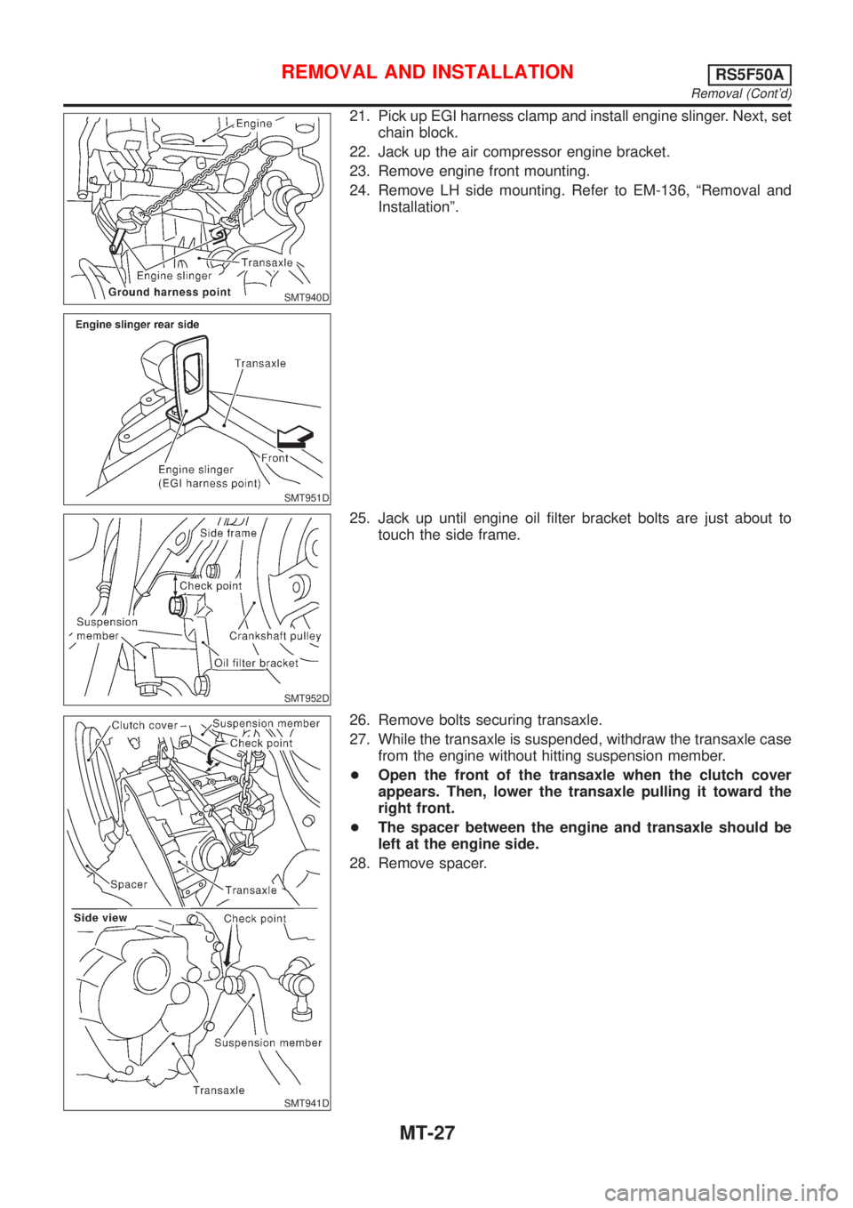
21. Pick up EGI harness clamp and install engine slinger. Next, set
chain block.
22. Jack up the air compressor engine bracket.
23. Remove engine front mounting.
24. Remove LH side mounting. Refer to EM-136, ªRemoval and
Installationº.
SMT952D
25. Jack up until engine oil filter bracket bolts are just about to
touch the side frame.
SMT941D
26. Remove bolts securing transaxle.
27. While the transaxle is suspended, withdraw the transaxle case
from the engine without hitting suspension member.
+Open the front of the transaxle when the clutch cover
appears. Then, lower the transaxle pulling it toward the
right front.
+The spacer between the engine and transaxle should be
left at the engine side.
28. Remove spacer.
REMOVAL AND INSTALLATIONRS5F50A
Removal (Cont'd)
MT-27
Page 1168 of 2493
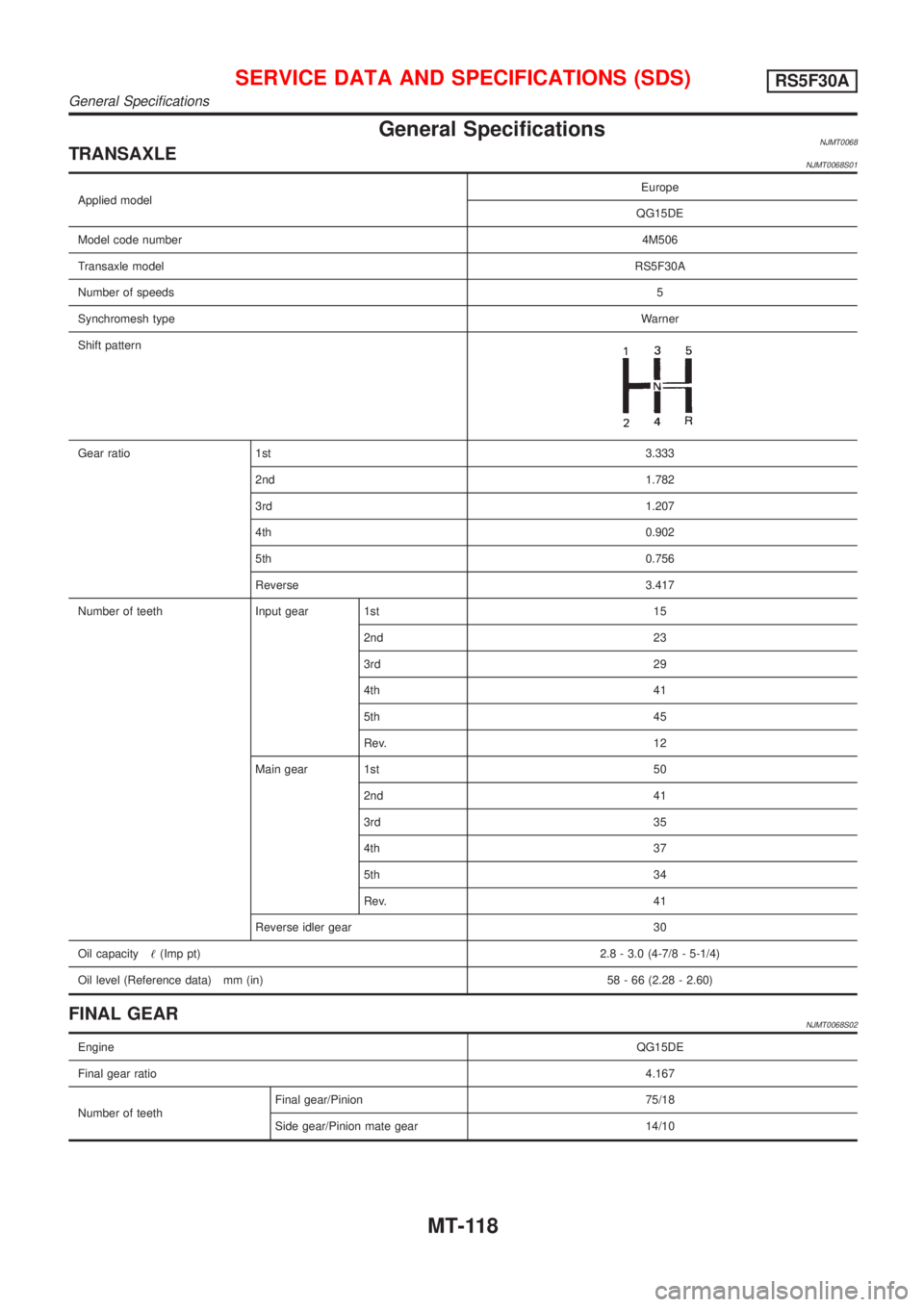
General SpecificationsNJMT0068TRANSAXLENJMT0068S01
Applied modelEurope
QG15DE
Model code number4M506
Transaxle modelRS5F30A
Number of speeds5
Synchromesh typeWarner
Shift pattern
Gear ratio 1st3.333
2nd 1.782
3rd1.207
4th0.902
5th0.756
Reverse 3.417
Number of teeth Input gear 1st 15
2nd 23
3rd 29
4th 41
5th 45
Rev. 12
Main gear 1st 50
2nd 41
3rd 35
4th 37
5th 34
Rev. 41
Reverse idler gear 30
Oil capacity!(Imp pt)2.8 - 3.0 (4-7/8 - 5-1/4)
Oil level (Reference data) mm (in) 58 - 66 (2.28 - 2.60)
FINAL GEARNJMT0068S02
EngineQG15DE
Final gear ratio4.167
Number of teethFinal gear/Pinion 75/18
Side gear/Pinion mate gear 14/10
SERVICE DATA AND SPECIFICATIONS (SDS)RS5F30A
General Specifications
MT-118
Page 1173 of 2493
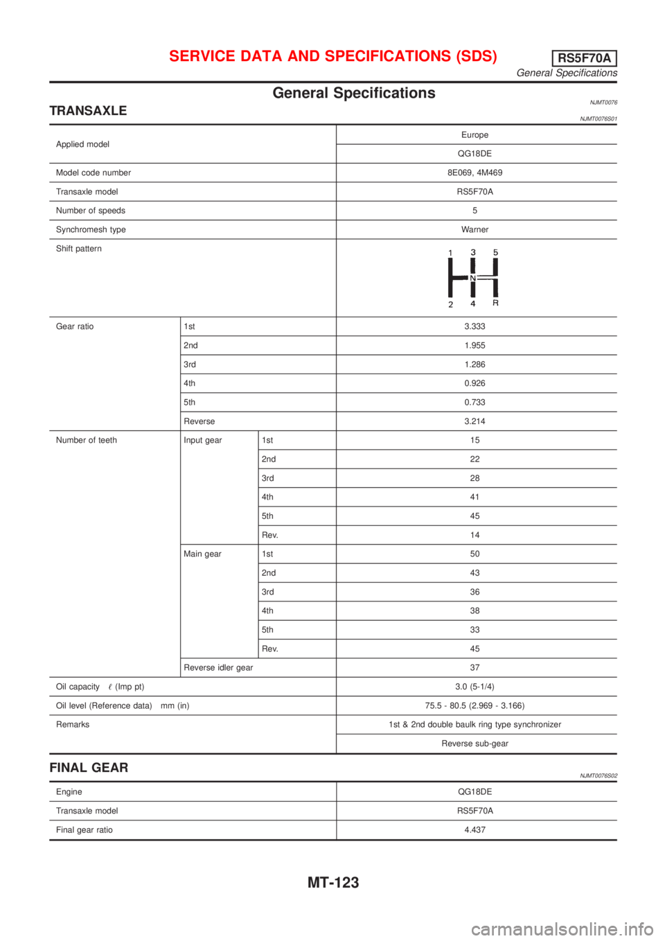
General SpecificationsNJMT0076TRANSAXLENJMT0076S01
Applied modelEurope
QG18DE
Model code number8E069, 4M469
Transaxle modelRS5F70A
Number of speeds5
Synchromesh typeWarner
Shift pattern
Gear ratio 1st3.333
2nd 1.955
3rd1.286
4th0.926
5th0.733
Reverse 3.214
Number of teeth Input gear 1st 15
2nd 22
3rd 28
4th 41
5th 45
Rev. 14
Main gear 1st 50
2nd 43
3rd 36
4th 38
5th 33
Rev. 45
Reverse idler gear 37
Oil capacity!(Imp pt)3.0 (5-1/4)
Oil level (Reference data) mm (in) 75.5 - 80.5 (2.969 - 3.166)
Remarks1st & 2nd double baulk ring type synchronizer
Reverse sub-gear
FINAL GEARNJMT0076S02
EngineQG18DE
Transaxle modelRS5F70A
Final gear ratio4.437
SERVICE DATA AND SPECIFICATIONS (SDS)RS5F70A
General Specifications
MT-123
Page 1181 of 2493
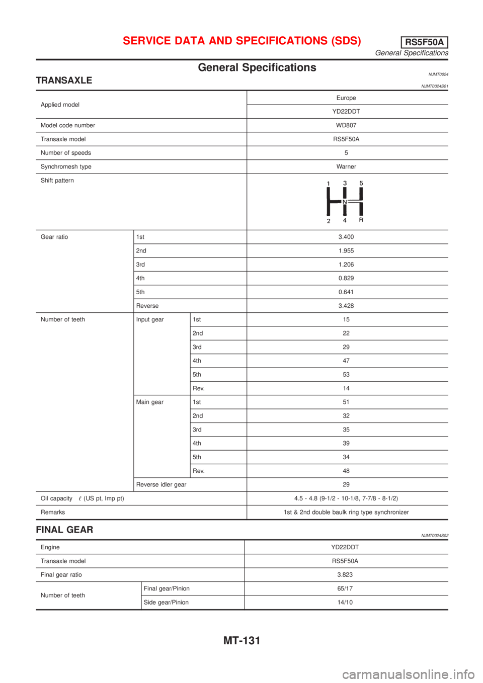
General SpecificationsNJMT0024TRANSAXLENJMT0024S01
Applied modelEurope
YD22DDT
Model code numberWD807
Transaxle modelRS5F50A
Number of speeds5
Synchromesh typeWarner
Shift pattern
Gear ratio 1st3.400
2nd 1.955
3rd 1.206
4th 0.829
5th 0.641
Reverse 3.428
Number of teeth Input gear 1st 15
2nd 22
3rd 29
4th 47
5th 53
Rev. 14
Main gear 1st 51
2nd 32
3rd 35
4th 39
5th 34
Rev. 48
Reverse idler gear 29
Oil capacity!(US pt, Imp pt) 4.5 - 4.8 (9-1/2 - 10-1/8, 7-7/8 - 8-1/2)
Remarks1st & 2nd double baulk ring type synchronizer
FINAL GEARNJMT0024S02
EngineYD22DDT
Transaxle modelRS5F50A
Final gear ratio3.823
Number of teethFinal gear/Pinion 65/17
Side gear/Pinion 14/10
SERVICE DATA AND SPECIFICATIONS (SDS)RS5F50A
General Specifications
MT-131
Page 1189 of 2493
Diagnostic Procedure ..............................................253
Component Inspection .............................................255
DTC P1705 THROTTLE POSITION SENSOR...........256
Description ...............................................................256
Wiring Diagram - AT - TPS ......................................259
Diagnostic Procedure ..............................................260
Component Inspection .............................................264
DTC P1760 OVERRUN CLUTCH SOLENOID
VALVE..........................................................................265
Description ...............................................................265
Wiring Diagram - AT - OVRCSV..............................267
Diagnostic Procedure ..............................................268
Component Inspection .............................................270
DTC BATT/FLUID TEMP SEN (A/T FLUID TEMP
SENSOR CIRCUIT AND TCM POWER SOURCE)....271
Description ...............................................................271
Wiring Diagram - AT - BA/FTS ................................273
Diagnostic Procedure ..............................................274
Component Inspection .............................................277
DTC VHCL SPEED SEN.MTR VEHICLE SPEED......278
Description ...............................................................278
Wiring Diagram - AT - VSSMTR ..............................280
Diagnostic Procedure ..............................................281
DTC CONTROL UNIT (RAM), CONTROL UNIT
(ROM)...........................................................................282
Description ...............................................................282
Diagnostic Procedure ..............................................282
DTC CONTROL UNIT (EEP ROM).............................284
Description ...............................................................284
Diagnostic Procedure ..............................................285
TROUBLE DIAGNOSES FOR SYMPTOMS...............286
Wiring Diagram - AT - NONDTC .............................286
1. O/D OFF Indicator Lamp Does Not Come On....288
2. Engine Cannot Be Started In²P²and²N²
Position ....................................................................291
3. In²P²Position, Vehicle Moves Forward Or
Backward When Pushed .........................................292
4. In²N²Position, Vehicle Moves ...........................293
5. Large Shock.²N²->²R²Position .......................295
6. Vehicle Does Not Creep Backward In²R²
Position ....................................................................297
7. Vehicle Does Not Creep Forward In²D²,²2²
Or²1²Position .........................................................300
8. Vehicle Cannot Be Started From D
1...................303
9. A/T Does Not Shift: D
1-> D2Or Does Not
Kickdown: D
4-> D2..................................................306
10. A/T Does Not Shift: D
2-> D3.............................309
11. A/T Does Not Shift: D
3-> D4.............................312
12. A/T Does Not Perform Lock-up .........................315
13. A/T Does Not Hold Lock-up Condition ..............31714. Lock-up Is Not Released ...................................319
15. Engine Speed Does Not Return To Idle (Light
Braking D
4-> D3).....................................................320
16. Vehicle Does Not Start From D
1.......................322
17. A/T Does Not Shift: D
4-> D3, When
Overdrive Control Switch²ON²->²OFF²...............323
18. A/T Does Not Shift: D
3-> 22, When Selector
Lever²D²->²2²Position.........................................324
19. A/T Does Not Shift: 2
2-> 11, When Selector
Lever²2²->²1²Position .........................................325
20. Vehicle Does Not Decelerate By Engine
Brake........................................................................326
21. TCM Self-diagnosis Does Not Activate (PNP,
Overdrive Control and Throttle Position Switches
Circuit Checks) ........................................................326
A/T SHIFT LOCK SYSTEM.........................................335
Description ...............................................................335
Shift Lock System Electrical Parts Location............335
Wiring Diagram - SHIFT -........................................336
Diagnostic Procedure ..............................................337
KEY INTERLOCK CABLE..........................................341
Components.............................................................341
Removal ...................................................................341
Installation ................................................................342
ON-VEHICLE SERVICE..............................................343
Control Valve Assembly and Accumulators .............343
Control Cable Adjustment ........................................344
Park/Neutral Position (PNP) Switch Adjustment .....344
Differential Side Oil Seal Replacement ...................345
Revolution Sensor Replacement .............................345
REMOVAL AND INSTALLATION...............................346
Removal ...................................................................346
Installation ................................................................347
OVERHAUL.................................................................349
Components-1 .........................................................349
Components-2 .........................................................350
Components-3 .........................................................351
Oil Channel ..............................................................352
Locations of Adjusting Shims, Needle Bearings,
Thrust Washers and Snap Rings ............................353
DISASSEMBLY............................................................354
REPAIR FOR COMPONENT PARTS.........................368
Manual Shaft............................................................368
Oil Pump ..................................................................371
Control Valve Assembly ...........................................375
Control Valve Upper Body .......................................384
Control Valve Lower Body .......................................388
Reverse Clutch ........................................................390
High Clutch ..............................................................394
Forward Clutch and Overrun Clutch........................399
Low & Reverse Brake..............................................406
CONTENTS(Cont'd)
AT-3