2001 NISSAN ALMERA N16 engine oil
[x] Cancel search: engine oilPage 840 of 2493

SYSTEM Ð ENGINE CONTROL system
Malfunction
SYMPTOM
Reference page
Feature of symptom, Check pointROUGH IDLE/HUNTING
IDLING VIBRATION
SLOW/NO RETURN TO IDLE
OVERHEAT/HIGH ENGINE COOLANT TEMPERATURE
EXCESSIVE FUEL CONSUMPTION
EXCESSIVE OIL CONSUMPTION
ABNORMAL SMOKE COLOR
DEAD BATTERY (UNDER CHARGE)
Malfunction indicator illuminates.
Can be detected by CONSULT-II?BLACK SMOKE
WHITE SMOKEWarranty symptom code AG AH AJ AK AL AM AP HA
ENGINE CONTROL
Electronic control fuel injection pump
circuit*a, *b 1 1 1
11 Ð
*c, *d 1
Mass air flow sensor circuit*a, *c
1 EC-566
*b 1
Engine coolant temperature sensor cir-
cuit*a, *b 1 1 1 1 1 EC-572 *1
Vehicle speed sensor circuit *a, *b 1 EC-593
1 - 5: The numbers refer to the order of inspection.
(continued on next page)
*a: Open
*b: Short
*c: Ground short
*d: Noise
*1: Compensation according to engine coolant temperature does not function.
TROUBLE DIAGNOSIS Ð GENERAL DESCRIPTIONYD
Symptom Matrix Chart (Cont'd)
EC-544
Page 842 of 2493

SYSTEM Ð ENGINE CONTROL system
Malfunction
SYMPTOM
Reference page
Feature of symptom, Check pointROUGH IDLE/HUNTING
IDLING VIBRATION
SLOW/NO RETURN TO IDLE
OVERHEAT/HIGH ENGINE COOLANT TEMPERATURE
EXCESSIVE FUEL CONSUMPTION
EXCESSIVE OIL CONSUMPTION
ABNORMAL SMOKE COLOR
DEAD BATTERY (UNDER CHARGE)
Malfunction indicator illuminates.
Can be detected by CONSULT-II?BLACK SMOKE
WHITE SMOKEWarranty symptom code AG AH AJ AK AL AM AP HA
ENGINE CONTROL
Fuel cut system line*a, *c 1 1
EC-612
*b*2
Accelerator position sensor circuit *a, *b 1 1 EC-577
Crankshaft position sensor (TDC) circuit*a, *b
1 1 1 1 EC-587
*d
1 - 5: The numbers refer to the order of inspection.
(continued on next page)
*a: Open
*b: Short
*c: Ground short
*d: Noise
*2: Engine runs on after turning ignition switch OFF.
TROUBLE DIAGNOSIS Ð GENERAL DESCRIPTIONYD
Symptom Matrix Chart (Cont'd)
EC-546
Page 844 of 2493

SYSTEM Ð ENGINE CONTROL system
Malfunction
SYMPTOM
Reference page
Feature of symptom, Check pointROUGH IDLE/HUNTING
IDLING VIBRATION
SLOW/NO RETURN TO IDLE
OVERHEAT/HIGH ENGINE COOLANT TEMPERATURE
EXCESSIVE FUEL CONSUMPTION
EXCESSIVE OIL CONSUMPTION
ABNORMAL SMOKE COLOR
DEAD BATTERY (UNDER CHARGE)
Malfunction indicator illuminates.
Can be detected by CONSULT-II?BLACK SMOKE
WHITE SMOKEWarranty symptom code AG AH AJ AK AL AM AP HA
ENGINE CONTROL
Start signal circuit *a, *b EC-693 *3
Accelerator position switch (Idle) circuit*a, *c
EC-577
*b 1 1 *4
Ignition switch circuit*a
EC-560
*b*5
Power supply for ECM circuit*a
1 1 EC-560
*b
1 - 5: The numbers refer to the order of inspection.
(continued on next page)
*a: Open
*b: Short
*c: Ground short
*d: Noise
*3: Start control does not function.
*4: Accelerator position sensor NG signal is output.
*5: Engine does not stop.
TROUBLE DIAGNOSIS Ð GENERAL DESCRIPTIONYD
Symptom Matrix Chart (Cont'd)
EC-548
Page 846 of 2493

SYSTEM Ð ENGINE CONTROL system
Malfunction
SYMPTOM
Reference page
Feature of symptom, Check pointROUGH IDLE/HUNTING
IDLING VIBRATION
SLOW/NO RETURN TO IDLE
OVERHEAT/HIGH ENGINE COOLANT TEMPERATURE
EXCESSIVE FUEL CONSUMPTION
EXCESSIVE OIL CONSUMPTION
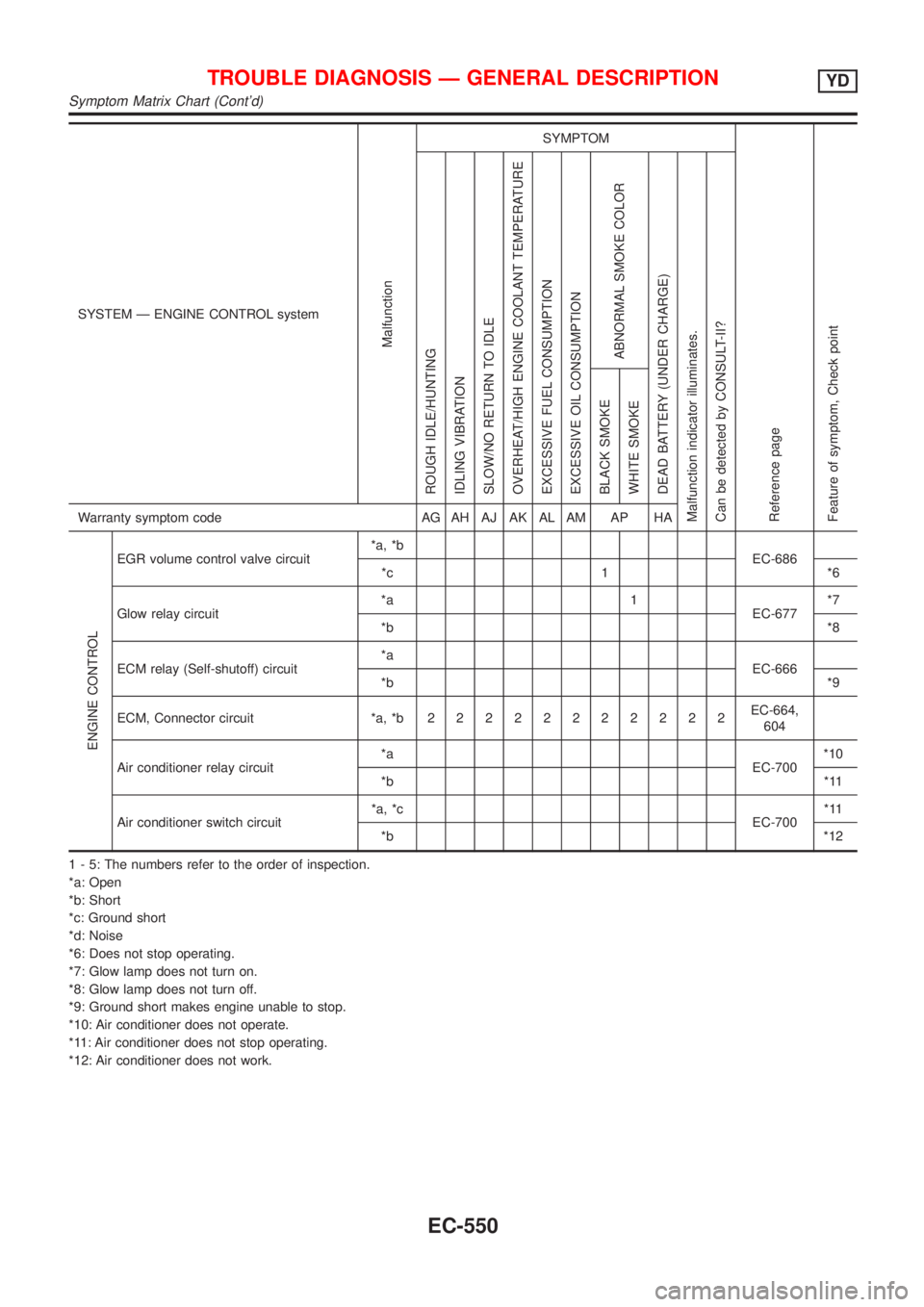
ABNORMAL SMOKE COLOR
DEAD BATTERY (UNDER CHARGE)
Malfunction indicator illuminates.
Can be detected by CONSULT-II?BLACK SMOKE
WHITE SMOKEWarranty symptom code AG AH AJ AK AL AM AP HA
ENGINE CONTROL
EGR volume control valve circuit*a, *b
EC-686
*c 1 *6
Glow relay circuit*a 1
EC-677*7
*b*8
ECM relay (Self-shutoff) circuit*a
EC-666
*b*9
ECM, Connector circuit *a, *b22222222222EC-664,
604
Air conditioner relay circuit*a
EC-700*10
*b*11
Air conditioner switch circuit*a, *c
EC-700*11
*b*12
1 - 5: The numbers refer to the order of inspection.
*a: Open
*b: Short
*c: Ground short
*d: Noise
*6: Does not stop operating.
*7: Glow lamp does not turn on.
*8: Glow lamp does not turn off.
*9: Ground short makes engine unable to stop.
*10: Air conditioner does not operate.
*11: Air conditioner does not stop operating.
*12: Air conditioner does not work.
TROUBLE DIAGNOSIS Ð GENERAL DESCRIPTIONYD
Symptom Matrix Chart (Cont'd)
EC-550
Page 915 of 2493
![NISSAN ALMERA N16 2001 Electronic Repair Manual TERMI-
NAL
NO.WIRE
COLORITEM CONDITION DATA(DC Voltage)
221 LG/B Cooling fan relay (High)[Engine is running]
+Cooling fans are not operating
+Cooling fans are operating at low speedBATTERY VOLTAGE
(11 NISSAN ALMERA N16 2001 Electronic Repair Manual TERMI-
NAL
NO.WIRE
COLORITEM CONDITION DATA(DC Voltage)
221 LG/B Cooling fan relay (High)[Engine is running]
+Cooling fans are not operating
+Cooling fans are operating at low speedBATTERY VOLTAGE
(11](/manual-img/5/57351/w960_57351-914.png)
TERMI-
NAL
NO.WIRE
COLORITEM CONDITION DATA(DC Voltage)
221 LG/B Cooling fan relay (High)[Engine is running]
+Cooling fans are not operating
+Cooling fans are operating at low speedBATTERY VOLTAGE
(11 - 14V)
[Engine is running]
+Cooling fans are operating at high speedApproximately 0.1V
On Board Diagnosis LogicNJEC0663This diagnosis continuously monitors the engine coolant temperature.
If the cooling fan or another component in the cooling system malfunctions, engine coolant temperature will
rise.
When the engine coolant temperature reaches an abnormally high temperature condition, a malfunction is
indicated.
DTC Malfunction is detected when ... Check Items (Possible Cause)
P1217
0208+Cooling fan does not operate properly (Overheat).
+Cooling fan system does not operate properly
(Overheat).
+Engine coolant was not added to the system using
the proper filling method.+Harness or connectors
(The cooling fan circuit is open or shorted.)
+Cooling fan
+Radiator hose
+Radiator
+Radiator cap
+Water pump
+Thermostat
+Engine coolant temperature sensor
For more information, refer to ªMAIN 12 CAUSES OF
OVERHEATINGº, EC-633.
CAUTION:
When a malfunction is indicated, be sure to replace the coolant following the procedure in the LC-43,
ªChanging Engine Coolantº. Also, replace the engine oil.
1) Fill radiator with coolant up to specified level with a filling speed of 2 liters per minute. Be sure
to use coolant with the proper mixture ratio. Refer to MA-22, ªEngine Coolant Mixture Ratioº.
2) After refilling coolant, run engine to ensure that no water-flow noise is emitted.
DTC P1217 OVER HEATYD
ECM Terminals and Reference Value (Cont'd)
EC-619
Page 1030 of 2493

NJCL0004
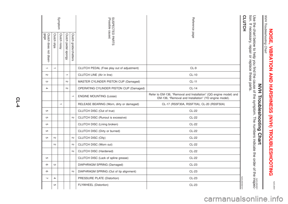
NVH Troubleshooting ChartNJCL0004S01Use the chart below to help you find the cause of the symptom. The numbers indicate the order of the inspec-
tion. If necessary, repair or replace these parts.
CLUTCHNJCL0004S0101
Reference pageCL-9
CL-10
CL-11
CL-14
Refer to EM-136, ªRemoval and Installationº (QG engine model) and
EM-136, ªRemoval and Installationº (YD engine model).
CL-17 (RS5F30A, RS5F70A), CL-20 (RS5F50A)
CL-22
CL-22
CL-22
CL-22
CL-22
CL-22
CL-22
CL-22
CL-23
CL-23
CL-23
CL-23
SUSPECTED PARTS
(Possible cause)
CLUTCH PEDAL (Free play out of adjustment)
CLUTCH LINE (Air in line)
MASTER CYLINDER PISTON CUP (Damaged)
OPERATING CYLINDER PISTON CUP (Damaged)
ENGINE MOUNTING (Loose)
RELEASE BEARING (Worn, dirty or damaged)
CLUTCH DISC (Out of true)
CLUTCH DISC (Runout is excessive)
CLUTCH DISC (Lining broken)
CLUTCH DISC (Dirty or burned)
CLUTCH DISC (Oily)
CLUTCH DISC (Worn out)
CLUTCH DISC (Hardened)
CLUTCH DISC (Lack of spline grease)
DIAPHRAGM SPRING (Damaged)
DIAPHRAGM SPRING (Out of tip alignment)
PRESSURE PLATE (Distortion)
FLYWHEEL (Distortion)
SymptomClutch grabs/chatters 1 2 2 2 2 2
Clutch pedal spongy 1 2 2
Clutch noisy 1
Clutch slips 1 2 2 3 4 5
Clutch does not disen-
gage1234 55555 5667
NOISE, VIBRATION AND HARSHNESS (NVH) TROUBLESHOOTING
NVH Troubleshooting Chart
CL-4
Page 1051 of 2493

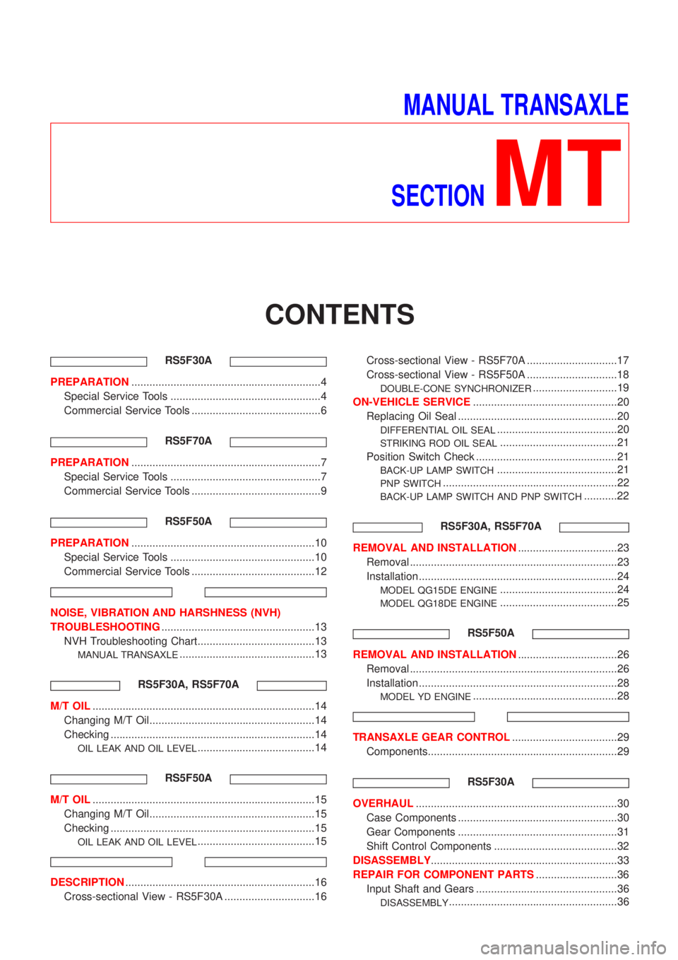
MANUAL TRANSAXLE
SECTION
MT
CONTENTS
RS5F30A
PREPARATION...............................................................4
Special Service Tools ..................................................4
Commercial Service Tools ...........................................6
RS5F70A
PREPARATION...............................................................7
Special Service Tools ..................................................7
Commercial Service Tools ...........................................9
RS5F50A
PREPARATION.............................................................10
Special Service Tools ................................................10
Commercial Service Tools .........................................12
NOISE, VIBRATION AND HARSHNESS (NVH)
TROUBLESHOOTING...................................................13
NVH Troubleshooting Chart.......................................13
MANUAL TRANSAXLE.............................................13
RS5F30A, RS5F70A
M/T OIL..........................................................................14
Changing M/T Oil.......................................................14
Checking ....................................................................14
OIL LEAK AND OIL LEVEL.......................................14
RS5F50A
M/T OIL..........................................................................15
Changing M/T Oil.......................................................15
Checking ....................................................................15
OIL LEAK AND OIL LEVEL.......................................15
DESCRIPTION...............................................................16
Cross-sectional View - RS5F30A ..............................16Cross-sectional View - RS5F70A ..............................17
Cross-sectional View - RS5F50A ..............................18
DOUBLE-CONE SYNCHRONIZER............................19
ON-VEHICLE SERVICE................................................20
Replacing Oil Seal .....................................................20
DIFFERENTIAL OIL SEAL........................................20
STRIKING ROD OIL SEAL.......................................21
Position Switch Check ...............................................21
BACK-UP LAMP SWITCH........................................21
PNP SWITCH..........................................................22
BACK-UP LAMP SWITCH AND PNP SWITCH...........22
RS5F30A, RS5F70A
REMOVAL AND INSTALLATION.................................23
Removal .....................................................................23
Installation ..................................................................24
MODEL QG15DE ENGINE.......................................24
MODEL QG18DE ENGINE.......................................25
RS5F50A
REMOVAL AND INSTALLATION.................................26
Removal .....................................................................26
Installation ..................................................................28
MODEL YD ENGINE................................................28
TRANSAXLE GEAR CONTROL...................................29
Components...............................................................29
RS5F30A
OVERHAUL...................................................................30
Case Components .....................................................30
Gear Components .....................................................31
Shift Control Components .........................................32
DISASSEMBLY..............................................................33
REPAIR FOR COMPONENT PARTS...........................36
Input Shaft and Gears ...............................................36
DISASSEMBLY........................................................36
Page 1064 of 2493

SMA145AA
SMT512C
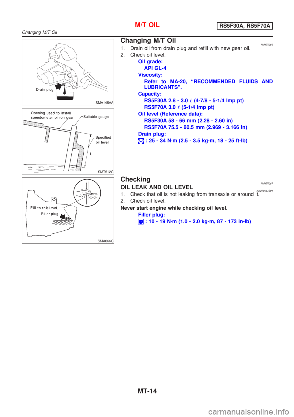
Changing M/T OilNJMT00861. Drain oil from drain plug and refill with new gear oil.
2. Check oil level.
Oil grade:
API GL-4
Viscosity:
Refer to MA-20, ªRECOMMENDED FLUIDS AND
LUBRICANTSº.
Capacity:
RS5F30A 2.8 - 3.0!(4-7/8 - 5-1/4 Imp pt)
RS5F70A 3.0!(5-1/4 Imp pt)
Oil level (Reference data):
RS5F30A 58 - 66 mm (2.28 - 2.60 in)
RS5F70A 75.5 - 80.5 mm (2.969 - 3.166 in)
Drain plug:
: 25 - 34 N´m (2.5 - 3.5 kg-m, 18 - 25 ft-lb)
SMA066C
CheckingNJMT0087OIL LEAK AND OIL LEVELNJMT0087S011. Check that oil is not leaking from transaxle or around it.
2. Check oil level.
Never start engine while checking oil level.
Filler plug:
: 10 - 19 N´m (1.0 - 2.0 kg-m, 87 - 173 in-lb)
M/T OILRS5F30A, RS5F70A
Changing M/T Oil
MT-14