Page 1206 of 2493
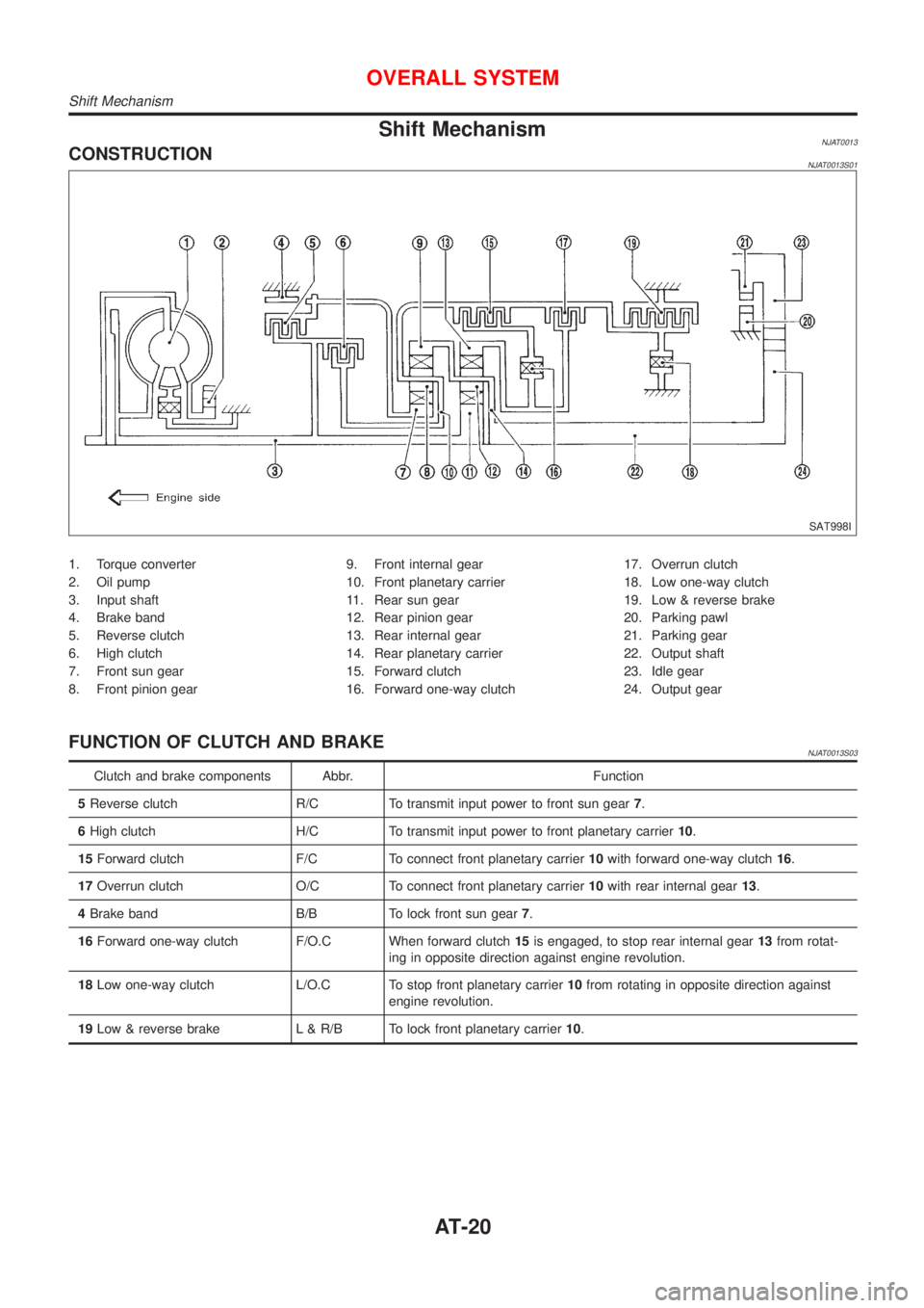
Shift MechanismNJAT0013CONSTRUCTIONNJAT0013S01
SAT998I
1. Torque converter
2. Oil pump
3. Input shaft
4. Brake band
5. Reverse clutch
6. High clutch
7. Front sun gear
8. Front pinion gear9. Front internal gear
10. Front planetary carrier
11. Rear sun gear
12. Rear pinion gear
13. Rear internal gear
14. Rear planetary carrier
15. Forward clutch
16. Forward one-way clutch17. Overrun clutch
18. Low one-way clutch
19. Low & reverse brake
20. Parking pawl
21. Parking gear
22. Output shaft
23. Idle gear
24. Output gear
FUNCTION OF CLUTCH AND BRAKENJAT0013S03
Clutch and brake components Abbr. Function
5Reverse clutch R/C To transmit input power to front sun gear7.
6High clutch H/C To transmit input power to front planetary carrier10.
15Forward clutch F/C To connect front planetary carrier10with forward one-way clutch16.
17Overrun clutch O/C To connect front planetary carrier10with rear internal gear13.
4Brake band B/B To lock front sun gear7.
16Forward one-way clutch F/O.C When forward clutch15is engaged, to stop rear internal gear13from rotat-
ing in opposite direction against engine revolution.
18Low one-way clutch L/O.C To stop front planetary carrier10from rotating in opposite direction against
engine revolution.
19Low & reverse brake L & R/B To lock front planetary carrier10.
OVERALL SYSTEM
Shift Mechanism
AT-20
Page 1207 of 2493
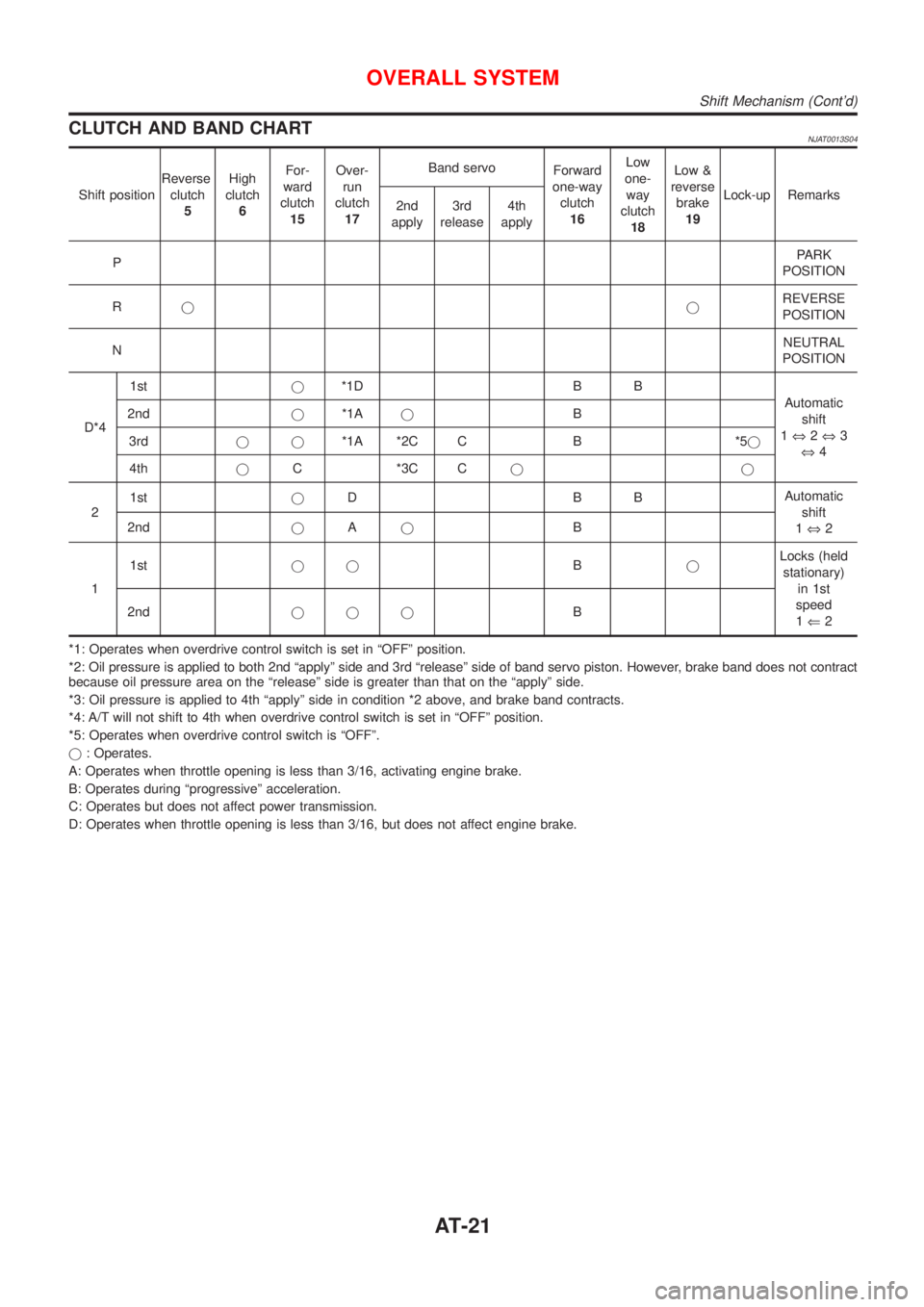
CLUTCH AND BAND CHARTNJAT0013S04
Shift positionReverse
clutch
5High
clutch
6For-
ward
clutch
15Over-
run
clutch
17Band servo
Forward
one-way
clutch
16Low
one-
way
clutch
18Low &
reverse
brake
19Lock-up Remarks
2nd
apply3rd
release4th
apply
PPARK
POSITION
RjjREVERSE
POSITION
NNEUTRAL
POSITION
D*41stj*1D B B
Automatic
shift
1Û2Û3
Û4 2ndj*1AjB
3rdjj*1A *2C C B *5j
4thjC *3C Cjj
21stjDBBAutomatic
shift
1Û2 2ndjAjB
11stjjBjLocks (held
stationary)
in 1st
speed
1Ü2 2ndjjjB
*1: Operates when overdrive control switch is set in ªOFFº position.
*2: Oil pressure is applied to both 2nd ªapplyº side and 3rd ªreleaseº side of band servo piston. However, brake band does not contract
because oil pressure area on the ªreleaseº side is greater than that on the ªapplyº side.
*3: Oil pressure is applied to 4th ªapplyº side in condition *2 above, and brake band contracts.
*4: A/T will not shift to 4th when overdrive control switch is set in ªOFFº position.
*5: Operates when overdrive control switch is ªOFFº.
j: Operates.
A: Operates when throttle opening is less than 3/16, activating engine brake.
B: Operates during ªprogressiveº acceleration.
C: Operates but does not affect power transmission.
D: Operates when throttle opening is less than 3/16, but does not affect engine brake.
OVERALL SYSTEM
Shift Mechanism (Cont'd)
AT-21
Page 1221 of 2493
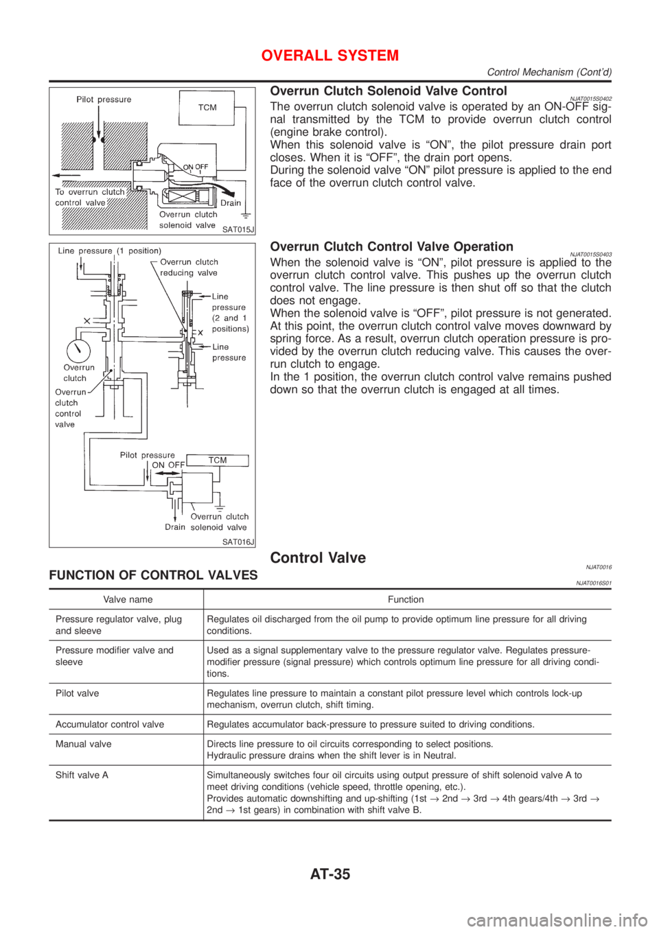
SAT015J
Overrun Clutch Solenoid Valve ControlNJAT0015S0402The overrun clutch solenoid valve is operated by an ON-OFF sig-
nal transmitted by the TCM to provide overrun clutch control
(engine brake control).
When this solenoid valve is ªONº, the pilot pressure drain port
closes. When it is ªOFFº, the drain port opens.
During the solenoid valve ªONº pilot pressure is applied to the end
face of the overrun clutch control valve.
SAT016J
Overrun Clutch Control Valve OperationNJAT0015S0403When the solenoid valve is ªONº, pilot pressure is applied to the
overrun clutch control valve. This pushes up the overrun clutch
control valve. The line pressure is then shut off so that the clutch
does not engage.
When the solenoid valve is ªOFFº, pilot pressure is not generated.
At this point, the overrun clutch control valve moves downward by
spring force. As a result, overrun clutch operation pressure is pro-
vided by the overrun clutch reducing valve. This causes the over-
run clutch to engage.
In the 1 position, the overrun clutch control valve remains pushed
down so that the overrun clutch is engaged at all times.
Control ValveNJAT0016FUNCTION OF CONTROL VALVESNJAT0016S01
Valve name Function
Pressure regulator valve, plug
and sleeveRegulates oil discharged from the oil pump to provide optimum line pressure for all driving
conditions.
Pressure modifier valve and
sleeveUsed as a signal supplementary valve to the pressure regulator valve. Regulates pressure-
modifier pressure (signal pressure) which controls optimum line pressure for all driving condi-
tions.
Pilot valve Regulates line pressure to maintain a constant pilot pressure level which controls lock-up
mechanism, overrun clutch, shift timing.
Accumulator control valve Regulates accumulator back-pressure to pressure suited to driving conditions.
Manual valve Directs line pressure to oil circuits corresponding to select positions.
Hydraulic pressure drains when the shift lever is in Neutral.
Shift valve A Simultaneously switches four oil circuits using output pressure of shift solenoid valve A to
meet driving conditions (vehicle speed, throttle opening, etc.).
Provides automatic downshifting and up-shifting (1st®2nd®3rd®4th gears/4th®3rd®
2nd®1st gears) in combination with shift valve B.
OVERALL SYSTEM
Control Mechanism (Cont'd)
AT-35
Page 1222 of 2493
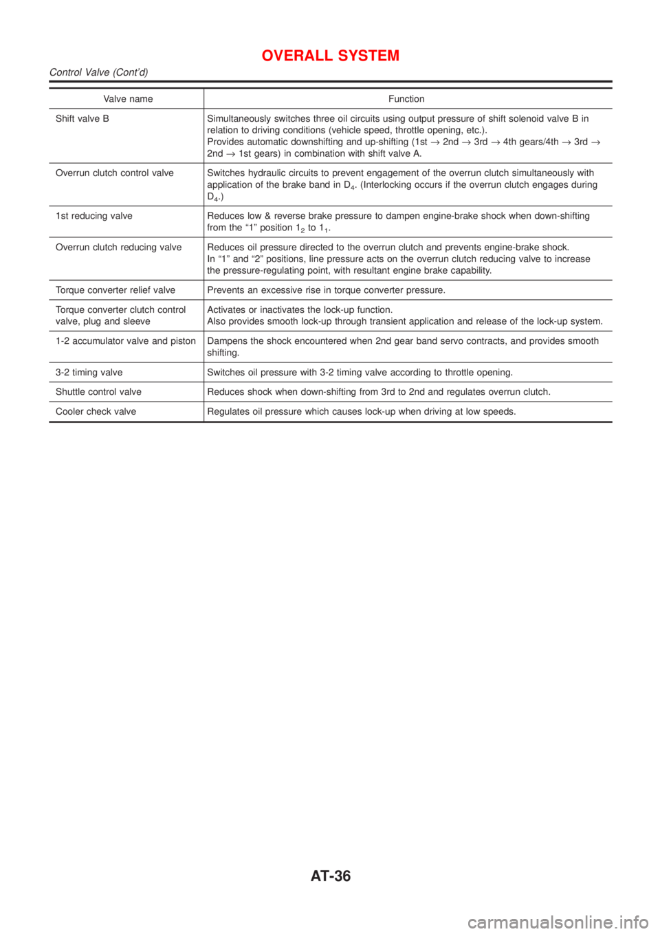
Valve name Function
Shift valve B Simultaneously switches three oil circuits using output pressure of shift solenoid valve B in
relation to driving conditions (vehicle speed, throttle opening, etc.).
Provides automatic downshifting and up-shifting (1st®2nd®3rd®4th gears/4th®3rd®
2nd®1st gears) in combination with shift valve A.
Overrun clutch control valve Switches hydraulic circuits to prevent engagement of the overrun clutch simultaneously with
application of the brake band in D
4. (Interlocking occurs if the overrun clutch engages during
D
4.)
1st reducing valve Reduces low & reverse brake pressure to dampen engine-brake shock when down-shifting
from the ª1º position 1
2to 11.
Overrun clutch reducing valve Reduces oil pressure directed to the overrun clutch and prevents engine-brake shock.
In ª1º and ª2º positions, line pressure acts on the overrun clutch reducing valve to increase
the pressure-regulating point, with resultant engine brake capability.
Torque converter relief valve Prevents an excessive rise in torque converter pressure.
Torque converter clutch control
valve, plug and sleeveActivates or inactivates the lock-up function.
Also provides smooth lock-up through transient application and release of the lock-up system.
1-2 accumulator valve and piston Dampens the shock encountered when 2nd gear band servo contracts, and provides smooth
shifting.
3-2 timing valve Switches oil pressure with 3-2 timing valve according to throttle opening.
Shuttle control valve Reduces shock when down-shifting from 3rd to 2nd and regulates overrun clutch.
Cooler check valve Regulates oil pressure which causes lock-up when driving at low speeds.
OVERALL SYSTEM
Control Valve (Cont'd)
AT-36
Page 1264 of 2493
SAT767B
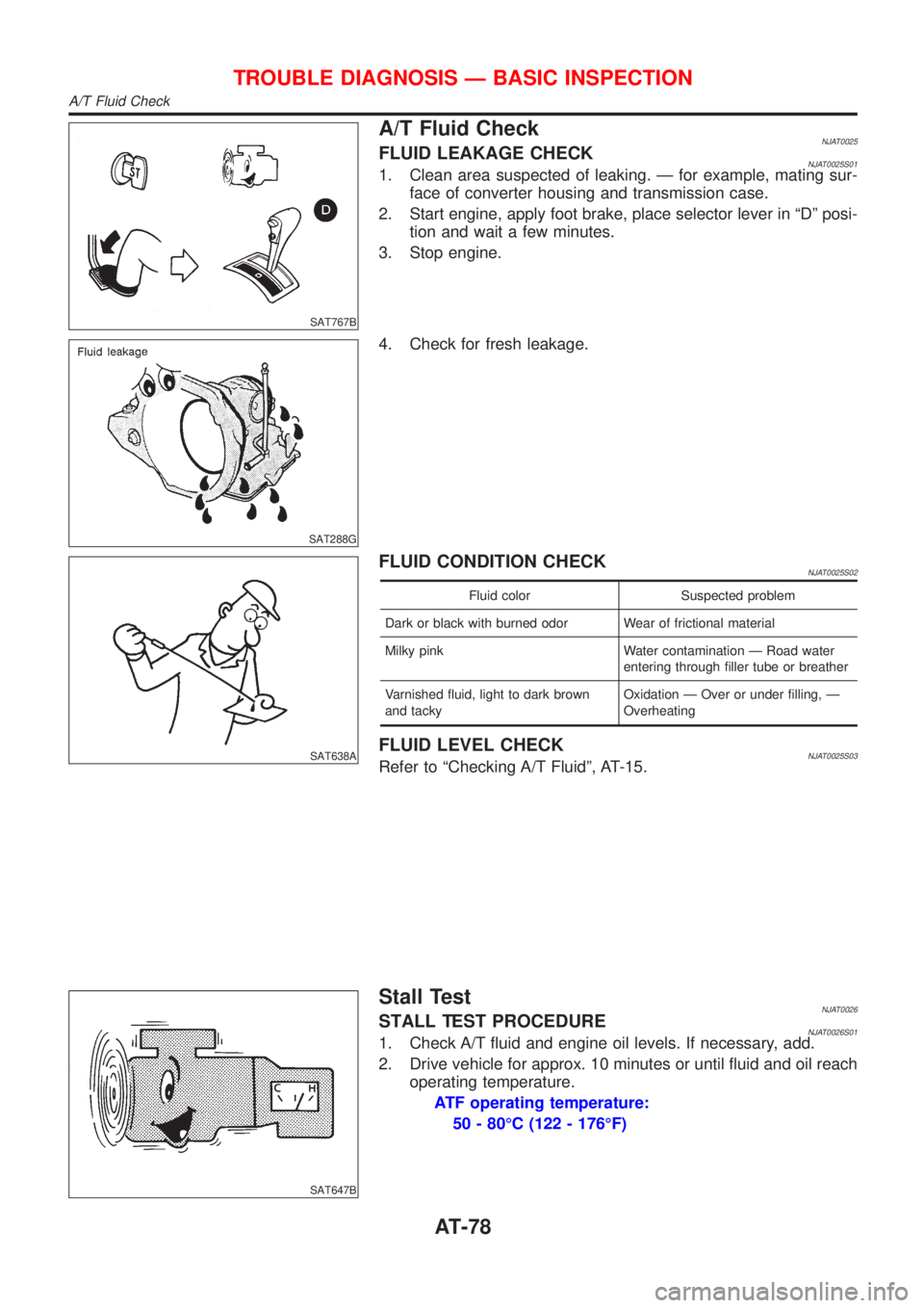
A/T Fluid CheckNJAT0025FLUID LEAKAGE CHECKNJAT0025S011. Clean area suspected of leaking. Ð for example, mating sur-
face of converter housing and transmission case.
2. Start engine, apply foot brake, place selector lever in ªDº posi-
tion and wait a few minutes.
3. Stop engine.
SAT288G
4. Check for fresh leakage.
SAT638A
FLUID CONDITION CHECKNJAT0025S02
Fluid color Suspected problem
Dark or black with burned odor Wear of frictional material
Milky pink Water contamination Ð Road water
entering through filler tube or breather
Varnished fluid, light to dark brown
and tackyOxidation Ð Over or under filling, Ð
Overheating
FLUID LEVEL CHECKNJAT0025S03Refer to ªChecking A/T Fluidº, AT-15.
SAT647B
Stall TestNJAT0026STALL TEST PROCEDURENJAT0026S011. Check A/T fluid and engine oil levels. If necessary, add.
2. Drive vehicle for approx. 10 minutes or until fluid and oil reach
operating temperature.
ATF operating temperature:
50 - 80ÉC (122 - 176ÉF)
TROUBLE DIAGNOSIS Ð BASIC INSPECTION
A/T Fluid Check
AT-78
Page 1268 of 2493
SAT561J
Line Pressure TestNJAT0027LINE PRESSURE TEST PORTSNJAT0027S01Location of line pressure test ports are shown in the illustration.
+Always replace pressure plugs as they are self-sealing
bolts.
SAT647B
LINE PRESSURE TEST PROCEDURENJAT0027S021. Check A/T fluid and engine oil levels. If necessary, add fluid or
oil.
2. Drive vehicle for approx. 10 minutes or until engine oil and ATF
reach operating temperature.
ATF operating temperature:
50 - 80ÉC (122 - 176ÉF)
UAT008
3. Install pressure gauge to corresponding line pressure port.
UAT008
4. Set parking brake and block wheels.
+Continue to depress brake pedal fully while line pressure
test is being performed at stall speed.
SAT493G
5. Start engine and measure line pressure at idle and stall speed.
+When measuring line pressure at stall speed, follow the
stall test procedure.
Line pressure: Refer to SDS, AT-450.
TROUBLE DIAGNOSIS Ð BASIC INSPECTION
Line Pressure Test
AT-82
Page 1269 of 2493
JUDGEMENT OF LINE PRESSURE TESTNJAT0027S03
Judgement Suspected parts
At idleLine pressure is low in all positions.+Oil pump wear
+Control piston damage
+Pressure regulator valve or plug sticking
+Spring for pressure regulator valve damaged
+Fluid pressure leakage between oil strainer and pressure regulator valve
+Clogged strainer
Line pressure is low in particular
position.+Fluid pressure leakage between manual valve and particular clutch
+For example, line pressure is:
þ Low in ªRº and ª1º positions, but
þ Normal in ªDº and ª2º positions.
Therefore, fluid leakage exists at or around low and reverse brake circuit.
Refer to ªCLUTCH AND BAND CHARTº, AT-21.
Line pressure is high.+Maladjustment of throttle position sensor
+A/T fluid temperature sensor damaged
+Line pressure solenoid valve sticking
+Short circuit of line pressure solenoid valve circuit
+Pressure modifier valve sticking
+Pressure regulator valve or plug sticking
+Open in dropping resistor circuit
At stall
speedLine pressure is low.+Maladjustment of throttle position sensor
+Line pressure solenoid valve sticking
+Short circuit of line pressure solenoid valve circuit
+Pressure regulator valve or plug sticking
+Pressure modifier valve sticking
+Pilot valve sticking
SAT786A
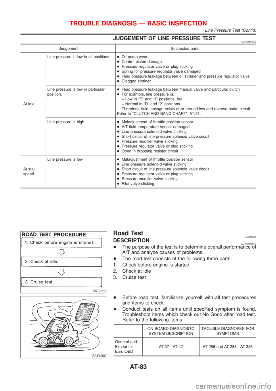
Road TestNJAT0028DESCRIPTIONNJAT0028S01+The purpose of the test is to determine overall performance of
A/T and analyze causes of problems.
+The road test consists of the following three parts:
1. Check before engine is started
2. Check at idle
3. Cruise test
SAT496G
+Before road test, familiarize yourself with all test procedures
and items to check.
+Conduct tests on all items until specified symptom is found.
Troubleshoot items which check out No Good after road test.
Refer to the following items.
ON BOARD DIAGNOSITC
SYSTEM DESCRIPTIONTROUBLE DIAGNOSES FOR
SYMPTOMS
General and
Except for
Euro-OBDAT-37 - AT-47 AT-286 and AT-288 - AT-326
TROUBLE DIAGNOSIS Ð BASIC INSPECTION
Line Pressure Test (Cont'd)
AT-83
Page 1279 of 2493
Cruise Test Ð Part 1=NJAT0028S0404
1 CHECK STARTING GEAR (D1) POSITION
1. Drive vehicle for approx. 10 minutes to warm engine oil and ATF up to operating temperature.
ATF operating temperature:
50 - 80ÉC (122 - 176ÉF)
2. Park vehicle on flat surface.
3. Set overdrive control switch to ªONº position.
4. Move selector lever to ªPº position.
SAT774B
5. Start engine.
6. Move selector lever to ªDº position.
SAT775B
7. Accelerate vehicle by constantly depressing accelerator pedal halfway.
SAT495G
8. Does vehicle start from D1?
Read gear position.
YesorNo
Ye s©GO TO 2.
No©Go to ª8. Vehicle Cannot Be Started From D
1º, AT-303. Continue ROAD TEST.
TROUBLE DIAGNOSIS Ð BASIC INSPECTION
Road Test (Cont'd)
AT-93