Page 1507 of 2493
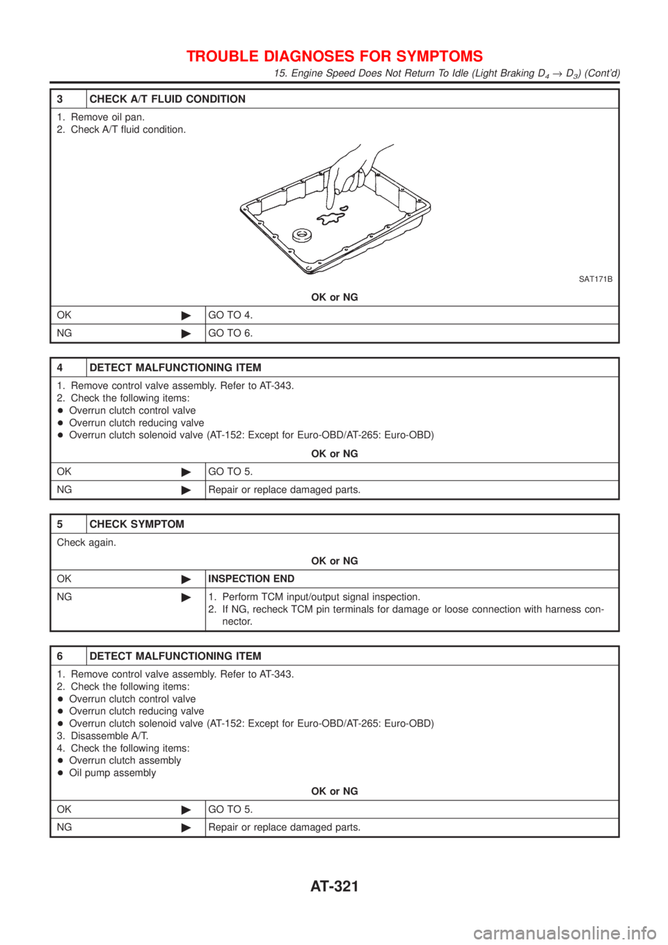
3 CHECK A/T FLUID CONDITION
1. Remove oil pan.
2. Check A/T fluid condition.
SAT171B
OK or NG
OK©GO TO 4.
NG©GO TO 6.
4 DETECT MALFUNCTIONING ITEM
1. Remove control valve assembly. Refer to AT-343.
2. Check the following items:
+Overrun clutch control valve
+Overrun clutch reducing valve
+Overrun clutch solenoid valve (AT-152: Except for Euro-OBD/AT-265: Euro-OBD)
OK or NG
OK©GO TO 5.
NG©Repair or replace damaged parts.
5 CHECK SYMPTOM
Check again.
OK or NG
OK©INSPECTION END
NG©1. Perform TCM input/output signal inspection.
2. If NG, recheck TCM pin terminals for damage or loose connection with harness con-
nector.
6 DETECT MALFUNCTIONING ITEM
1. Remove control valve assembly. Refer to AT-343.
2. Check the following items:
+Overrun clutch control valve
+Overrun clutch reducing valve
+Overrun clutch solenoid valve (AT-152: Except for Euro-OBD/AT-265: Euro-OBD)
3. Disassemble A/T.
4. Check the following items:
+Overrun clutch assembly
+Oil pump assembly
OK or NG
OK©GO TO 5.
NG©Repair or replace damaged parts.
TROUBLE DIAGNOSES FOR SYMPTOMS
15. Engine Speed Does Not Return To Idle (Light Braking D4®D3) (Cont'd)
AT-321
Page 1532 of 2493
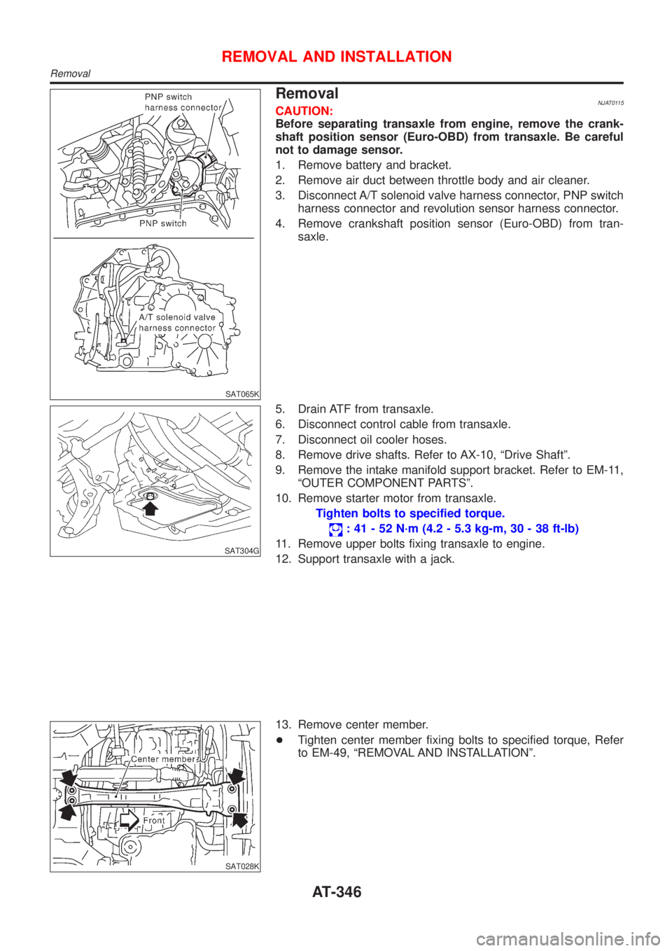
SAT065K
RemovalNJAT0115CAUTION:
Before separating transaxle from engine, remove the crank-
shaft position sensor (Euro-OBD) from transaxle. Be careful
not to damage sensor.
1. Remove battery and bracket.
2. Remove air duct between throttle body and air cleaner.
3. Disconnect A/T solenoid valve harness connector, PNP switch
harness connector and revolution sensor harness connector.
4. Remove crankshaft position sensor (Euro-OBD) from tran-
saxle.
SAT304G
5. Drain ATF from transaxle.
6. Disconnect control cable from transaxle.
7. Disconnect oil cooler hoses.
8. Remove drive shafts. Refer to AX-10, ªDrive Shaftº.
9. Remove the intake manifold support bracket. Refer to EM-11,
ªOUTER COMPONENT PARTSº.
10. Remove starter motor from transaxle.
Tighten bolts to specified torque.
: 41 - 52 N´m (4.2 - 5.3 kg-m, 30 - 38 ft-lb)
11. Remove upper bolts fixing transaxle to engine.
12. Support transaxle with a jack.
SAT028K
13. Remove center member.
+Tighten center member fixing bolts to specified torque, Refer
to EM-49, ªREMOVAL AND INSTALLATIONº.
REMOVAL AND INSTALLATION
Removal
AT-346
Page 1636 of 2493
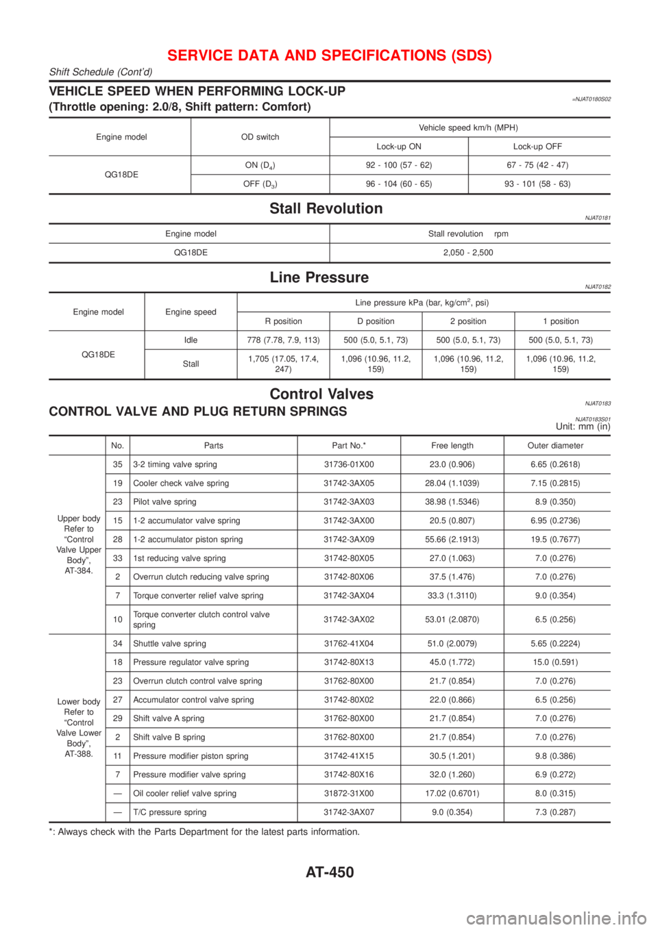
VEHICLE SPEED WHEN PERFORMING LOCK-UP=NJAT0180S02(Throttle opening: 2.0/8, Shift pattern: Comfort)
Engine model OD switchVehicle speed km/h (MPH)
Lock-up ON Lock-up OFF
QG18DEON (D
4) 92 - 100 (57 - 62) 67 - 75 (42 - 47)
OFF (D
3) 96 - 104 (60 - 65) 93 - 101 (58 - 63)
Stall RevolutionNJAT0181
Engine model Stall revolution rpm
QG18DE 2,050 - 2,500
Line PressureNJAT0182
Engine model Engine speedLine pressure kPa (bar, kg/cm
2, psi)
R position D position 2 position 1 position
QG18DEIdle 778 (7.78, 7.9, 113) 500 (5.0, 5.1, 73) 500 (5.0, 5.1, 73) 500 (5.0, 5.1, 73)
Stall1,705 (17.05, 17.4,
247)1,096 (10.96, 11.2,
159)1,096 (10.96, 11.2,
159)1,096 (10.96, 11.2,
159)
Control ValvesNJAT0183CONTROL VALVE AND PLUG RETURN SPRINGSNJAT0183S01Unit: mm (in)
No. Parts Part No.* Free length Outer diameter
Upper body
Refer to
ªControl
Valve Upper
Bodyº,
AT-384.35 3-2 timing valve spring 31736-01X00 23.0 (0.906) 6.65 (0.2618)
19 Cooler check valve spring 31742-3AX05 28.04 (1.1039) 7.15 (0.2815)
23 Pilot valve spring 31742-3AX03 38.98 (1.5346) 8.9 (0.350)
15 1-2 accumulator valve spring 31742-3AX00 20.5 (0.807) 6.95 (0.2736)
28 1-2 accumulator piston spring 31742-3AX09 55.66 (2.1913) 19.5 (0.7677)
33 1st reducing valve spring 31742-80X05 27.0 (1.063) 7.0 (0.276)
2 Overrun clutch reducing valve spring 31742-80X06 37.5 (1.476) 7.0 (0.276)
7 Torque converter relief valve spring 31742-3AX04 33.3 (1.3110) 9.0 (0.354)
10Torque converter clutch control valve
spring31742-3AX02 53.01 (2.0870) 6.5 (0.256)
Lower body
Refer to
ªControl
Valve Lower
Bodyº,
AT-388.34 Shuttle valve spring 31762-41X04 51.0 (2.0079) 5.65 (0.2224)
18 Pressure regulator valve spring 31742-80X13 45.0 (1.772) 15.0 (0.591)
23 Overrun clutch control valve spring 31762-80X00 21.7 (0.854) 7.0 (0.276)
27 Accumulator control valve spring 31742-80X02 22.0 (0.866) 6.5 (0.256)
29 Shift valve A spring 31762-80X00 21.7 (0.854) 7.0 (0.276)
2 Shift valve B spring 31762-80X00 21.7 (0.854) 7.0 (0.276)
11 Pressure modifier piston spring 31742-41X15 30.5 (1.201) 9.8 (0.386)
7 Pressure modifier valve spring 31742-80X16 32.0 (1.260) 6.9 (0.272)
Ð Oil cooler relief valve spring 31872-31X00 17.02 (0.6701) 8.0 (0.315)
Ð T/C pressure spring 31742-3AX07 9.0 (0.354) 7.3 (0.287)
*: Always check with the Parts Department for the latest parts information.
SERVICE DATA AND SPECIFICATIONS (SDS)
Shift Schedule (Cont'd)
AT-450
Page 1646 of 2493
SBR686C
Precautions
PRECAUTIONSNJAX0001+When installing rubber parts, final tightening must be car-
ried out under unladen condition* with tires on ground.
*: Fuel, radiator coolant and engine oil full. Spare tire, jack,
hand tools and mats in designated positions.
+After installing removed suspension parts, check wheel
alignment and adjust if necessary.
+Use flare nut wrench when removing or installing brake
tubes.
+Always torque brake lines when installing.
Preparation
SPECIAL SERVICE TOOLSNJAX0002
Tool number
Tool nameDescription
HT72520000
Ball joint remover
NT146
Removing tie-rod outer end and lower ball joint
KV38106800
Differential side oil seal
protector
NT147
Installing drive shaft
KV38106800
COMMERCIAL SERVICE TOOLSNJAX0003
Tool name Description
1 Flare nut crowfoot
2 Torque wrench
NT360
Removing and installing each brake piping
a: 10 mm (0.39 in)
FRONT AXLE
Precautions
AX-2
Page 1651 of 2493
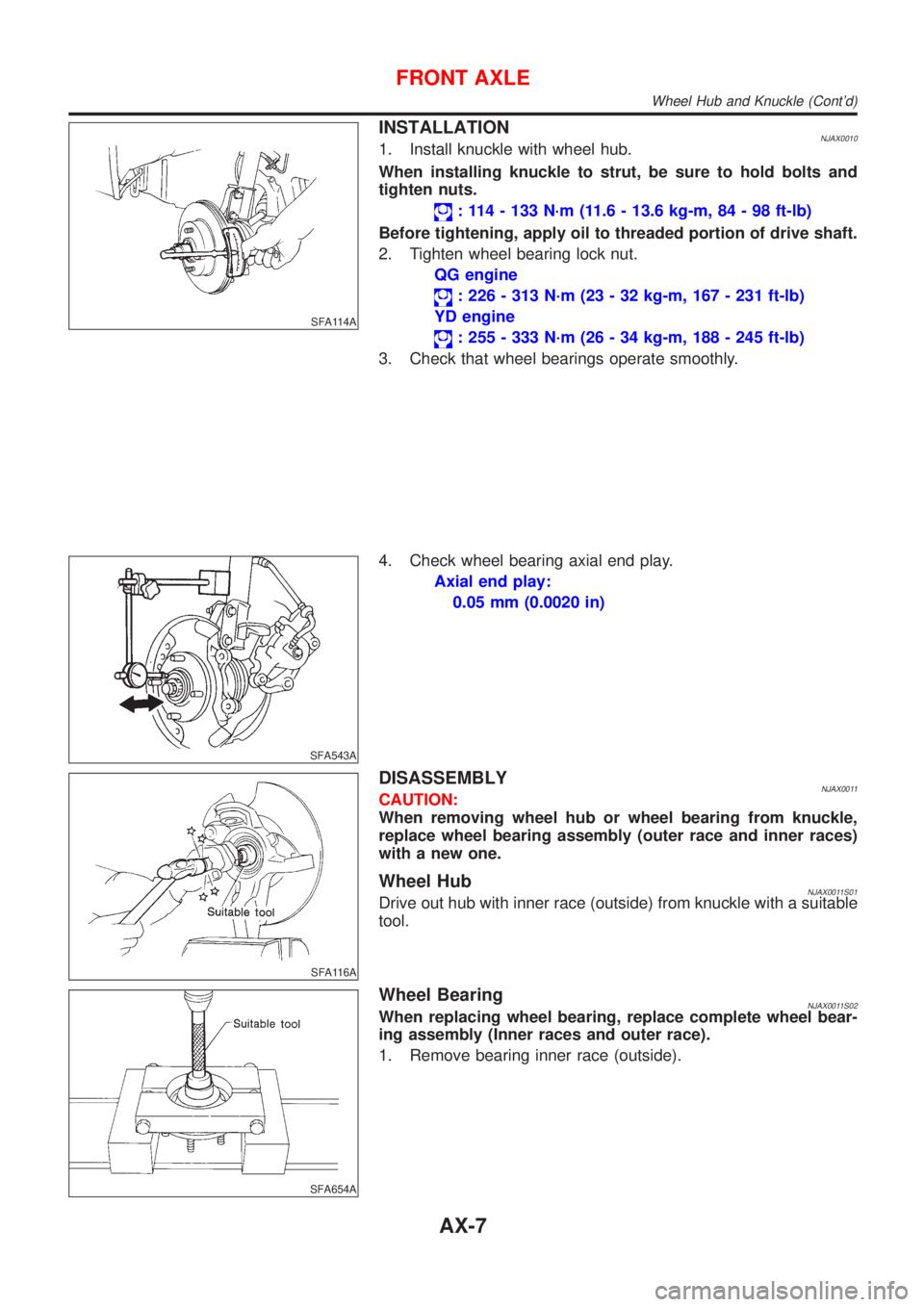
SFA114A
INSTALLATIONNJAX00101. Install knuckle with wheel hub.
When installing knuckle to strut, be sure to hold bolts and
tighten nuts.
: 114 - 133 N´m (11.6 - 13.6 kg-m, 84 - 98 ft-lb)
Before tightening, apply oil to threaded portion of drive shaft.
2. Tighten wheel bearing lock nut.
QG engine
: 226 - 313 N´m (23 - 32 kg-m, 167 - 231 ft-lb)
YD engine
: 255 - 333 N´m (26 - 34 kg-m, 188 - 245 ft-lb)
3. Check that wheel bearings operate smoothly.
SFA543A
4. Check wheel bearing axial end play.
Axial end play:
0.05 mm (0.0020 in)
SFA116A
DISASSEMBLYNJAX0011CAUTION:
When removing wheel hub or wheel bearing from knuckle,
replace wheel bearing assembly (outer race and inner races)
with a new one.
Wheel HubNJAX0011S01Drive out hub with inner race (outside) from knuckle with a suitable
tool.
SFA654A
Wheel BearingNJAX0011S02When replacing wheel bearing, replace complete wheel bear-
ing assembly (Inner races and outer race).
1. Remove bearing inner race (outside).
FRONT AXLE
Wheel Hub and Knuckle (Cont'd)
AX-7
Page 1666 of 2493
SBR686C
Precautions
PRECAUTIONSNJAX0022+When installing each rubber part, final tightening must be
carried out under unladen condition* with tires on ground.
*: Fuel, radiator coolant and engine oil full. Spare tire, jack,
hand tools and mats in designated positions.
+Use flare nut wrench when removing or installing brake
tubes.
+After installing removed suspension parts, check wheel
alignment.
+Do not jack up at the trailing arm and lateral link.
+Always torque brake lines when installing.
Preparation
SPECIAL SERVICE TOOLSNJAX0032
Tool number
Tool nameDescription
KV40104710
Drift
NT474
Install ABS sensor rotor
a: 76.3 mm (3.004 in) dia.
b: 67.9 mm (2.673 in) dia.
ST3072000
Drift
NT115
Install ABS sensor rotor
a: 77 mm (3.03 in) dia.
b: 55.5 mm (2.185 in) dia.
COMMERCIAL SERVICE TOOLSNJAX0024
Tool name Description
1 Flare nut crowfoot
2 Torque wrench
NT360
Removing and installing brake piping
a: 10 mm (0.39 in)
REAR AXLE
Precautions
AX-22
Page 1674 of 2493
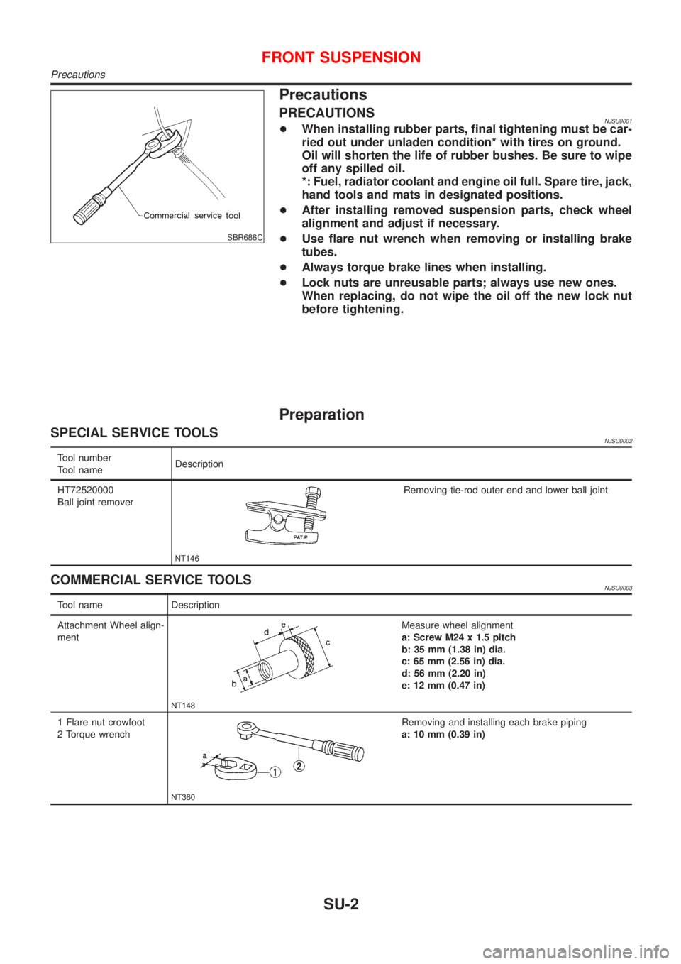
SBR686C
Precautions
PRECAUTIONSNJSU0001+When installing rubber parts, final tightening must be car-
ried out under unladen condition* with tires on ground.
Oil will shorten the life of rubber bushes. Be sure to wipe
off any spilled oil.
*: Fuel, radiator coolant and engine oil full. Spare tire, jack,
hand tools and mats in designated positions.
+After installing removed suspension parts, check wheel
alignment and adjust if necessary.
+Use flare nut wrench when removing or installing brake
tubes.
+Always torque brake lines when installing.
+Lock nuts are unreusable parts; always use new ones.
When replacing, do not wipe the oil off the new lock nut
before tightening.
Preparation
SPECIAL SERVICE TOOLSNJSU0002
Tool number
Tool nameDescription
HT72520000
Ball joint remover
NT146
Removing tie-rod outer end and lower ball joint
COMMERCIAL SERVICE TOOLSNJSU0003
Tool name Description
Attachment Wheel align-
ment
NT148
Measure wheel alignment
a: Screw M24 x 1.5 pitch
b: 35 mm (1.38 in) dia.
c: 65 mm (2.56 in) dia.
d: 56 mm (2.20 in)
e: 12 mm (0.47 in)
1 Flare nut crowfoot
2 Torque wrench
NT360
Removing and installing each brake piping
a: 10 mm (0.39 in)
FRONT SUSPENSION
Precautions
SU-2
Page 1678 of 2493
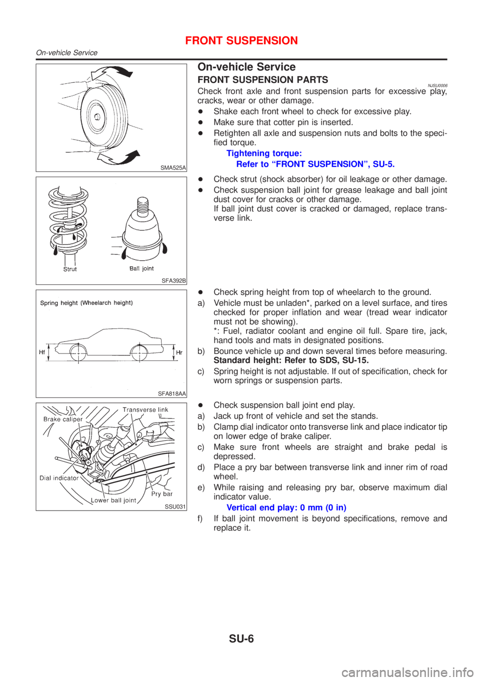
SMA525A
On-vehicle Service
FRONT SUSPENSION PARTSNJSU0006Check front axle and front suspension parts for excessive play,
cracks, wear or other damage.
+Shake each front wheel to check for excessive play.
+Make sure that cotter pin is inserted.
+Retighten all axle and suspension nuts and bolts to the speci-
fied torque.
Tightening torque:
Refer to ªFRONT SUSPENSIONº, SU-5.
SFA392B
+Check strut (shock absorber) for oil leakage or other damage.
+Check suspension ball joint for grease leakage and ball joint
dust cover for cracks or other damage.
If ball joint dust cover is cracked or damaged, replace trans-
verse link.
SFA818AA
+Check spring height from top of wheelarch to the ground.
a) Vehicle must be unladen*, parked on a level surface, and tires
checked for proper inflation and wear (tread wear indicator
must not be showing).
*: Fuel, radiator coolant and engine oil full. Spare tire, jack,
hand tools and mats in designated positions.
b) Bounce vehicle up and down several times before measuring.
Standard height: Refer to SDS, SU-15.
c) Spring height is not adjustable. If out of specification, check for
worn springs or suspension parts.
SSU031
+Check suspension ball joint end play.
a) Jack up front of vehicle and set the stands.
b) Clamp dial indicator onto transverse link and place indicator tip
on lower edge of brake caliper.
c) Make sure front wheels are straight and brake pedal is
depressed.
d) Place a pry bar between transverse link and inner rim of road
wheel.
e) While raising and releasing pry bar, observe maximum dial
indicator value.
Vertical end play: 0 mm (0 in)
f) If ball joint movement is beyond specifications, remove and
replace it.
FRONT SUSPENSION
On-vehicle Service
SU-6