Page 764 of 2493

3 DETECT MALFUNCTIONING PART
Check the following.
+10A fuse
+15A fuse
+Harness for open or short between fuse and fuel pump relay
©Repair harness or connectors.
4 CHECK POWER GROUND CIRCUIT
1. Turn ignition switch ªOFFº.
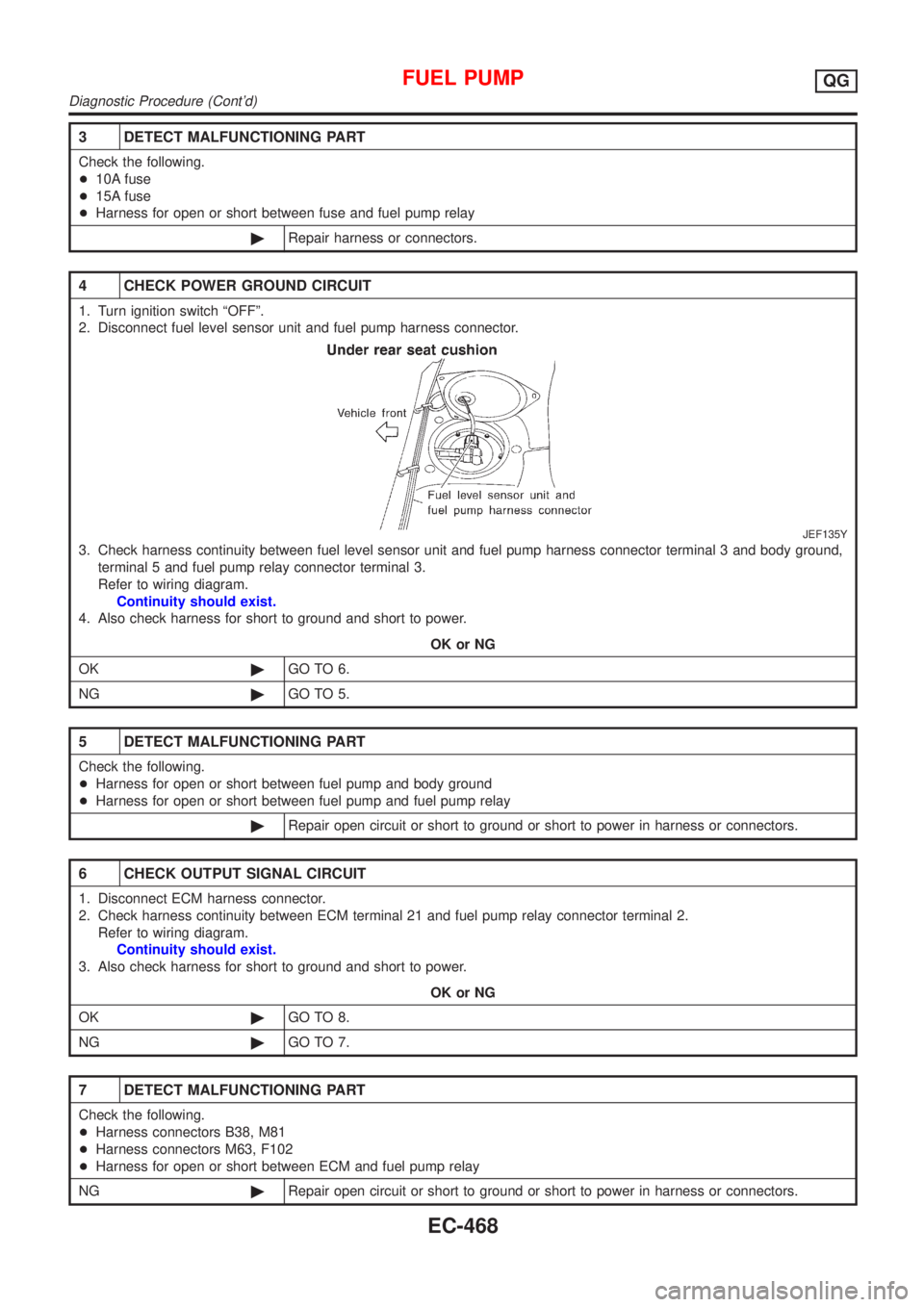
2. Disconnect fuel level sensor unit and fuel pump harness connector.
JEF135Y
3. Check harness continuity between fuel level sensor unit and fuel pump harness connector terminal 3 and body ground,
terminal 5 and fuel pump relay connector terminal 3.
Refer to wiring diagram.
Continuity should exist.
4. Also check harness for short to ground and short to power.
OK or NG
OK©GO TO 6.
NG©GO TO 5.
5 DETECT MALFUNCTIONING PART
Check the following.
+Harness for open or short between fuel pump and body ground
+Harness for open or short between fuel pump and fuel pump relay
©Repair open circuit or short to ground or short to power in harness or connectors.
6 CHECK OUTPUT SIGNAL CIRCUIT
1. Disconnect ECM harness connector.
2. Check harness continuity between ECM terminal 21 and fuel pump relay connector terminal 2.
Refer to wiring diagram.
Continuity should exist.
3. Also check harness for short to ground and short to power.
OK or NG
OK©GO TO 8.
NG©GO TO 7.
7 DETECT MALFUNCTIONING PART
Check the following.
+Harness connectors B38, M81
+Harness connectors M63, F102
+Harness for open or short between ECM and fuel pump relay
NG©Repair open circuit or short to ground or short to power in harness or connectors.
FUEL PUMPQG
Diagnostic Procedure (Cont'd)
EC-468
Page 767 of 2493
Wiring DiagramNJEC0450
YEC002A
POWER STEERING OIL PRESSURE SWITCHQG
Wiring Diagram
EC-471
Page 769 of 2493

4 CHECK GROUND CIRCUIT
1. Turn ignition switch ªOFFº.
2. Disconnect power steering oil pressure switch harness connector.
3. Check harness continuity between power steering oil pressure switch harness terminal 2 and engine ground.
Refer to wiring diagram.
Continuity should exist.
4. Also check harness for short to ground and short to power.
OK or NG
OK©GO TO 5.
NG©Repair open circuit or short to ground or short to power in harness or connectors.
5 CHECK INPUT SIGNAL CIRCUIT
1. Disconnect ECM harness connector.
2. Check harness continuity between ECM terminal 46 and power steering oil pressure switch harness terminal 1.
Refer to wiring diagram.
Continuity should exist.
3. Also check harness for short to ground and short to power.
OK or NG
OK©GO TO 7.
NG©GO TO 6.
6 DETECT MALFUNCTIONING PART
Check the harness for open or short between ECM and power steering oil pressure switch.
©Repair open circuit or short to ground or short to power in harness or connectors.
7 CHECK POWER STEERING OIL PRESSURE SWITCH
Refer to ªComponent Inspectionº, EC-473.
OK or NG
OK©GO TO 8.
NG©Replace power steering oil pressure switch.
8 CHECK INTERMITTENT INCIDENT
Perform ªTROUBLE DIAGNOSIS FOR INTERMITTENT INCIDENTº, EC-144.
©INSPECTION END
Component InspectionNJEC0455POWER STEERING OIL PRESSURE SWITCHNJEC0455S011. Disconnect power steering oil pressure switch harness con-
nector then start engine.
2. Check continuity between terminals 1 and 2.
Refer to wiring diagram.
Conditions Continuity
Steering wheel is being fully turned. Yes
Steering wheel is not being turned. No
POWER STEERING OIL PRESSURE SWITCHQG
Diagnostic Procedure (Cont'd)
EC-473
Page 772 of 2493
Wiring DiagramNJEC0582
YEC003A
REFRIGERANT PRESSURE SENSORQG
Wiring Diagram
EC-476
Page 774 of 2493

3 DETECT MALFUNCTIONING PART
Check the following.
+Harness connectors E75, F36
+Joint connector-6
+Harness for open or short between ECM and refrigerant pressure sensor
©Repair harness or connectors.
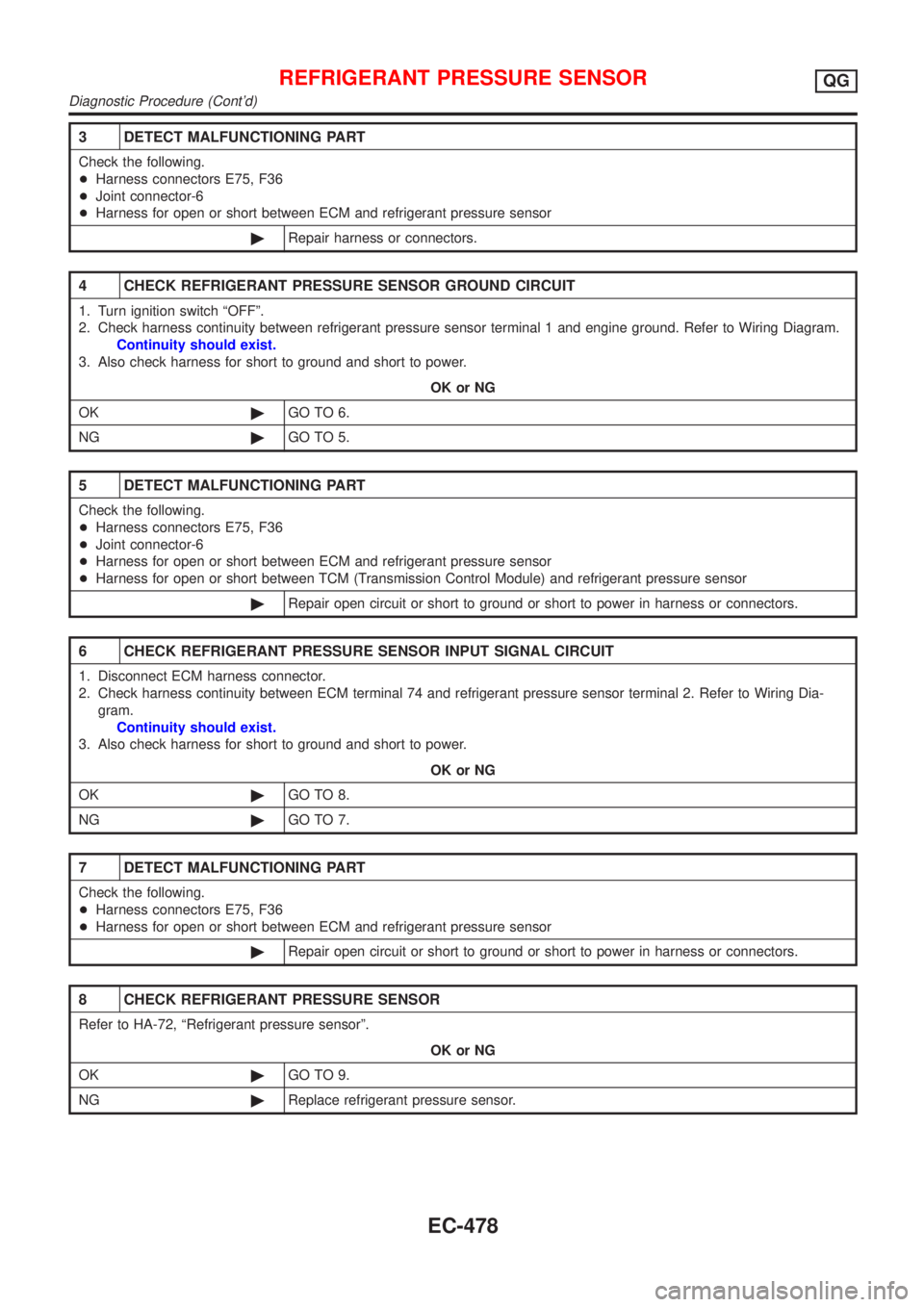
4 CHECK REFRIGERANT PRESSURE SENSOR GROUND CIRCUIT
1. Turn ignition switch ªOFFº.
2. Check harness continuity between refrigerant pressure sensor terminal 1 and engine ground. Refer to Wiring Diagram.
Continuity should exist.
3. Also check harness for short to ground and short to power.
OK or NG
OK©GO TO 6.
NG©GO TO 5.
5 DETECT MALFUNCTIONING PART
Check the following.
+Harness connectors E75, F36
+Joint connector-6
+Harness for open or short between ECM and refrigerant pressure sensor
+Harness for open or short between TCM (Transmission Control Module) and refrigerant pressure sensor
©Repair open circuit or short to ground or short to power in harness or connectors.
6 CHECK REFRIGERANT PRESSURE SENSOR INPUT SIGNAL CIRCUIT
1. Disconnect ECM harness connector.
2. Check harness continuity between ECM terminal 74 and refrigerant pressure sensor terminal 2. Refer to Wiring Dia-
gram.
Continuity should exist.
3. Also check harness for short to ground and short to power.
OK or NG
OK©GO TO 8.
NG©GO TO 7.
7 DETECT MALFUNCTIONING PART
Check the following.
+Harness connectors E75, F36
+Harness for open or short between ECM and refrigerant pressure sensor
©Repair open circuit or short to ground or short to power in harness or connectors.
8 CHECK REFRIGERANT PRESSURE SENSOR
Refer to HA-72, ªRefrigerant pressure sensorº.
OK or NG
OK©GO TO 9.
NG©Replace refrigerant pressure sensor.
REFRIGERANT PRESSURE SENSORQG
Diagnostic Procedure (Cont'd)
EC-478
Page 777 of 2493
Wiring DiagramNJEC0550
YEC004A
ELECTRICAL LOAD SIGNALQG
Wiring Diagram
EC-481
Page 778 of 2493
YEC005A
ELECTRICAL LOAD SIGNALQG
Wiring Diagram (Cont'd)
EC-482
Page 781 of 2493

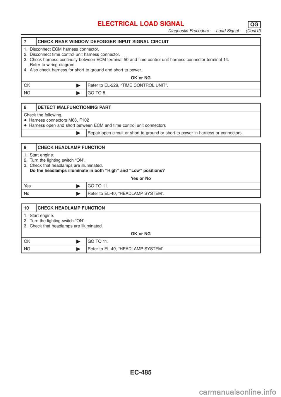
7 CHECK REAR WINDOW DEFOGGER INPUT SIGNAL CIRCUIT
1. Disconnect ECM harness connector.
2. Disconnect time control unit harness connector.
3. Check harness continuity between ECM terminal 50 and time control unit harness connector terminal 14.
Refer to wiring diagram.
4. Also check harness for short to ground and short to power.
OK or NG
OK©Refer to EL-229, ªTIME CONTROL UNITº.
NG©GO TO 8.
8 DETECT MALFUNCTIONING PART
Check the following.
+Harness connectors M63, F102
+Harness open and short between ECM and time control unit connectors
©Repair open circuit or short to ground or short to power in harness or connectors.
9 CHECK HEADLAMP FUNCTION
1. Start engine.
2. Turn the lighting switch ªONº.
3. Check that headlamps are illuminated.
Do the headlamps illuminate in both ªHighº and ªLowº positions?
YesorNo
Ye s©GO TO 11.
No©Refer to EL-40, ªHEADLAMP SYSTEMº.
10 CHECK HEADLAMP FUNCTION
1. Start engine.
2. Turn the lighting switch ªONº.
3. Check that headlamps are illuminated.
OK or NG
OK©GO TO 11.
NG©Refer to EL-40, ªHEADLAMP SYSTEMº.
ELECTRICAL LOAD SIGNALQG
Diagnostic Procedure Ð Load Signal Ð (Cont'd)
EC-485