Page 731 of 2493

4 CHECK POWER SUPPLY
1. Turn ignition switch ªOFFº.
2. Disconnect intake valve timing control solenoid valve harness connector.
SEF149X
3. Turn ignition switch ªONº.
4. Check voltage between terminal 1 and engine ground with CONSULT-II or tester.
SEF619X
OK or NG
OK©GO TO 6.
NG©GO TO 5.
5 DETECT MALFUNCTIONING PART
Check the following.
+Harness connectors M169, F113
+10A fuse
+Harness for open or short between valve timing control solenoid valve and fuse
©Repair harness or connectors.
6 CHECK OUTPUT SIGNAL CIRCUIT
1. Turn ignition switch ªOFFº.
2. Disconnect ECM harness connector.
3. Check harness continuity between ECM terminal 1 and intake valve timing control solenoid valve harness connector
terminal 2. Refer to wiring diagram.
Continuity should exist.
4. Also check harness for short to ground and short to power.
OK or NG
OK©GO TO 7.
NG©Repair open circuit or short to ground to short to power or connectors.
INTAKE VALVE TIMING CONTROL SOLENOID VALVEQG
Diagnostic Procedure (Cont'd)
EC-435
Page 734 of 2493
Wiring DiagramNJEC1777
YEC994
A/T COMMUNICATION LINEQG
Wiring Diagram
EC-438
Page 735 of 2493
Diagnostic ProcedureNJEC1778
1 CHECK OVERALL FUNCTION
1. Start engine and warm it up to normal operating temperature.
2. Check the voltage between ECM terminals 10, 19, 54, 55, 56 and ground.
SEF791Z
OK or NG
OK©INSPECTION END
NG©GO TO 2.
2 CHECK A/T CONTROL INPUT SIGNAL CIRCUIT FOR OPEN
1. Turn ignition switch ªOFFº.
2. Disconnect ECM harness connector and TCM (Transmission Control Module) harness connector.
SEF116Y
3. Check harness continuity between the following terminals.
YEC057A
Refer to Wiring Diagram.
Continuity should exist.
OK or NG
OK©GO TO 3.
NG©Repair harness or connectors.
A/T COMMUNICATION LINEQG
Diagnostic Procedure
EC-439
Page 736 of 2493
3 CHECK A/T CONTROL INPUT SIGNAL CIRCUIT FOR SHORT
1. Check harness continuity between ECM terminals 10, 19, 54, 55, 56 and ground.
Refer to Wiring Diagram.
Continuity should not exist.
2. Also check harness for short to power.
OK or NG
OK©GO TO 4.
NG©Repair short to ground or short to power in harness or connectos.
4 CHECK INTERMITTENT INCIDENT
Refer to ªTROUBLE DIAGNOSIS FOR INTERMITTENT INCIDENTº, EC-144.
©INSPECTION END
A/T COMMUNICATION LINEQG
Diagnostic Procedure (Cont'd)
EC-440
Page 738 of 2493
Wiring DiagramNJEC1782
YEC995
PARK/NEUTRAL POSITION (PNP) SWITCHQG
Wiring Diagram
EC-442
Page 740 of 2493

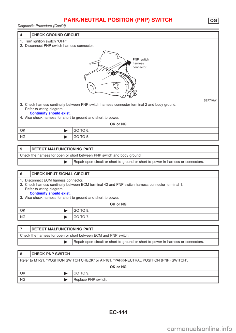
4 CHECK GROUND CIRCUIT
1. Turn ignition switch ªOFFº.
2. Disconnect PNP switch harness connector.
SEF740W
3. Check harness continuity between PNP switch harness connector terminal 2 and body ground.
Refer to wiring diagram.
Continuity should exist.
4. Also check harness for short to ground and short to power.
OK or NG
OK©GO TO 6.
NG©GO TO 5.
5 DETECT MALFUNCTIONING PART
Check the harness for open or short between PNP switch and body ground.
©Repair open circuit or short to ground or short to power in harness or connectors.
6 CHECK INPUT SIGNAL CIRCUIT
1. Disconnect ECM harness connector.
2. Check harness continuity between ECM terminal 42 and PNP switch harness connector terminal 1.
Refer to wiring diagram.
Continuity should exist.
3. Also check harness for short to ground and short to power.
OK or NG
OK©GO TO 8.
NG©GO TO 7.
7 DETECT MALFUNCTIONING PART
Check the harness for open or short between ECM and PNP switch.
©Repair open circuit or short to ground or short to power in harness or connectors.
8 CHECK PNP SWITCH
Refer to MT-21, ªPOSITION SWITCH CHECKº or AT-181, ªPARK/NEUTRAL POSITION (PNP) SWITCHº.
OK or NG
OK©GO TO 9.
NG©Replace PNP switch.
PARK/NEUTRAL POSITION (PNP) SWITCHQG
Diagnostic Procedure (Cont'd)
EC-444
Page 743 of 2493
Wiring DiagramNJEC0434
YEC996
INJECTORQG
Wiring Diagram
EC-447
Page 745 of 2493

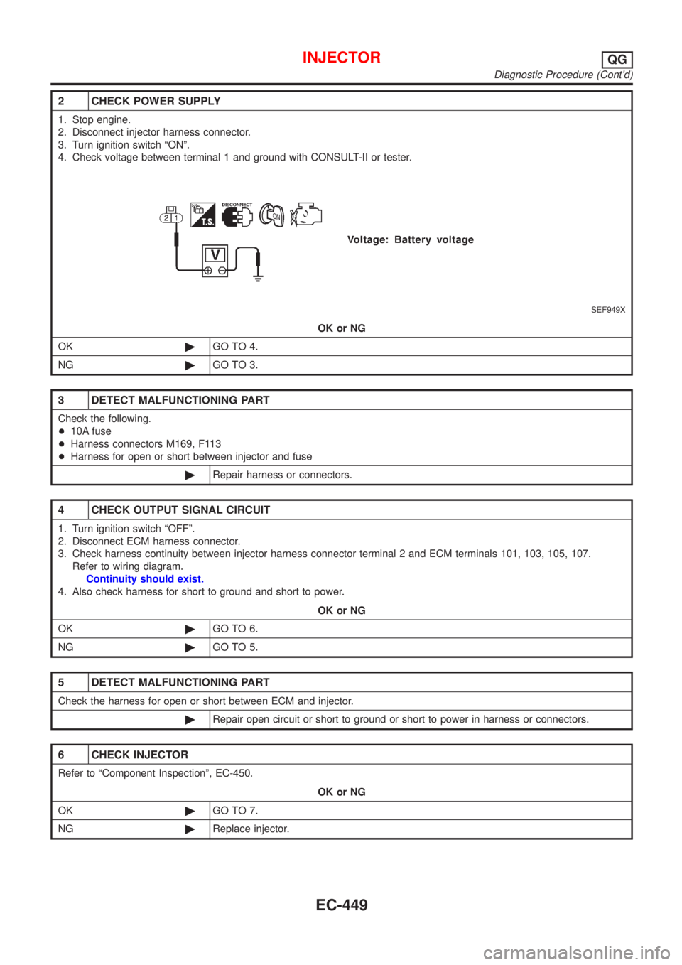
2 CHECK POWER SUPPLY
1. Stop engine.
2. Disconnect injector harness connector.
3. Turn ignition switch ªONº.
4. Check voltage between terminal 1 and ground with CONSULT-II or tester.
SEF949X
OK or NG
OK©GO TO 4.
NG©GO TO 3.
3 DETECT MALFUNCTIONING PART
Check the following.
+10A fuse
+Harness connectors M169, F113
+Harness for open or short between injector and fuse
©Repair harness or connectors.
4 CHECK OUTPUT SIGNAL CIRCUIT
1. Turn ignition switch ªOFFº.
2. Disconnect ECM harness connector.
3. Check harness continuity between injector harness connector terminal 2 and ECM terminals 101, 103, 105, 107.
Refer to wiring diagram.
Continuity should exist.
4. Also check harness for short to ground and short to power.
OK or NG
OK©GO TO 6.
NG©GO TO 5.
5 DETECT MALFUNCTIONING PART
Check the harness for open or short between ECM and injector.
©Repair open circuit or short to ground or short to power in harness or connectors.
6 CHECK INJECTOR
Refer to ªComponent Inspectionº, EC-450.
OK or NG
OK©GO TO 7.
NG©Replace injector.
INJECTORQG
Diagnostic Procedure (Cont'd)
EC-449