Page 783 of 2493

Diagnostic Procedure Ð Heater Control Panel
(Fan Switch) Ð
NJEC0585
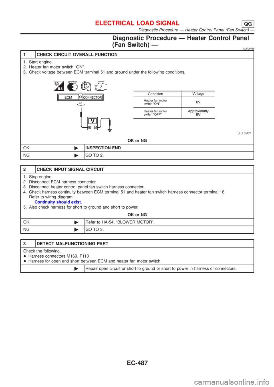
1 CHECK CIRCUIT OVERALL FUNCTION
1. Start engine.
2. Heater fan motor switch ªONº.
3. Check voltage between ECM terminal 51 and ground under the following conditions.
SEF620Y
OK or NG
OK©INSPECTION END
NG©GO TO 2.
2 CHECK INPUT SIGNAL CIRCUIT
1. Stop engine.
2. Disconnect ECM harness connector.
3. Disconnect heater control panel fan switch harness connector.
4. Check harness continuity between ECM terminal 51 and heater fan switch harness connector terminal 18.
Refer to wiring diagram.
Continuity should exist.
5. Also check harness for short to ground and short to power.
OK or NG
OK©Refer to HA-54, ªBLOWER MOTORº.
NG©GO TO 3.
3 DETECT MALFUNCTIONING PART
Check the following.
+Harness connectors M169, F113
+Harness for open and short between ECM and heater fan motor switch
©Repair open circuit or short to ground or short to power in harness or connectors.
ELECTRICAL LOAD SIGNALQG
Diagnostic Procedure Ð Heater Control Panel (Fan Switch) Ð
EC-487
Page 784 of 2493
Wiring DiagramNJEC0466
YEC006A
MI & DATA LINK CONNECTORSQG
Wiring Diagram
EC-488
Page 793 of 2493
SEF348N
+When measuring ECM signals with a circuit tester, never
allow the two tester probes to contact.
Accidental contact of probes will cause a short circuit and
damage the ECM power transistor.
+Do not use ECM ground terminals when measuring input/
output voltage. Doing so may result in damage to the
ECM's transistor. Use a ground other than ECM terminals,
such as the ground.
+Install the break-out box between ECM and ECM harness
connectors when measuring ECM input/output voltage.
Wiring Diagrams and Trouble DiagnosisNJEC0604When you read Wiring diagrams, refer to the following:
+GI-12, ªHOW TO READ WIRING DIAGRAMSº
+EL-10, ªPOWER SUPPLY ROUTINGº for power distribution circuit
When you perform trouble diagnosis, refer to the following:
+GI-32, ªHOW TO FOLLOW TEST GROUPS IN TROUBLE DIAGNOSESº
+GI-21, ªHOW TO PERFORM EFFICIENT DIAGNOSIS FOR AN ELECTRICAL INCIDENTº
PRECAUTIONSYD
Precautions (Cont'd)
EC-497
Page 857 of 2493
WIRING DIAGRAMNJEC0640
YEC009A
TROUBLE DIAGNOSIS FOR POWER SUPPLYYD
Main Power Supply and Ground Circuit (Cont'd)
EC-561
Page 858 of 2493

DIAGNOSTIC PROCEDURENJEC0641
1 INSPECTION START
Start engine.
Is engine running?
YesorNo
Ye s©GO TO 13.
No©GO TO 2.
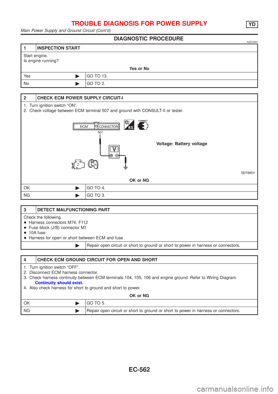
2 CHECK ECM POWER SUPPLY CIRCUIT-I
1. Turn ignition switch ªONº.
2. Check voltage between ECM terminal 507 and ground with CONSULT-II or tester.
SEF895Y
OK or NG
OK©GO TO 4.
NG©GO TO 3.
3 DETECT MALFUNCTIONING PART
Check the following.
+Harness connectors M74, F112
+Fuse block (J/B) connector M1
+10A fuse
+Harness for open or short between ECM and fuse
©Repair open circuit or short to ground or short to power in harness or connectors.
4 CHECK ECM GROUND CIRCUIT FOR OPEN AND SHORT
1. Turn ignition switch ªOFFº.
2. Disconnect ECM harness connector.
3. Check harness continuity between ECM terminals 104, 105, 106 and engine ground. Refer to Wiring Diagram.
Continuity should exist.
4. Also check harness for short to ground and short to power.
OK or NG
OK©GO TO 5.
NG©Repair open circuit or short to ground or short to power in harness or connectors.
TROUBLE DIAGNOSIS FOR POWER SUPPLYYD
Main Power Supply and Ground Circuit (Cont'd)
EC-562
Page 860 of 2493

8 CHECK OUTPUT SIGNAL CIRCUIT FOR OPEN AND SHORT
1. Disconnect ECM harness connector.
2. Check harness continuity between ECM terminal 325 and ECM relay terminal 2. Refer to Wiring Diagram.
Continuity should exist.
3. Also check harness for short to ground and short to power.
OK or NG
OK©GO TO 10.
NG©GO TO 9.
9 DETECT MALFUNCTIONING PART
Check the following.
+Harness connectors E174, M159
+Harness connectors M63, F102
+Harness for open or short between ECM and ECM relay
©Repair open circuit or short to ground or short to power in harness or connectors.
10 CHECK ECM POWER SUPPLY CIRCUIT-IV
1. Check harness continuity between ECM terminals 107, 108, 109 and ECM relay terminal 7. Refer to Wiring Diagram.
Continuity should exist.
2. Also check harness for short to ground and short to power.
OK or NG
OK©GO TO 12.
NG©GO TO 11.
11 DETECT MALFUNCTIONING PART
Check the following.
+Harness connectors E75, F36
+Harness for open or short between ECM and ECM relay
©Repair open circuit or short to ground or short to power in harness or connectors.
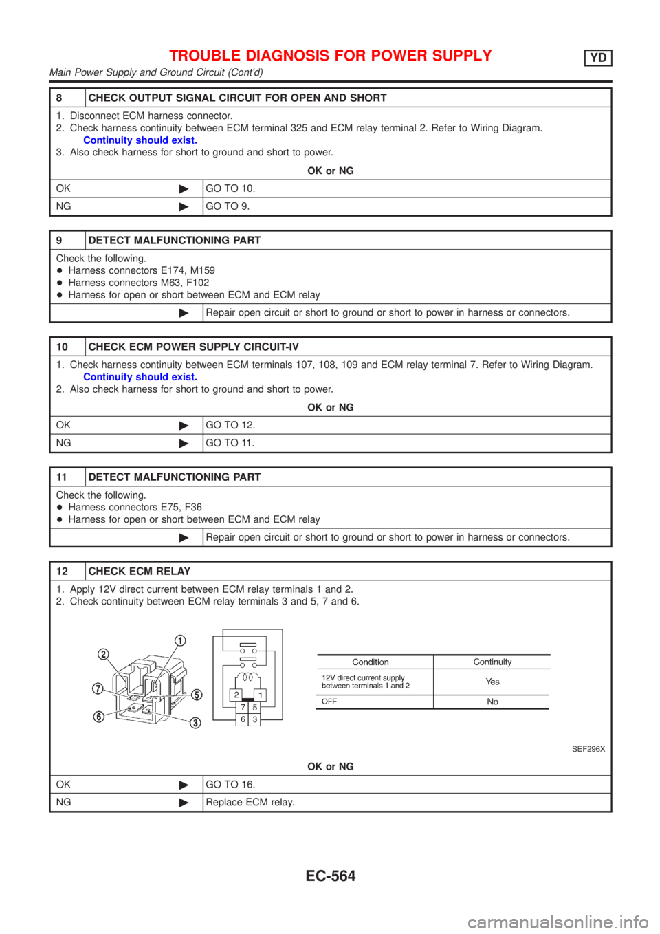
12 CHECK ECM RELAY
1. Apply 12V direct current between ECM relay terminals 1 and 2.
2. Check continuity between ECM relay terminals 3 and 5, 7 and 6.
SEF296X
OK or NG
OK©GO TO 16.
NG©Replace ECM relay.
TROUBLE DIAGNOSIS FOR POWER SUPPLYYD
Main Power Supply and Ground Circuit (Cont'd)
EC-564
Page 861 of 2493

13 CHECK ECM POWER SUPPLY CIRCUIT-V
1. Turn ignition switch ªOFFº.
2. Disconnect ECM relay. (For ECM relay location, refer to ªEngine Control Component Parts Locationº.)
3. Disconnect ECM harness connector.
4. Check harness continuity between ECM terminals 107, 108, 109 and ECM relay terminal 7. Refer to Wiring Diagram.
Continuity should exist.
5. Also check harness for short to ground and short to power.
OK or NG
OK©GO TO 15.
NG©GO TO 14.
14 DETECT MALFUNCTIONING PART
Check the following.
+Harness connectors E75, F36
+Harness for open or short between ECM and ECM relay
©Repair open circuit or short to ground or short to power in harness or connectors.
15 CHECK ECM GROUND CIRCUIT FOR OPEN AND SHORT
1. Check harness continuity between ECM terminals 104, 105, 106 and engine ground. Refer to Wiring Diagram.
Continuity should exist.
2. Also check harness for short to ground and short to power.
OK or NG
OK©GO TO 16.
NG©Repair open circuit or short to ground or short to power in harness or connectors.
16 CHECK INTERMITTENT INCIDENT
Refer to ªTROUBLE DIAGNOSIS FOR INTERMITTENT INCIDENTº, EC-559.
©INSPECTION END
TROUBLE DIAGNOSIS FOR POWER SUPPLYYD
Main Power Supply and Ground Circuit (Cont'd)
EC-565
Page 864 of 2493
Wiring DiagramNJEC0647
YEC010A
DTC P0100 MASS AIR FLOW SENYD
Wiring Diagram
EC-568