Page 866 of 2493

3 CHECK MAFS GROUND CIRCUIT FOR OPEN AND SHORT
1. Turn ignition switch ªOFFº.
2. Loosen and retighten engine ground screws.
SEF380Y
3. Check harness continuity between mass air flow sensor terminal 3 and engine ground. Refer to Wiring Diagram.
Continuity should exist.
4. Also check harness for short to ground and short to power.
OK or NG
OK©GO TO 5.
NG©GO TO 4.
4 DETECT MALFUNCTIONING PART
Check harness for open or short between mass air flow sensor and ECM.
©Repair open circuit or short to ground or short to power in harness or connectors.
5 CHECK MAFS INPUT SIGNAL CIRCUIT FOR OPEN AND SHORT
1. Disconnect ECM harness connector.
2. Check harness continuity between mass air flow sensor terminal 1 and ECM terminal 224. Refer to Wiring Diagram.
Continuity should exist.
3. Also check harness for short to ground and short to power.
OK or NG
OK©GO TO 6.
NG©Repair open circuit or short to ground or short to power in harness or connectors.
DTC P0100 MASS AIR FLOW SENYD
Diagnostic Procedure (Cont'd)
EC-570
Page 870 of 2493
Wiring DiagramNJEC0652
YEC011A
DTC P0115 COOLANT TEMP SENYD
Wiring Diagram
EC-574
Page 871 of 2493
Diagnostic ProcedureNJEC0653
1 CHECK ECTS POWER SUPPLY CIRCUIT
1. Turn ignition switch ªOFFº.
2. Disconnect engine coolant temperature sensor harness connector.
SEF382Y
3. Turn ignition switch ªONº.
4. Check voltage between ECTS terminal 2 and ground with CONSULT-II or tester.
SEF401Y
OK or NG
OK©GO TO 2.
NG©Repair open circuit or short to ground or short to power in harness or connectors.
2 CHECK ECTS GROUND CIRCUIT FOR OPEN AND SHORT
1. Turn ignition switch ªOFFº.
2. Check harness continuity between ECTS terminal 1 and engine ground. Refer to Wiring Diagram.
Continuity should exist.
3. Also check harness for short to ground and short to power.
OK or NG
OK©GO TO 4.
NG©GO TO 3.
3 DETECT MALFUNCTIONING PART
Check the following harness for open or short between ECM and engine coolant temperature sensor.
©Repair open circuit or short to ground or short to power in harness or connectors.
DTC P0115 COOLANT TEMP SENYD
Diagnostic Procedure
EC-575
Page 875 of 2493
Wiring DiagramNJEC0684
YEC012A
DTC P0120 ACCEL POS SENSORYD
Wiring Diagram
EC-579
Page 879 of 2493

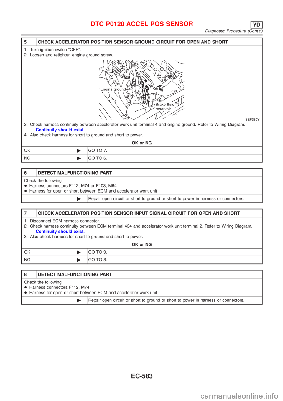
5 CHECK ACCELERATOR POSITION SENSOR GROUND CIRCUIT FOR OPEN AND SHORT
1. Turn ignition switch ªOFFº.
2. Loosen and retighten engine ground screw.
SEF380Y
3. Check harness continuity between accelerator work unit terminal 4 and engine ground. Refer to Wiring Diagram.
Continuity should exist.
4. Also check harness for short to ground and short to power.
OK or NG
OK©GO TO 7.
NG©GO TO 6.
6 DETECT MALFUNCTIONING PART
Check the following.
+Harness connectors F112, M74 or F103, M64
+Harness for open or short between ECM and accelerator work unit
©Repair open circuit or short to ground or short to power in harness or connectors.
7 CHECK ACCELERATOR POSITION SENSOR INPUT SIGNAL CIRCUIT FOR OPEN AND SHORT
1. Disconnect ECM harness connector.
2. Check harness continuity between ECM terminal 434 and accelerator work unit terminal 2. Refer to Wiring Diagram.
Continuity should exist.
3. Also check harness for short to ground and short to power.
OK or NG
OK©GO TO 9.
NG©GO TO 8.
8 DETECT MALFUNCTIONING PART
Check the following.
+Harness connectors F112, M74
+Harness for open or short between ECM and accelerator work unit
©Repair open circuit or short to ground or short to power in harness or connectors.
DTC P0120 ACCEL POS SENSORYD
Diagnostic Procedure (Cont'd)
EC-583
Page 881 of 2493

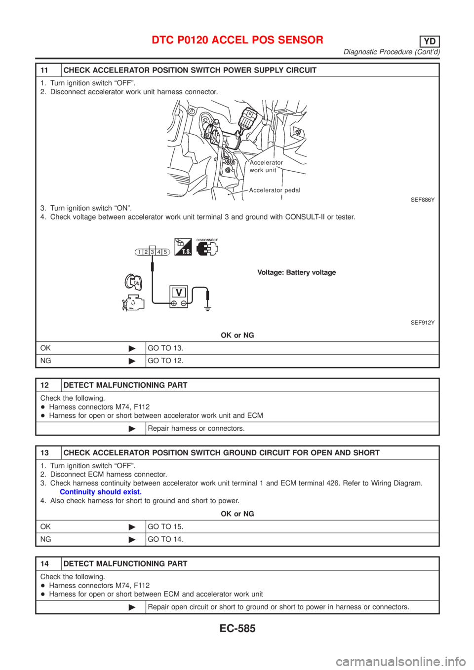
11 CHECK ACCELERATOR POSITION SWITCH POWER SUPPLY CIRCUIT
1. Turn ignition switch ªOFFº.
2. Disconnect accelerator work unit harness connector.
SEF886Y
3. Turn ignition switch ªONº.
4. Check voltage between accelerator work unit terminal 3 and ground with CONSULT-II or tester.
SEF912Y
OK or NG
OK©GO TO 13.
NG©GO TO 12.
12 DETECT MALFUNCTIONING PART
Check the following.
+Harness connectors M74, F112
+Harness for open or short between accelerator work unit and ECM
©Repair harness or connectors.
13 CHECK ACCELERATOR POSITION SWITCH GROUND CIRCUIT FOR OPEN AND SHORT
1. Turn ignition switch ªOFFº.
2. Disconnect ECM harness connector.
3. Check harness continuity between accelerator work unit terminal 1 and ECM terminal 426. Refer to Wiring Diagram.
Continuity should exist.
4. Also check harness for short to ground and short to power.
OK or NG
OK©GO TO 15.
NG©GO TO 14.
14 DETECT MALFUNCTIONING PART
Check the following.
+Harness connectors M74, F112
+Harness for open or short between ECM and accelerator work unit
©Repair open circuit or short to ground or short to power in harness or connectors.
DTC P0120 ACCEL POS SENSORYD
Diagnostic Procedure (Cont'd)
EC-585
Page 885 of 2493
Wiring DiagramNJEC0691
YEC013A
DTC P0335 CRANK POS SEN (TDC)YD
Wiring Diagram
EC-589
Page 886 of 2493

Diagnostic ProcedureNJEC0692
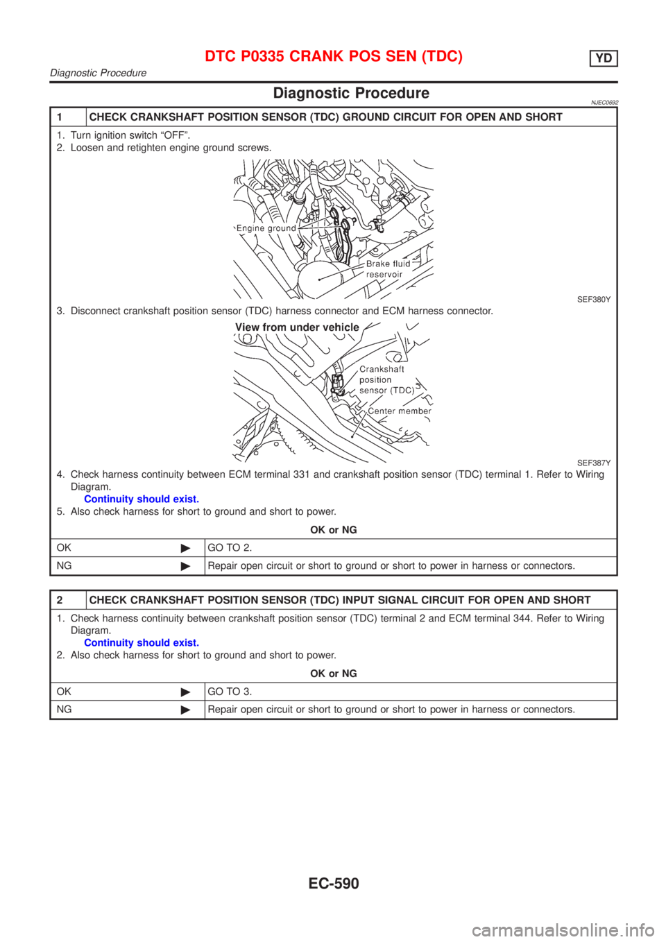
1 CHECK CRANKSHAFT POSITION SENSOR (TDC) GROUND CIRCUIT FOR OPEN AND SHORT
1. Turn ignition switch ªOFFº.
2. Loosen and retighten engine ground screws.
SEF380Y
3. Disconnect crankshaft position sensor (TDC) harness connector and ECM harness connector.
SEF387Y
4. Check harness continuity between ECM terminal 331 and crankshaft position sensor (TDC) terminal 1. Refer to Wiring
Diagram.
Continuity should exist.
5. Also check harness for short to ground and short to power.
OK or NG
OK©GO TO 2.
NG©Repair open circuit or short to ground or short to power in harness or connectors.
2 CHECK CRANKSHAFT POSITION SENSOR (TDC) INPUT SIGNAL CIRCUIT FOR OPEN AND SHORT
1. Check harness continuity between crankshaft position sensor (TDC) terminal 2 and ECM terminal 344. Refer to Wiring
Diagram.
Continuity should exist.
2. Also check harness for short to ground and short to power.
OK or NG
OK©GO TO 3.
NG©Repair open circuit or short to ground or short to power in harness or connectors.
DTC P0335 CRANK POS SEN (TDC)YD
Diagnostic Procedure
EC-590