Page 666 of 2493
Wiring DiagramNJEC1738
YEC985
INTAKE AIR TEMPERATURE SENSORQG
Wiring Diagram
EC-370
Page 668 of 2493

3 DETECT MALFUNCTIONING PART
Check harness for open or short between ECM and intake air temperature sensor.
©Repair harness or connectors.
4 CHECK GROUND CIRCUIT
1. Turn ignition switch ªOFFº.
2. Check harness continuity between mass air flow sensor harness connector terminal 3 and engine ground.
Refer to wiring diagram.
Continuity should exist.
3. Also check harness for short to ground and short to power.
OK or NG
OK©GO TO 6.
NG©GO TO 5.
5 DETECT MALFUNCTIONING PART
Check harness for open or short between ECM and intake air temperature sensor.
©Repair open circuit or short to ground or short to power in harness or connectors.
6 CHECK INTAKE AIR TEMPERATURE SENSOR
Refer to ªComponent Inspectionº, EC-372.
OK or NG
OK©GO TO 7.
NG©Replace intake air temperature sensor.
7 CHECK INTERMITTENT INCIDENT
Perform ªTROUBLE DIAGNOSIS FOR INTERMITTENT INCIDENTº, EC-144.
©INSPECTION END
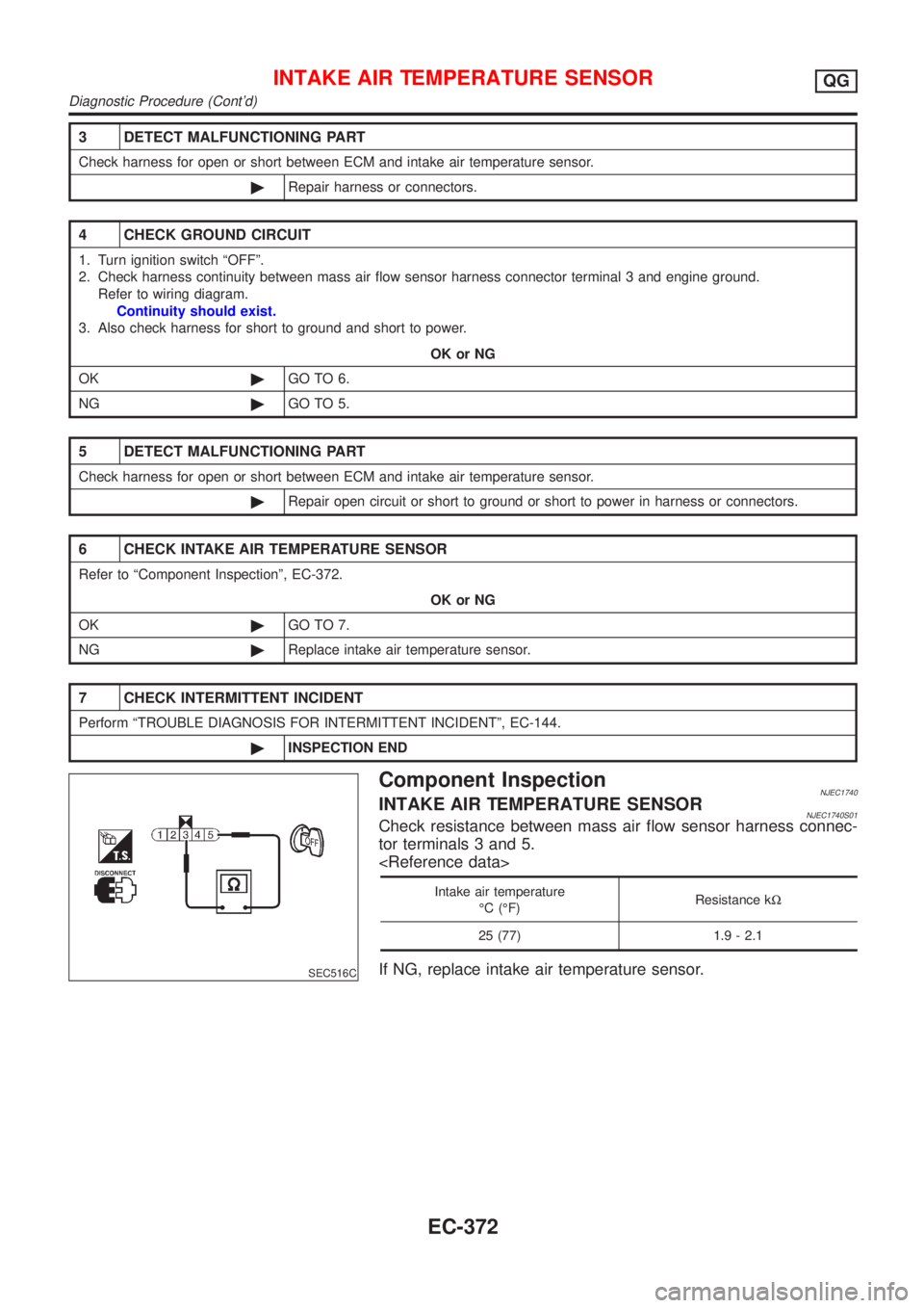
SEC516C
Component InspectionNJEC1740INTAKE AIR TEMPERATURE SENSORNJEC1740S01Check resistance between mass air flow sensor harness connec-
tor terminals 3 and 5.
Intake air temperature
ÉC (ÉF)Resistance kW
25 (77) 1.9 - 2.1
If NG, replace intake air temperature sensor.
INTAKE AIR TEMPERATURE SENSORQG
Diagnostic Procedure (Cont'd)
EC-372
Page 670 of 2493
Wiring DiagramNJEC1220
YEC986
HEATED OXYGEN SENSOR 1 (FRONT)QG
Wiring Diagram
EC-374
Page 672 of 2493
4 RETIGHTEN GROUND SCREWS
1. Turn ignition switch ªOFFº.
2. Loosen and retighten engine ground screws.
JEF104Y
3. Disconnect heated oxygen sensor 1 (front) harness connector.
SEF012XA
©GO TO 5.
5 RETIGHTEN HEATED OXYGEN SENSOR 1 (FRONT)
Loosen and retighten corresponding heated oxygen sensor 1 (front).
Tightening torque:
40 - 50 N´m (4.1 - 5.1 kg-m, 30 - 37 ft-lb)
©GO TO 6.
6 CHECK INPUT SIGNAL CIRCUIT
1. Disconnect ECM harness connector.
2. Check harness continuity between ECM terminal 62 and heated oxygen sensor 1 (front) harness connector terminal 2.
Refer to wiring diagram.
Continuity should exist.
3. Check harness continuity between ECM terminal 62 (or terminal 2) and ground.
Continuity should not exist.
4. Also check harness for short to power.
OK or NG
OK©GO TO 7.
NG©Repair open circuit or short to ground or short to power in harness or connectors.
HEATED OXYGEN SENSOR 1 (FRONT)QG
Diagnostic Procedure (Cont'd)
EC-376
Page 676 of 2493
Wiring DiagramNJEC1228
YEC987
HEATED OXYGEN SENSOR 1 HEATER (FRONT)QG
Wiring Diagram
EC-380
Page 678 of 2493

3 DETECT MALFUNCTIONING PART
Check the following.
+Harness connectors F113, M169
+10A fuse
+Harness for open or short between heated oxygen sensor 1 (front) and fuse
©Repair harness or connectors.
4 CHECK GROUND CIRCUIT
1. Turn ignition switch ªOFFº.
2. Disconnect ECM harness connector.
3. Check harness continuity between heated oxygen sensor 1 (front) harness connector terminal 3 and ECM terminal 4.
Refer to wiring diagram.
Continuity should exist.
4. Also check harness for short to ground and short to power.
OK or NG
OK©GO TO 5.
NG©Repair open circuit or short to ground or short to power in harness or connectors.
5 CHECK HEATED OXYGEN SENSOR 1 HEATER (FRONT)
Refer to ªComponent Inspectionº, EC-382.
OK or NG
OK©GO TO 6.
NG©Replace heated oxygen sensor 1 (front).
6 CHECK INTERMITTENT INCIDENT
Perform ªTROUBLE DIAGNOSIS FOR INTERMITTENT INCIDENTº, EC-144.
©INSPECTION END
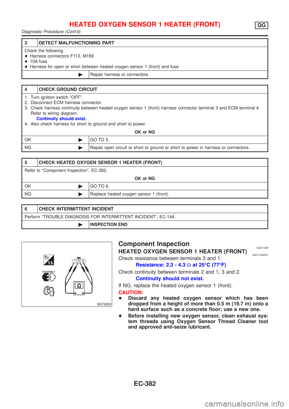
SEF935X
Component InspectionNJEC1230HEATED OXYGEN SENSOR 1 HEATER (FRONT)NJEC1230S01Check resistance between terminals 3 and 1.
Resistance: 2.3 - 4.3Wat 25ÉC (77ÉF)
Check continuity between terminals 2 and 1, 3 and 2.
Continuity should not exist.
If NG, replace the heated oxygen sensor 1 (front).
CAUTION:
+Discard any heated oxygen sensor which has been
dropped from a height of more than 0.5 m (19.7 in) onto a
hard surface such as a concrete floor; use a new one.
+Before installing new oxygen sensor, clean exhaust sys-
tem threads using Oxygen Sensor Thread Cleaner tool
and approved anti-seize lubricant.
HEATED OXYGEN SENSOR 1 HEATER (FRONT)QG
Diagnostic Procedure (Cont'd)
EC-382
Page 680 of 2493
Wiring DiagramNJEC1237
YEC988
HEATED OXYGEN SENSOR 2 (REAR)QG
Wiring Diagram
EC-384
Page 682 of 2493
3 RETIGHTEN GROUND SCREWS
1. Turn ignition switch ªOFFº.
2. Loosen and retighten engine ground screws.
JEF104Y
©GO TO 4.
4 CHECK INPUT SIGNAL CIRCUIT
1. Turn ignition switch ªOFFº.
2. Disconnect heated oxygen sensor 2 (rear) harness connector and ECM harness connector.
NEF345A
3. Check harness continuity between ECM terminal 63 and heated oxygen sensor 2 (rear) harness connector terminal 1.
Refer to wiring diagram.
Continuity should exist.
4. Check harness continuity between ECM terminal 63 [or heated oxygen sensor 2 (rear) harness connector terminal 1]
and ground.
Continuity should not exist.
5. Also check harness for short to ground and short to power.
OK or NG
OK©GO TO 6.
NG©GO TO 5.
5 DETECT MALFUNCTIONING PART
Check the harness for open or short between heated oxygen sensor 2 (rear) and ECM.
©Repair open circuit or short to ground or short to power in harness or connectors.
HEATED OXYGEN SENSOR 2 (REAR)QG
Diagnostic Procedure (Cont'd)
EC-386