Page 619 of 2493
Wiring DiagramNJEC0292
YEC052A
DTC P0510 CLOSED THROTTLE POSITION SWITCH (WHERE FITTED)QG
Wiring Diagram
EC-323
Page 620 of 2493
Diagnostic ProcedureNJEC0293
1 CHECK POWER SUPPLY
1. Turn ignition switch ªOFFº.
2. Disconnect throttle position switch harness connector.
JEF091Y
3. Turn ignition switch ªONº.
4. Check voltage between terminal 5 and engine ground with CONSULT-II or tester.
SEF837X
Voltage: Battery voltage
OK or NG
OK©GO TO 3.
NG©GO TO 2.
2 DETECT MALFUNCTIONING PART
Check the following.
+Harness connectors M169, F113
+10A fuse
+Harness for open or short between throttle position switch and fuse
©Repair harness or connectors.
3 CHECK INPUT SIGNAL CIRCUIT
1. Turn ignition switch ªOFFº.
2. Disconnect ECM harness connector.
3. Check harness continuity between ECM terminal 40 and terminal 4.
Refer to wiring diagram.
Continuity should exist.
4. Also check harness for short to ground and short to power.
OK or NG
OK©GO TO 5.
NG©GO TO 4.
DTC P0510 CLOSED THROTTLE POSITION SWITCH (WHERE FITTED)QG
Diagnostic Procedure
EC-324
Page 622 of 2493
1) Start engine and warm it up to normal operating temperature.
2) Turn ignition switch ªOFFº.
3) Disconnect throttle position switch harness connector.
4) Check continuity between terminals 4 and 5 under the follow-
ing conditions. Refer to wiring diagram.
NOTE:
Continuity measurement must be made with closed throttle
position switch installed in vehicle.
Throttle valve conditions Continuity
Completely closed Yes
Partially open or completely open No
If NG, adjust closed throttle position switch. Refer to ªBasic
Inspectionº, EC-98.
5) If it is impossible to adjust closed throttle position switch in
ªBasic Inspectionº, replace closed throttle position switch.
DTC P0510 CLOSED THROTTLE POSITION SWITCH (WHERE FITTED)QG
Component Inspection (Cont'd)
EC-326
Page 627 of 2493
Wiring DiagramNJEC0519
YEC007A
D T C P 1111INTAKE VALVE TIMING CONTROL SOLENOID VALVEQG
Wiring Diagram
EC-331
Page 628 of 2493

Diagnostic ProcedureNJEC0520
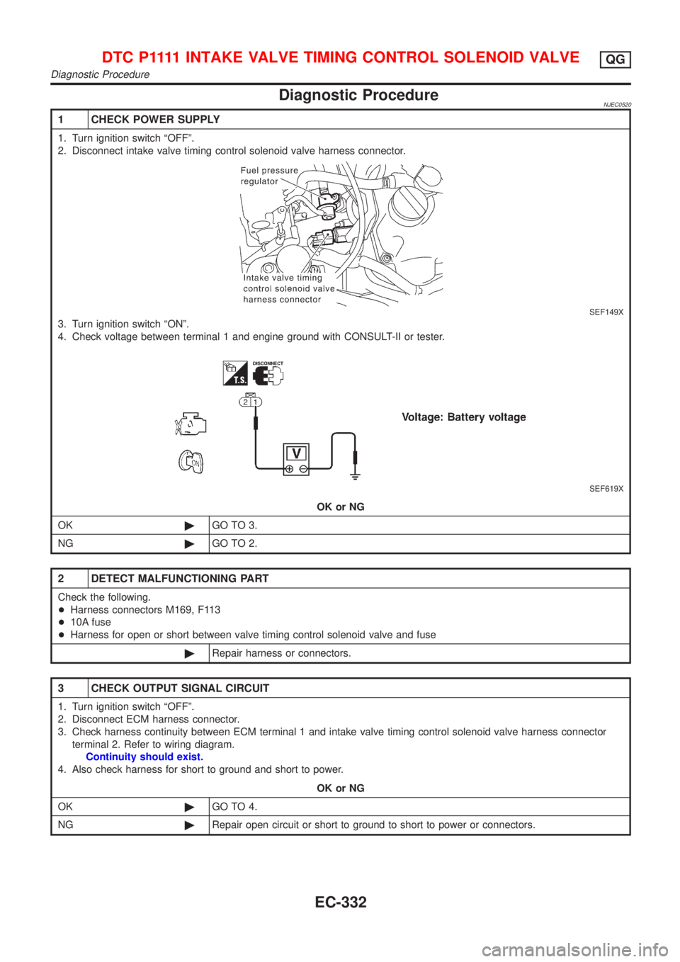
1 CHECK POWER SUPPLY
1. Turn ignition switch ªOFFº.
2. Disconnect intake valve timing control solenoid valve harness connector.
SEF149X
3. Turn ignition switch ªONº.
4. Check voltage between terminal 1 and engine ground with CONSULT-II or tester.
SEF619X
OK or NG
OK©GO TO 3.
NG©GO TO 2.
2 DETECT MALFUNCTIONING PART
Check the following.
+Harness connectors M169, F113
+10A fuse
+Harness for open or short between valve timing control solenoid valve and fuse
©Repair harness or connectors.
3 CHECK OUTPUT SIGNAL CIRCUIT
1. Turn ignition switch ªOFFº.
2. Disconnect ECM harness connector.
3. Check harness continuity between ECM terminal 1 and intake valve timing control solenoid valve harness connector
terminal 2. Refer to wiring diagram.
Continuity should exist.
4. Also check harness for short to ground and short to power.
OK or NG
OK©GO TO 4.
NG©Repair open circuit or short to ground to short to power or connectors.
D T C P 1111INTAKE VALVE TIMING CONTROL SOLENOID VALVEQG
Diagnostic Procedure
EC-332
Page 633 of 2493
Wiring DiagramNJEC0490FOR EUROPENJEC0490S03
YEC982
DTC P1217 OVERHEAT (COOLING SYSTEM)QG
Wiring Diagram
EC-337
Page 634 of 2493
FOR AUSTRALIA AND SOUTH AFRICA MODELSNJEC0490S04
YEC047A
DTC P1217 OVERHEAT (COOLING SYSTEM)QG
Wiring Diagram (Cont'd)
EC-338
Page 637 of 2493

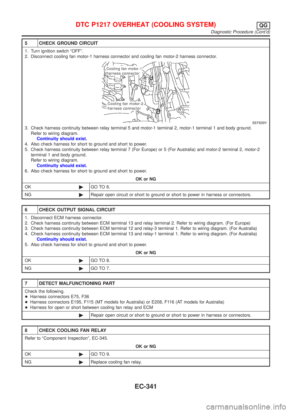
5 CHECK GROUND CIRCUIT
1. Turn ignition switch ªOFFº.
2. Disconnect cooling fan motor-1 harness connector and cooling fan motor-2 harness connector.
SEF609Y
3. Check harness continuity between relay terminal 5 and motor-1 terminal 2, motor-1 terminal 1 and body ground.
Refer to wiring diagram.
Continuity should exist.
4. Also check harness for short to ground and short to power.
5. Check harness continuity between relay terminal 7 (For Europe) or 5 (For Australia) and motor-2 terminal 2, motor-2
terminal 1 and body ground.
Refer to wiring diagram.
Continuity should exist.
6. Also check harness for short to ground and short to power.
OK or NG
OK©GO TO 6.
NG©Repair open circuit or short to ground or short to power in harness or connectors.
6 CHECK OUTPUT SIGNAL CIRCUIT
1. Disconnect ECM harness connector.
2. Check harness continuity between ECM terminal 13 and relay terminal 2. Refer to wiring diagram. (For Europe)
3. Check harness continuity between ECM terminal 12 and relay-3 terminal 1. Refer to wiring diagram. (For Australia)
4. Check harness continuity between ECM terminal 13 and relay-1 terminal 1. Refer to wiring diagram. (For Australia)
Continuity should exist.
5. Also check harness for short to ground and short to power.
OK or NG
OK©GO TO 8.
NG©GO TO 7.
7 DETECT MALFUNCTIONING PART
Check the following.
+Harness connectors E75, F36
+Harness connectors E195, F115 (MT models for Australia) or E208, F116 (AT models for Australia)
+Harness for open or short between cooling fan relay and ECM
©Repair open circuit or short to ground or short to power in harness or connectors.
8 CHECK COOLING FAN RELAY
Refer to ªComponent Inspectionº, EC-345.
OK or NG
OK©GO TO 9.
NG©Replace cooling fan relay.
DTC P1217 OVERHEAT (COOLING SYSTEM)QG
Diagnostic Procedure (Cont'd)
EC-341