Page 570 of 2493
Wiring DiagramNJEC0555
YEC973
DTC P0335 CRANKSHAFT POSITION SENSOR (POS)QG
Wiring Diagram
EC-274
Page 572 of 2493

3 DETECT MALFUNCTIONING PART
Check the following.
+Joint connector-6
+Harness connectors E75, F36
+Harness for open or short between joint connector and ECM relay
+Harness for open or short between crankshaft position sensor and joint connector
+Harness for open or short between joint connector and ECM
+ECM relay
©Repair open circuit or short to ground or short to power in harness or connectors.
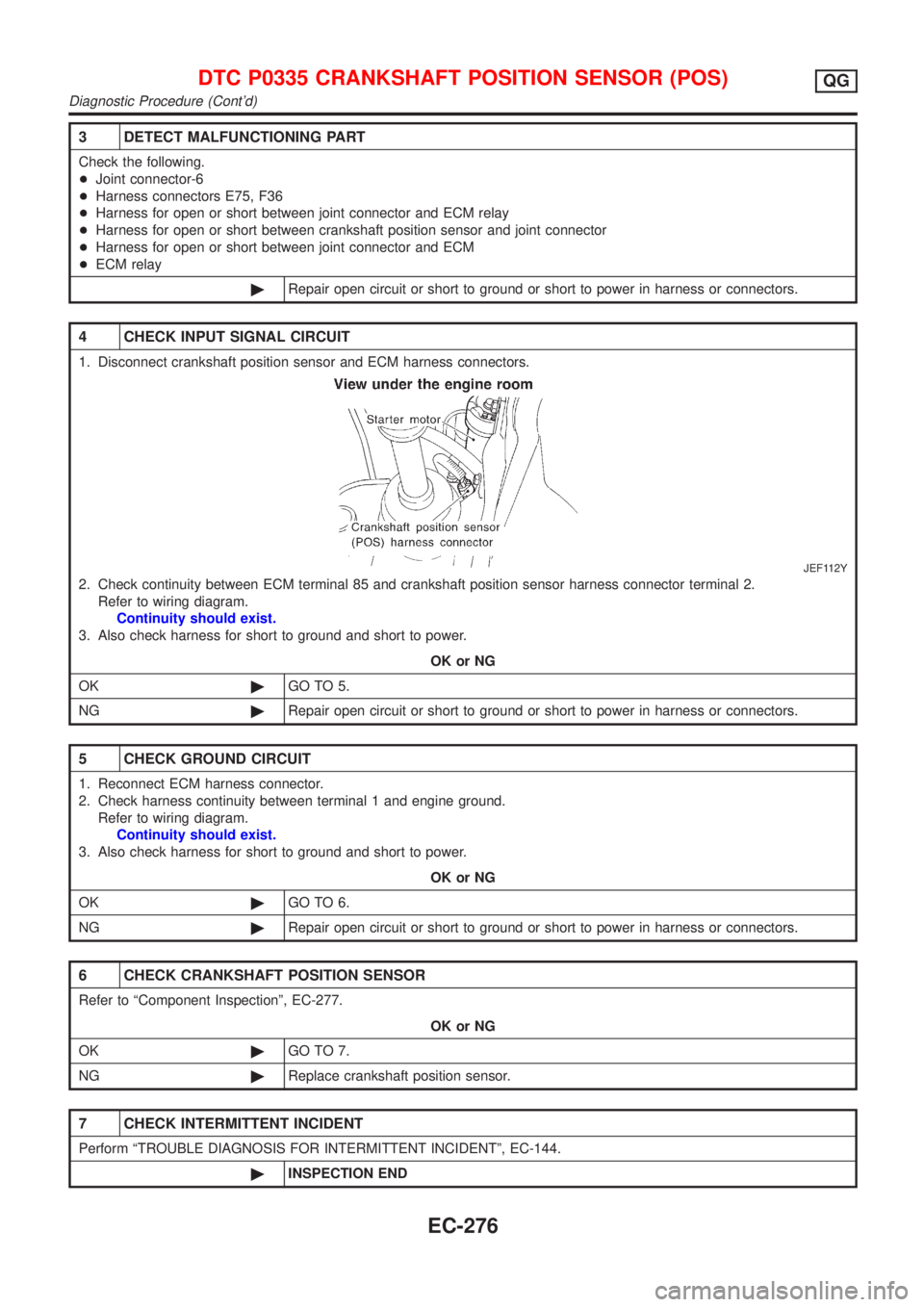
4 CHECK INPUT SIGNAL CIRCUIT
1. Disconnect crankshaft position sensor and ECM harness connectors.
JEF112Y
2. Check continuity between ECM terminal 85 and crankshaft position sensor harness connector terminal 2.
Refer to wiring diagram.
Continuity should exist.
3. Also check harness for short to ground and short to power.
OK or NG
OK©GO TO 5.
NG©Repair open circuit or short to ground or short to power in harness or connectors.
5 CHECK GROUND CIRCUIT
1. Reconnect ECM harness connector.
2. Check harness continuity between terminal 1 and engine ground.
Refer to wiring diagram.
Continuity should exist.
3. Also check harness for short to ground and short to power.
OK or NG
OK©GO TO 6.
NG©Repair open circuit or short to ground or short to power in harness or connectors.
6 CHECK CRANKSHAFT POSITION SENSOR
Refer to ªComponent Inspectionº, EC-277.
OK or NG
OK©GO TO 7.
NG©Replace crankshaft position sensor.
7 CHECK INTERMITTENT INCIDENT
Perform ªTROUBLE DIAGNOSIS FOR INTERMITTENT INCIDENTº, EC-144.
©INSPECTION END
DTC P0335 CRANKSHAFT POSITION SENSOR (POS)QG
Diagnostic Procedure (Cont'd)
EC-276
Page 576 of 2493
Wiring DiagramNJEC0224
YEC974
DTC P0340 CAMSHAFT POSITION SENSOR (CMPS) (PHASE)QG
Wiring Diagram
EC-280
Page 578 of 2493

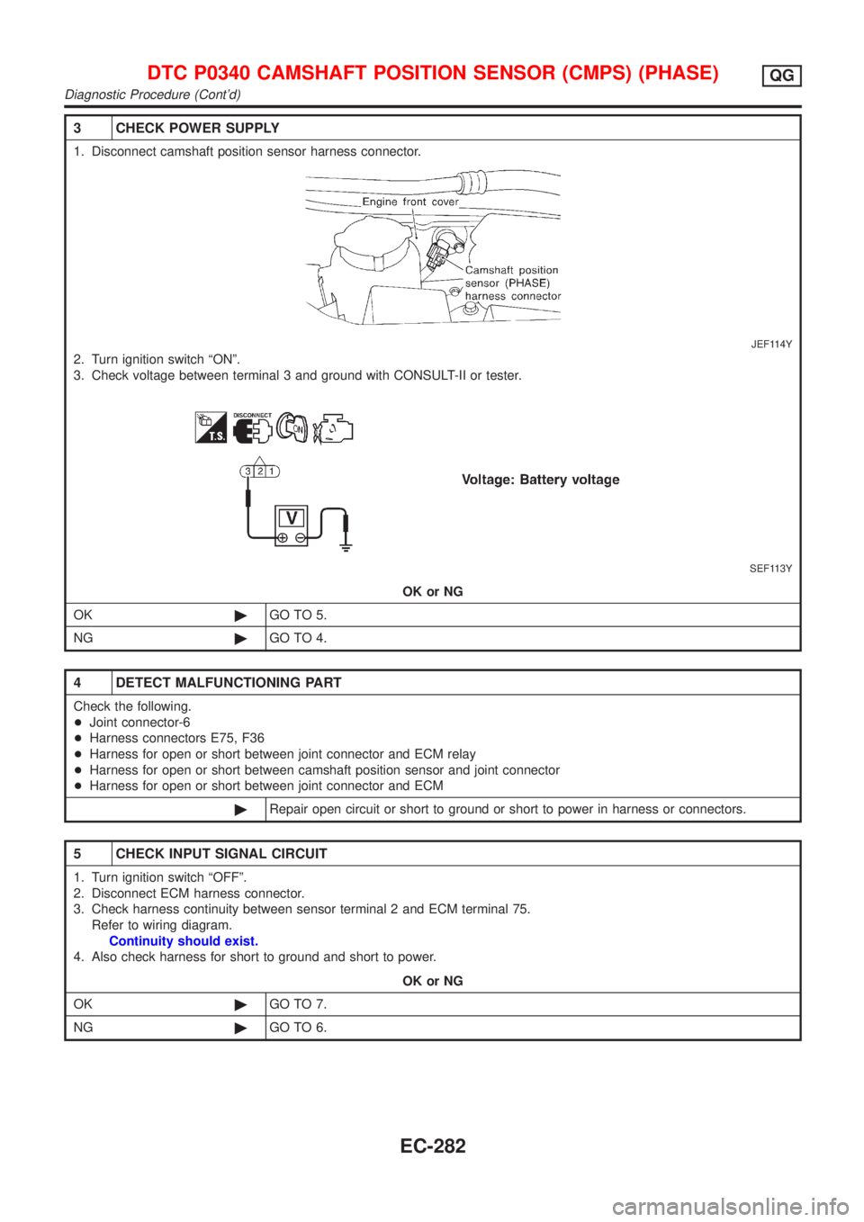
3 CHECK POWER SUPPLY
1. Disconnect camshaft position sensor harness connector.
JEF114Y
2. Turn ignition switch ªONº.
3. Check voltage between terminal 3 and ground with CONSULT-II or tester.
SEF113Y
OK or NG
OK©GO TO 5.
NG©GO TO 4.
4 DETECT MALFUNCTIONING PART
Check the following.
+Joint connector-6
+Harness connectors E75, F36
+Harness for open or short between joint connector and ECM relay
+Harness for open or short between camshaft position sensor and joint connector
+Harness for open or short between joint connector and ECM
©Repair open circuit or short to ground or short to power in harness or connectors.
5 CHECK INPUT SIGNAL CIRCUIT
1. Turn ignition switch ªOFFº.
2. Disconnect ECM harness connector.
3. Check harness continuity between sensor terminal 2 and ECM terminal 75.
Refer to wiring diagram.
Continuity should exist.
4. Also check harness for short to ground and short to power.
OK or NG
OK©GO TO 7.
NG©GO TO 6.
DTC P0340 CAMSHAFT POSITION SENSOR (CMPS) (PHASE)QG
Diagnostic Procedure (Cont'd)
EC-282
Page 579 of 2493
6 DETECT MALFUNCTIONING PART
Check the following.
+Harness for open or short between ECM and joint connector
+Harness for open or short between joint connector and camshaft position sensor
©Repair open circuit or short to ground or short to power in harness or connectors.
7 CHECK GROUND CIRCUIT
1. Turn ignition switch ªOFFº.
2. Check harness continuity between sensor terminal 1 and engine ground.
Refer to wiring diagram.
Continuity should exist.
3. Also check harness for short to ground and short to power.
OK or NG
OK©GO TO 8.
NG©Repair open circuit or short to ground or short to power in harness or connectors.
8 CHECK CAMSHAFT POSITION SENSOR
Refer to ªComponent Inspectionº, EC-284.
OK or NG
OK©GO TO 9.
NG©Replace camshaft position sensor.
9 CHECK INTERMITTENT INCIDENT
Perform ªTROUBLE DIAGNOSIS FOR INTERMITTENT INCIDENTº, EC-144.
©INSPECTION END
DTC P0340 CAMSHAFT POSITION SENSOR (CMPS) (PHASE)QG
Diagnostic Procedure (Cont'd)
EC-283
Page 585 of 2493
Wiring DiagramNJEC0231
YEC975
DTC P0400 EGR FUNCTION (CLOSED) (WHERE FITTED)QG
Wiring Diagram
EC-289
Page 587 of 2493

4 CHECK OUTPUT SIGNAL CIRCUIT
1. Turn ignition switch ªOFFº.
2. Disconnect ECM harness connector.
3. Check harness continuity between
ECM terminal 8 and terminal 1,
ECM terminal 9 and terminal 4,
ECM terminal 17 and terminal 3,
ECM terminal 18 and terminal 6.
Refer to wiring diagram.
Continuity should exist.
If OK, check harness for short to ground and short to power.
OK or NG
OK©GO TO 5.
NG©Repair open circuit, short to ground or short to power in harness connectors.
5 CHECK EGR PASSAGE
Check EGR passage for clogging and cracks.
OK or NG
OK©GO TO 6.
NG©Repair or replace EGR passage.
6 CHECK EGR TEMPERATURE SENSOR
Refer to ªCOMPONENT INSPECTIONº, EC-352.
OK or NG
OK©GO TO 7.
NG©Replace EGR temperature sensor.
7 CHECK EGR VOLUME CONTROL VALVE
Refer to ªCOMPONENT INSPECTIONº, EC-292.
OK or NG
OK©GO TO 8.
NG©Replace EGR volume control valve.
8 CHECK INTERMITTENT INCIDENT
Perform ªTROUBLE DIAGNOSIS FOR INTERMITTENT INCIDENTº, EC-144.
©INSPECTION END
DTC P0400 EGR FUNCTION (CLOSED) (WHERE FITTED)QG
Diagnostic Procedure (Cont'd)
EC-291
Page 592 of 2493
Wiring DiagramNJEC0510
YEC976
DTC P0403 EGR VOLUME CONTROL VALVE (CIRCUIT)
(WHERE FITTED)
QG
Wiring Diagram
EC-296