Page 457 of 2493

Diagnostic ProcedureNJEC0070
1 CHECK POWER SUPPLY (Models with intake air temperature sensor in mass air flow sensor)
1. Turn ignition switch ªOFFº.
2. Disconnect mass air flow sensor harness connector.
JEF105Y
3. Turn ignition switch ªONº.
4. Check voltage between terminal 5 and ground with CONSULT-II or tester.
SEC503C
OK or NG
OK©GO TO 3.
NG©GO TO 2.
2 DETECT MALFUNCTIONING PART
Check the following.
+Harness for open or short between ECM and intake air temperature sensor
©Repair harness or connectors.
3 CHECK GROUND CIRCUIT
1. Turn ignition switch ªOFFº.
2. Check harness continuity between intake air temperature sensor harness connector terminal 2 and engine ground.
Refer to wiring diagram.
Continuity should exist.
3. Also check harness for short to ground and short to power.
OK or NG
OK©GO TO 5.
NG©GO TO 4.
4 DETECT MALFUNCTIONING PART
Check the following.
+Harness for open or short between ECM and intake air temperature sensor
©Repair open circuit or short to ground or short to power in harness or connectors.
DTC P0110 INTAKE AIR TEMPERATURE SENSORQG
Diagnostic Procedure
EC-161
Page 461 of 2493
Wiring DiagramNJEC0076
YEC965
DTC P0115 ENGINE COOLANT TEMPERATURE SENSOR (ECTS)
(CIRCUIT)
QG
Wiring Diagram
EC-165
Page 462 of 2493
Diagnostic ProcedureNJEC0077
1 CHECK POWER SUPPLY
1. Turn ignition switch ªOFFº.
2. Disconnect engine coolant temperature sensor harness connector.
SEF999W
3. Turn ignition switch ªONº.
4. Check voltage between terminal 1 and ground with CONSULT-II or tester.
SEF301X
OK or NG
OK©GO TO 3.
NG©GO TO 2.
2 DETECT MALFUNCTIONING PART
Check the harness for open or short between ECM and engine coolant temperature sensor.
©Repair harness or connectors.
3 CHECK GROUND CIRCUIT
1. Turn ignition switch ªOFFº.
2. Check harness continuity between engine coolant temperature sensor harness connector terminal 2 and engine
ground.
Refer to wiring diagram.
Continuity should exist.
3. Also check harness for short to ground and short to power.
OK or NG
OK©GO TO 5.
NG©GO TO 4.
DTC P0115 ENGINE COOLANT TEMPERATURE SENSOR (ECTS)
(CIRCUIT)
QG
Diagnostic Procedure
EC-166
Page 467 of 2493
Wiring DiagramNJEC0084
YEC966
DTC P0120 THROTTLE POSITION SENSORQG
Wiring Diagram
EC-171
Page 469 of 2493

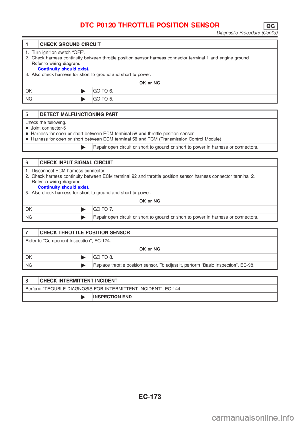
4 CHECK GROUND CIRCUIT
1. Turn ignition switch ªOFFº.
2. Check harness continuity between throttle position sensor harness connector terminal 1 and engine ground.
Refer to wiring diagram.
Continuity should exist.
3. Also check harness for short to ground and short to power.
OK or NG
OK©GO TO 6.
NG©GO TO 5.
5 DETECT MALFUNCTIONING PART
Check the following.
+Joint connector-6
+Harness for open or short between ECM terminal 58 and throttle position sensor
+Harness for open or short between ECM terminal 58 and TCM (Transmission Control Module)
©Repair open circuit or short to ground or short to power in harness or connectors.
6 CHECK INPUT SIGNAL CIRCUIT
1. Disconnect ECM harness connector.
2. Check harness continuity between ECM terminal 92 and throttle position sensor harness connector terminal 2.
Refer to wiring diagram.
Continuity should exist.
3. Also check harness for short to ground and short to power.
OK or NG
OK©GO TO 7.
NG©Repair open circuit or short to ground or short to power in harness or connectors.
7 CHECK THROTTLE POSITION SENSOR
Refer to ªComponent Inspectionº, EC-174.
OK or NG
OK©GO TO 8.
NG©Replace throttle position sensor. To adjust it, perform ªBasic Inspectionº, EC-98.
8 CHECK INTERMITTENT INCIDENT
Perform ªTROUBLE DIAGNOSIS FOR INTERMITTENT INCIDENTº, EC-144.
©INSPECTION END
DTC P0120 THROTTLE POSITION SENSORQG
Diagnostic Procedure (Cont'd)
EC-173
Page 475 of 2493
Wiring DiagramNJEC0100
YEC967
DTC P0130 HEATED OXYGEN SENSOR 1 (FRONT) (CIRCUIT)QG
Wiring Diagram
EC-179
Page 476 of 2493

Diagnostic ProcedureNJEC0101
1 INSPECTION START
1. Turn ignition switch ªOFFº.
2. Loosen and retighten engine ground screws.
JEF104Y
3. Disconnect heated oxygen sensor 1 (front) harness connector.
SEF012XA
©GO TO 2.
2 CHECK INPUT SIGNAL CIRCUIT
1. Disconnect ECM harness connector.
2. Check harness continuity between ECM terminal 62 and heated oxygen sensor 1 (front) harness connector terminal 2.
Refer to wiring diagram.
Continuity should exist.
3. Check harness continuity between ECM terminal 62 (or terminal 2) and ground.
Continuity should not exist.
4. Also check harness for short to power.
OK or NG
OK©GO TO 3.
NG©Repair open circuit or short to ground or short to power in harness or connectors.
3 CHECK HEATED OXYGEN SENSOR 1 (FRONT)
Refer to ªComponent Inspectionº, EC-181.
OK or NG
OK©GO TO 4.
NG©Replace heated oxygen sensor 1 (front).
4 CHECK INTERMITTENT INCIDENT
Perform ªTROUBLE DIAGNOSIS FOR INTERMITTENT INCIDENTº, EC-144.
©INSPECTION END
DTC P0130 HEATED OXYGEN SENSOR 1 (FRONT) (CIRCUIT)QG
Diagnostic Procedure
EC-180
Page 482 of 2493

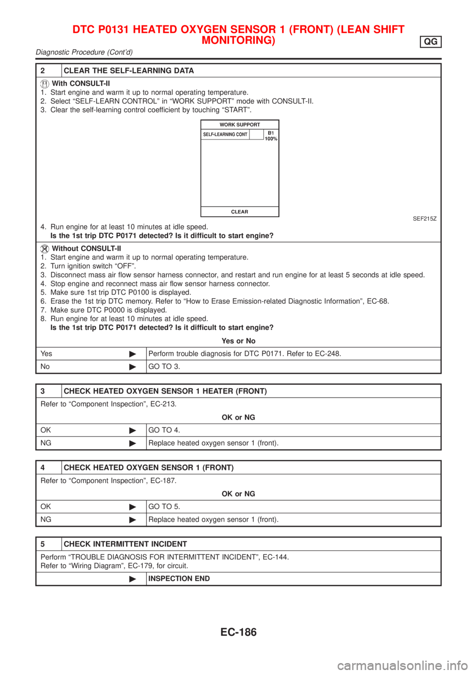
2 CLEAR THE SELF-LEARNING DATA
With CONSULT-II
1. Start engine and warm it up to normal operating temperature.
2. Select ªSELF-LEARN CONTROLº in ªWORK SUPPORTº mode with CONSULT-II.
3. Clear the self-learning control coefficient by touching ªSTARTº.
SEF215Z
4. Run engine for at least 10 minutes at idle speed.
Is the 1st trip DTC P0171 detected? Is it difficult to start engine?
Without CONSULT-II
1. Start engine and warm it up to normal operating temperature.
2. Turn ignition switch ªOFFº.
3. Disconnect mass air flow sensor harness connector, and restart and run engine for at least 5 seconds at idle speed.
4. Stop engine and reconnect mass air flow sensor harness connector.
5. Make sure 1st trip DTC P0100 is displayed.
6. Erase the 1st trip DTC memory. Refer to ªHow to Erase Emission-related Diagnostic Informationº, EC-68.
7. Make sure DTC P0000 is displayed.
8. Run engine for at least 10 minutes at idle speed.
Is the 1st trip DTC P0171 detected? Is it difficult to start engine?
YesorNo
Ye s©Perform trouble diagnosis for DTC P0171. Refer to EC-248.
No©GO TO 3.
3 CHECK HEATED OXYGEN SENSOR 1 HEATER (FRONT)
Refer to ªComponent Inspectionº, EC-213.
OK or NG
OK©GO TO 4.
NG©Replace heated oxygen sensor 1 (front).
4 CHECK HEATED OXYGEN SENSOR 1 (FRONT)
Refer to ªComponent Inspectionº, EC-187.
OK or NG
OK©GO TO 5.
NG©Replace heated oxygen sensor 1 (front).
5 CHECK INTERMITTENT INCIDENT
Perform ªTROUBLE DIAGNOSIS FOR INTERMITTENT INCIDENTº, EC-144.
Refer to ªWiring Diagramº, EC-179, for circuit.
©INSPECTION END
DTC P0131 HEATED OXYGEN SENSOR 1 (FRONT) (LEAN SHIFT
MONITORING)
QG
Diagnostic Procedure (Cont'd)
EC-186