Page 1728 of 2493
SBR574
AssemblyNJBR00341. Insert piston seal into groove on cylinder body.
2. With piston boot fitted to piston, insert piston boot into groove
on cylinder body and install piston.
3. Properly secure piston boot.
SBR980B
InstallationNJBR0035CAUTION:
+Refill with new brake fluid ªDOT 4º.
+Never reuse drained brake fluid.
1. Install brake hose to caliper securely.
2. Install all parts and secure all bolts.
3. Bleed air. Refer to ªBleeding Brake Systemº, BR-8.
FRONT DISC BRAKE
Assembly
BR-30
Page 1737 of 2493
Pin and Pin BootNJBR0041S0104Check for wear, cracks or other damage.
Replace if any of the above conditions are observed.
SBR219C
ROTORNJBR0041S02Rubbing SurfaceNJBR0041S0201Check rotor for roughness, cracks or chips.
RunoutNJBR0041S02021. Secure rotor to wheel hub with two nuts (M12 x 1.25).
2. Check runout using a dial indicator.
Make sure that axial end play is within the specifications
before measuring. Refer to AX section (ªREAR WHEEL
BEARINGº, ªOn-vehicle Serviceº).
3. Change relative positions of rotor and wheel hub so that runout
is minimized.
Maximum runout:
0.07 mm (0.0028 in)
ThicknessNJBR0041S0203Rotor repair limit:
Standard thickness
10 mm (0.39 in)
Minimum thickness
9 mm (0.35 in)
Thickness variation (At least 8 portions)
Maximum 0.02 mm (0.0008 in)
SBR247B
AssemblyNJBR00421. Insert cam with depression facing towards open end of cylin-
der.
REAR DISC BRAKE (CAM & STRUT TYPE)
Inspection (Cont'd)
BR-39
Page 1740 of 2493
SBR307E
InstallationNJBR0043CAUTION:
+Refill with new brake fluid ªDOT 4º.
+Never reuse drained brake fluid.
1. Install caliper assembly.
+As shown in the figure, align the piston's concave to the pad's
convex, then install the cylinder body to the torque member.
2. Install brake hose to caliper securely.
3. Install all parts and secure all bolts.
4. Bleed air. Refer to ªBleeding Brake Systemº, BR-8.
REAR DISC BRAKE (CAM & STRUT TYPE)
Installation
BR-42
Page 1744 of 2493

SBR219C
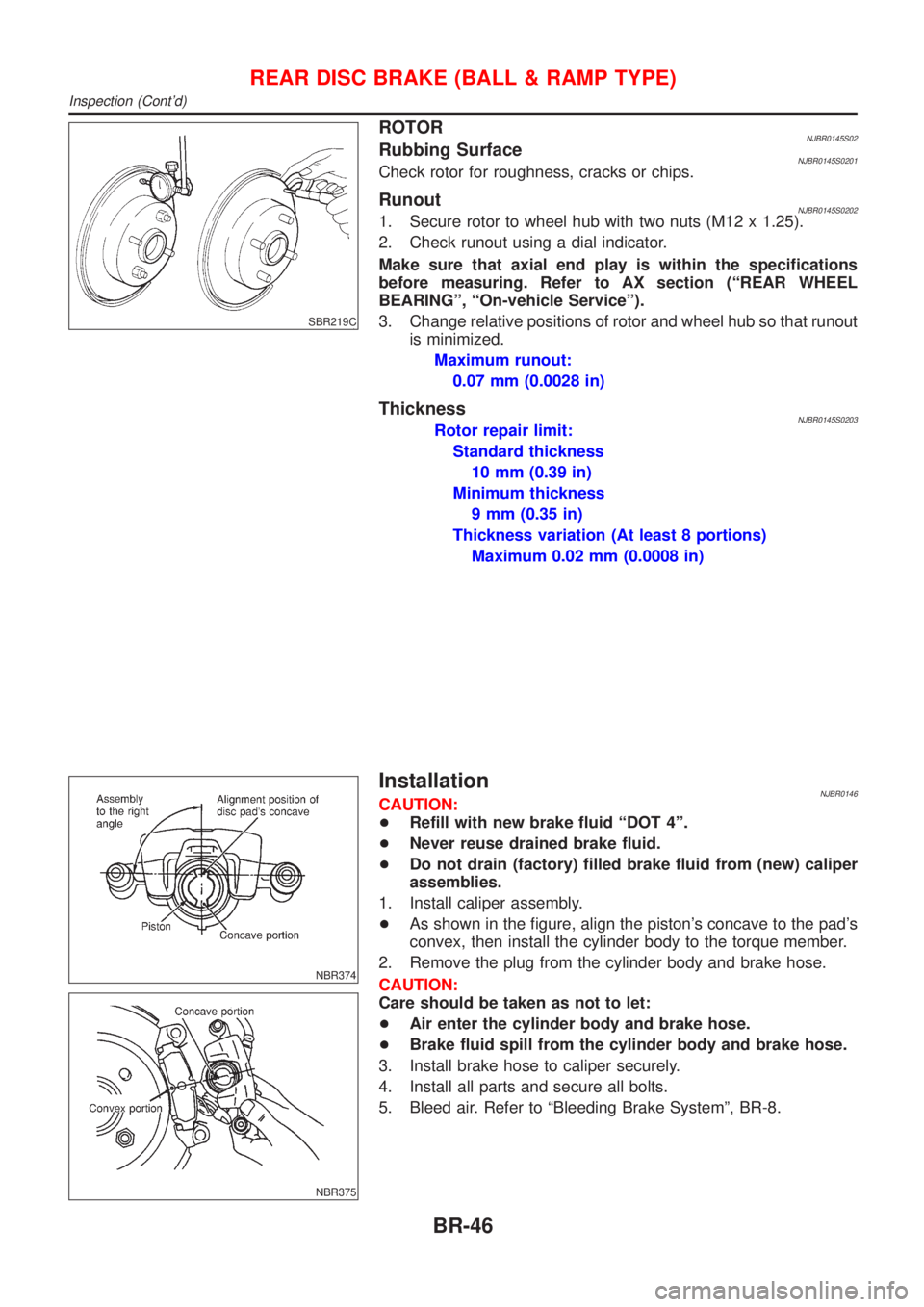
ROTORNJBR0145S02Rubbing SurfaceNJBR0145S0201Check rotor for roughness, cracks or chips.
RunoutNJBR0145S02021. Secure rotor to wheel hub with two nuts (M12 x 1.25).
2. Check runout using a dial indicator.
Make sure that axial end play is within the specifications
before measuring. Refer to AX section (ªREAR WHEEL
BEARINGº, ªOn-vehicle Serviceº).
3. Change relative positions of rotor and wheel hub so that runout
is minimized.
Maximum runout:
0.07 mm (0.0028 in)
ThicknessNJBR0145S0203Rotor repair limit:
Standard thickness
10 mm (0.39 in)
Minimum thickness
9 mm (0.35 in)
Thickness variation (At least 8 portions)
Maximum 0.02 mm (0.0008 in)
NBR374
NBR375
InstallationNJBR0146CAUTION:
+Refill with new brake fluid ªDOT 4º.
+Never reuse drained brake fluid.
+Do not drain (factory) filled brake fluid from (new) caliper
assemblies.
1. Install caliper assembly.
+As shown in the figure, align the piston's concave to the pad's
convex, then install the cylinder body to the torque member.
2. Remove the plug from the cylinder body and brake hose.
CAUTION:
Care should be taken as not to let:
+Air enter the cylinder body and brake hose.
+Brake fluid spill from the cylinder body and brake hose.
3. Install brake hose to caliper securely.
4. Install all parts and secure all bolts.
5. Bleed air. Refer to ªBleeding Brake Systemº, BR-8.
REAR DISC BRAKE (BALL & RAMP TYPE)
Inspection (Cont'd)
BR-46
Page 1745 of 2493
ComponentsNJBR0044
NBR356
SBR897D
Removal and InstallationNJBR00451. To remove parking brake cable, first remove center console.
2. Disconnect warning lamp switch connector.
3. Remove adjusting nut.
4. Remove bolts and nuts securing parking brake cable.
5. Remove parking brake device.
SBR025D
6. Remove lock plate and disconnect cable (disc brake only).
For drum brake models, refer to ‘‘Removal’’, ‘‘REAR DRUM
BRAKE’’, BR-31.
InspectionNJBR00461. Check control lever for wear or other damage. Replace if nec-
essary.
2. Check wires for discontinuity or deterioration. Replace if nec-
essary.
3. Check warning lamp and switch. Replace if necessary.
4. Check parts at each connecting portion and, if found deformed
or damaged, replace.
PARKING BRAKE CONTROL
Components
BR-47
Page 1756 of 2493

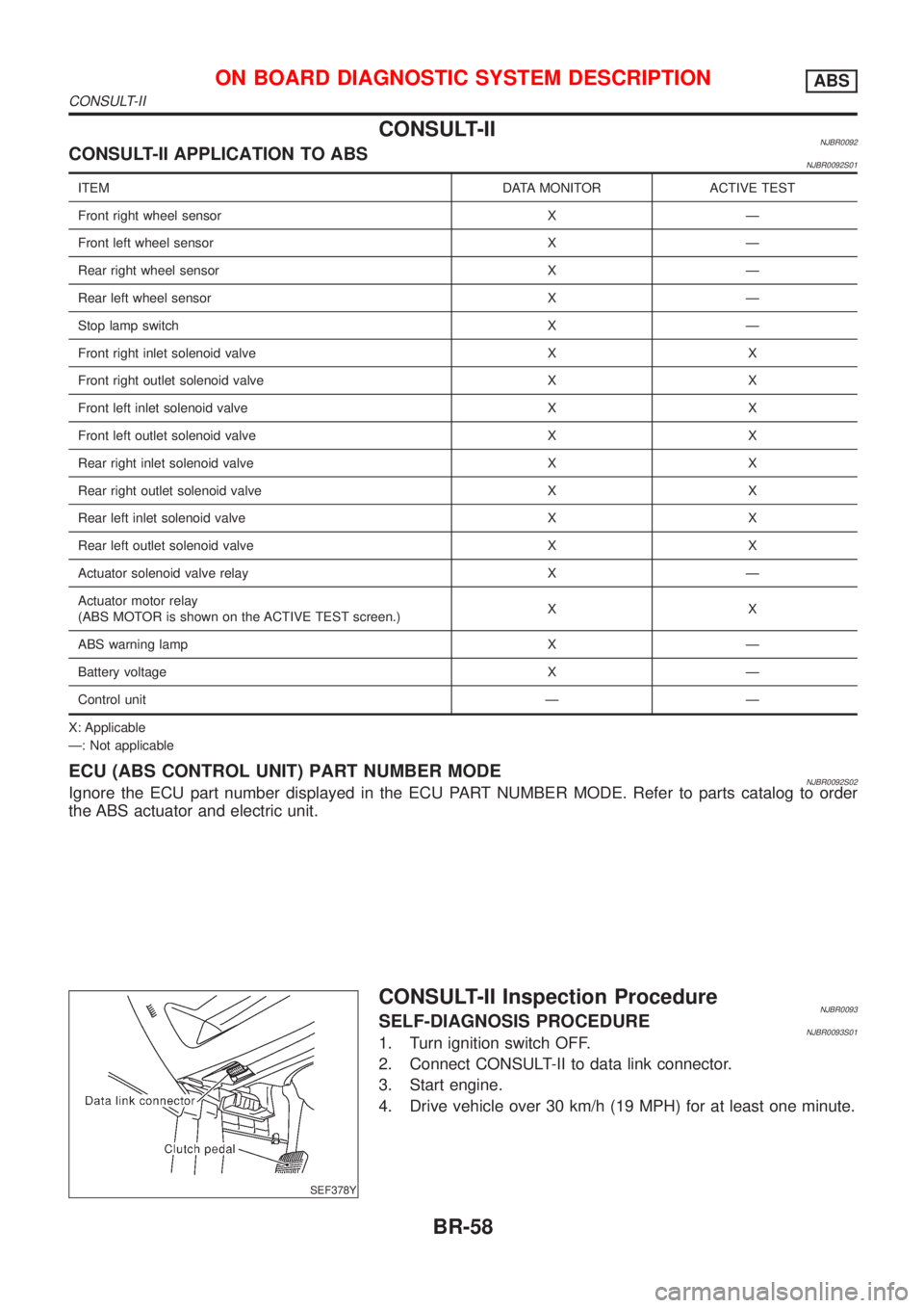
CONSULT-IINJBR0092CONSULT-II APPLICATION TO ABSNJBR0092S01
ITEM DATA MONITOR ACTIVE TEST
Front right wheel sensor X Ð
Front left wheel sensor X Ð
Rear right wheel sensor X Ð
Rear left wheel sensor X Ð
Stop lamp switch X Ð
Front right inlet solenoid valve X X
Front right outlet solenoid valve X X
Front left inlet solenoid valve X X
Front left outlet solenoid valve X X
Rear right inlet solenoid valve X X
Rear right outlet solenoid valve X X
Rear left inlet solenoid valve X X
Rear left outlet solenoid valve X X
Actuator solenoid valve relay X Ð
Actuator motor relay
(ABS MOTOR is shown on the ACTIVE TEST screen.)XX
ABS warning lamp X Ð
Battery voltage X Ð
Control unit Ð Ð
X: Applicable
Ð: Not applicable
ECU (ABS CONTROL UNIT) PART NUMBER MODENJBR0092S02Ignore the ECU part number displayed in the ECU PART NUMBER MODE. Refer to parts catalog to order
the ABS actuator and electric unit.
SEF378Y
CONSULT-II Inspection ProcedureNJBR0093SELF-DIAGNOSIS PROCEDURENJBR0093S011. Turn ignition switch OFF.
2. Connect CONSULT-II to data link connector.
3. Start engine.
4. Drive vehicle over 30 km/h (19 MPH) for at least one minute.
ON BOARD DIAGNOSTIC SYSTEM DESCRIPTIONABS
CONSULT-II
BR-58
Page 1801 of 2493

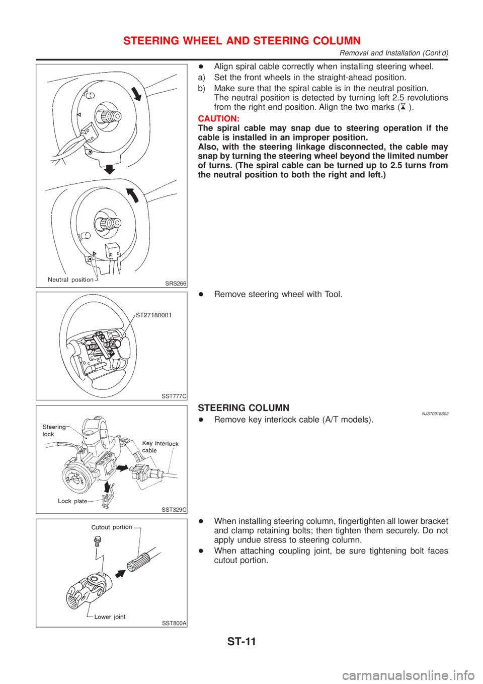
SRS266
+Align spiral cable correctly when installing steering wheel.
a) Set the front wheels in the straight-ahead position.
b) Make sure that the spiral cable is in the neutral position.
The neutral position is detected by turning left 2.5 revolutions
from the right end position. Align the two marks (
).
CAUTION:
The spiral cable may snap due to steering operation if the
cable is installed in an improper position.
Also, with the steering linkage disconnected, the cable may
snap by turning the steering wheel beyond the limited number
of turns. (The spiral cable can be turned up to 2.5 turns from
the neutral position to both the right and left.)
SST777C
+Remove steering wheel with Tool.
SST329C
STEERING COLUMNNJST0018S02+Remove key interlock cable (A/T models).
SST800A
+When installing steering column, fingertighten all lower bracket
and clamp retaining bolts; then tighten them securely. Do not
apply undue stress to steering column.
+When attaching coupling joint, be sure tightening bolt faces
cutout portion.
STEERING WHEEL AND STEERING COLUMN
Removal and Installation (Cont'd)
ST-11
Page 1809 of 2493

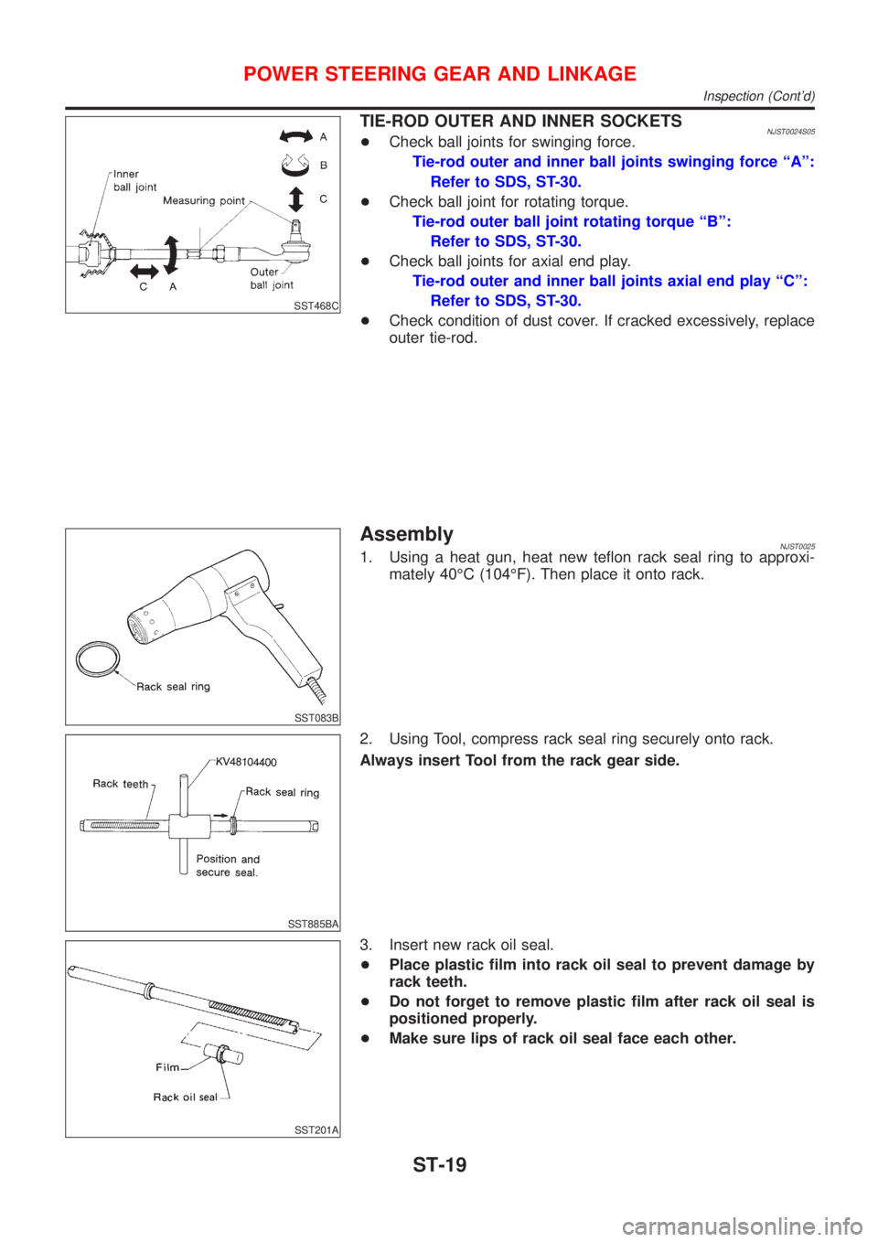
SST468C
TIE-ROD OUTER AND INNER SOCKETSNJST0024S05+Check ball joints for swinging force.
Tie-rod outer and inner ball joints swinging force ªAº:
Refer to SDS, ST-30.
+Check ball joint for rotating torque.
Tie-rod outer ball joint rotating torque ªBº:
Refer to SDS, ST-30.
+Check ball joints for axial end play.
Tie-rod outer and inner ball joints axial end play ªCº:
Refer to SDS, ST-30.
+Check condition of dust cover. If cracked excessively, replace
outer tie-rod.
SST083B
AssemblyNJST00251. Using a heat gun, heat new teflon rack seal ring to approxi-
mately 40ÉC (104ÉF). Then place it onto rack.
SST885BA
2. Using Tool, compress rack seal ring securely onto rack.
Always insert Tool from the rack gear side.
SST201A
3. Insert new rack oil seal.
+Place plastic film into rack oil seal to prevent damage by
rack teeth.
+Do not forget to remove plastic film after rack oil seal is
positioned properly.
+Make sure lips of rack oil seal face each other.
POWER STEERING GEAR AND LINKAGE
Inspection (Cont'd)
ST-19