Page 1892 of 2493
Part SRS is activated SRS is NOT activated
Harness and Connec-
tors1. Check connectors for poor connection, damage, and terminals for deformities.
2. Check harness for binding, chafing, cuts, or deformities.
3. If no damage is found, reinstall the harness and connectors.
4. DamagedÐREPLACE damaged section of harness. Do not attempt to repair, splice or modify any SRS
harness.
Instrument panel 1. When passenger air bag inflates, check the following points for bending, deformities or cracks.
+Opening portion for front passenger air bag
SRS837
+Front passenger air bag module brackets
SRS838
+The portions securing the instrument panel
SRS839
2. If no damage is found, reinstall the instrument panel.
3. If damagedÐREPLACE the instrument panel with bolts.
SUPPLEMENTAL RESTRAINT SYSTEM (SRS)
Collision Diagnosis (Cont'd)
RS-72
Page 1901 of 2493

Removal and InstallationNJBT0004+When removing or installing hood, place a cloth or other padding on hood. This prevents vehicle body from
being scratched.
+Bumper fascia is made of plastic. Do not use excessive force and be sure to keep oil away from it.
+Hood adjustment: Adjust at hinge portion.
+Hood lock adjustment: After adjusting, check hood lock control operation. Apply a coat of grease to hood
locks engaging mechanism.
+Hood opener: Do not attempt to bend cable forcibly. Doing so increases effort required to unlock hood.
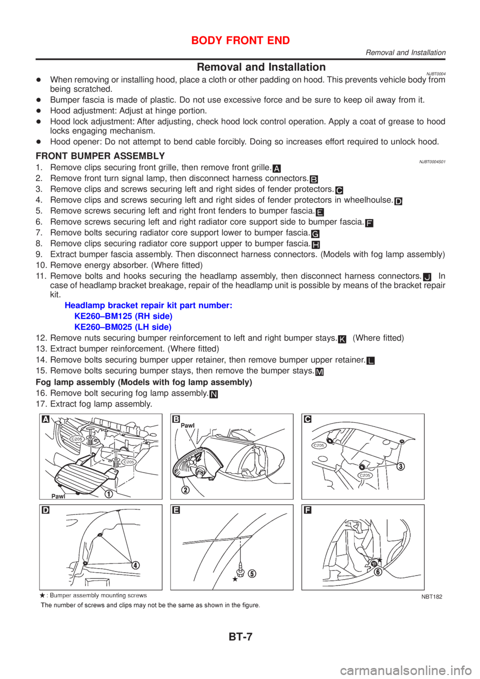
FRONT BUMPER ASSEMBLYNJBT0004S011. Remove clips securing front grille, then remove front grille.
2. Remove front turn signal lamp, then disconnect harness connectors.
3. Remove clips and screws securing left and right sides of fender protectors.
4. Remove clips and screws securing left and right sides of fender protectors in wheelhoulse.
5. Remove screws securing left and right front fenders to bumper fascia.
6. Remove screws securing left and right radiator core support side to bumper fascia.
7. Remove bolts securing radiator core support lower to bumper fascia.
8. Remove clips securing radiator core support upper to bumper fascia.
9. Extract bumper fascia assembly. Then disconnect harness connectors. (Models with fog lamp assembly)
10. Remove energy absorber. (Where fitted)
11. Remove bolts and hooks securing the headlamp assembly, then disconnect harness connectors.
In
case of headlamp bracket breakage, repair of the headlamp unit is possible by means of the bracket repair
kit.
Headlamp bracket repair kit part number:
KE260±BM125 (RH side)
KE260±BM025 (LH side)
12. Remove nuts securing bumper reinforcement to left and right bumper stays.
(Where fitted)
13. Extract bumper reinforcement. (Where fitted)
14. Remove bolts securing bumper upper retainer, then remove bumper upper retainer.
15. Remove bolts securing bumper stays, then remove the bumper stays.
Fog lamp assembly (Models with fog lamp assembly)
16. Remove bolt securing fog lamp assembly.
17. Extract fog lamp assembly.
NBT182
BODY FRONT END
Removal and Installation
BT-7
Page 1904 of 2493

Removal and Installation (Sedan)NJBT0005+When removing or installing trunk lid, place a cloth or other padding on trunk lid. This prevents vehicle
body from being scratched.
+Bumper fascia is made of plastic. Do not use excessive force and be sure to keep oil away from it.
+Trunk lid adjustment: Adjust at hinge-trunk lid portion for proper trunk lid fit.
+Trunk lid lock system adjustment: Adjust striker so that it is in the center of the lock. After adjustment, check
trunk lid lock operation.
+After installation, make sure that trunk lid and fuel filler lid open smoothly.
HFor Wiring Diagram, refer to EL, ªTRUNK LID OPENERº.
REAR BUMPER ASSEMBLYNJBT0005S011. Remove clips and screws securing left and right chipping protectors.
2. Remove screws securing left and right rear fenders to bumper fascia.
3. Remove bolts securing bumper fascia assembly.
4. Remove clips securing bumper fascia assembly.
5. Open the bumper fascia side outward to disengage from side clips.
6. Extract bumper fascia assembly.
7. Remove bolts securing bumper stays, then remove the bumper stays.
BODY REAR END AND OPENER
Removal and Installation (Sedan)
BT-10
Page 1907 of 2493

Removal and Installation (Hatchback)NJBT0034+When removing or installing back door, place a cloth or other padding on back door. This prevents vehicle
body from being scratched.
+Bumper fascia is made of plastic. Do not use excessive force and be sure to keep oil away from it.
+Back door adjustment: Adjust at hinge-back door portion for proper back door fit.
+Back door lock system adjustment: Adjust striker so that it is in the center of the lock. After adjustment,
check back door lock operation.
+After installation, make sure that back door and fuel filler lid open smoothly.
HFor Wiring Diagram, refer to EL, ªTRUNK LID OPENERº.
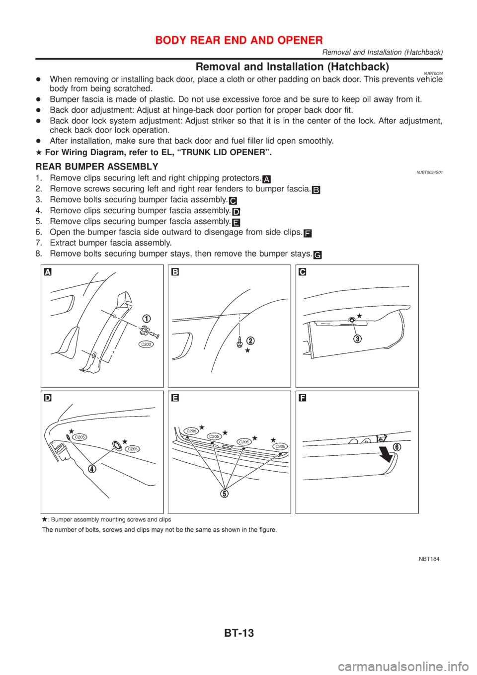
REAR BUMPER ASSEMBLYNJBT0034S011. Remove clips securing left and right chipping protectors.
2. Remove screws securing left and right rear fenders to bumper fascia.
3. Remove bolts securing bumper facia assembly.
4. Remove clips securing bumper fascia assembly.
5. Remove clips securing bumper fascia assembly.
6. Open the bumper fascia side outward to disengage from side clips.
7. Extract bumper fascia assembly.
8. Remove bolts securing bumper stays, then remove the bumper stays.
NBT184
BODY REAR END AND OPENER
Removal and Installation (Hatchback)
BT-13
Page 1911 of 2493
Front Door Glass=NJBT0007+Make sure that door glass is positioned in glass run groove.
+Make sure that there is no abnormality when door glass is
raised or lowered.
FRONT DOOR GLASS AND REGULATORNJBT0007S01
SBT236A
+For removal of front door finisher, refer to ªDOOR TRIMº,
BT-39.
+Remove sealing screen.
SBT964
1. Using power window main switch, raise or lower door glass
until carrier plate securing bolts are visible.
2. Remove bolts securing carrier plate.
DOOR
Front Door Glass
BT-17
Page 1912 of 2493
SBT965
3. Hold door glass with both hands. While raising rear end of door
glass, remove door glass from sash and away from outside the
door.
SBT966
4. Disconnect regulator assembly connector.
5. Remove bolts securing regulator assembly and guide rail, then
remove regulator assembly and guide rail.
SBT967
InspectionNJBT0007S0101Check regulator assembly for the following parts. Replace faulty
parts with new ones.
+Wire for wear
+Regulator for deformation
+Sliding parts for lubrication
Rear Door GlassNJBT0009+Make sure that door glass is positioned in glass run groove.
+Make sure that there is no abnormality when door glass is
raised or lowered.
DOOR
Front Door Glass (Cont'd)
BT-18
Page 1913 of 2493
REAR DOOR GLASS AND REGULATORNJBT0009S01
SBT235A
+For removal of rear door finisher, refer to ªDOOR TRIMº,
BT-39.
+For removal of door outside molding, refer to ªEXTERIORº,
BT-47.
+Remove sealing screen.
SBT970
1. Remove bolts securing lower sash rear, then remove lower
sash rear.
2. Using power window main switch, raise or lower door glass
until carrier plate securing bolts are visible.
3. Remove bolts securing main channel.
SBT971
4. Lower the door glass to the full-open position. Then remove
the glass from the partition sash and glass run.
5. Insert the glass between the partition sash and door outer
panel, and pull the glass out to the outside of door.
DOOR
Rear Door Glass (Cont'd)
BT-19
Page 1914 of 2493
SBT972
6. Disconnect regulator assembly connector.
7. Remove bolts securing regulator assembly, then remove regu-
lator assembly.
SBT973
8. Remove partition sash at glass run.
9. Remove bolts and screw securing partition sash.
SBT974
10. Remove partition glass.
SBT975
InspectionNJBT0009S0101Check regulator assembly for the following parts. Replace faulty
parts with new ones.
+Gear for wear
+Regulator for deformation
+Spring for damage
+Sliding parts for lubrication
DOOR
Rear Door Glass (Cont'd)
BT-20