2001 NISSAN ALMERA N16 ECU
[x] Cancel search: ECUPage 2097 of 2493
SEL018Z
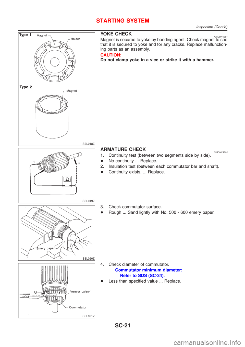
YOKE CHECKNJSC0019S04Magnet is secured to yoke by bonding agent. Check magnet to see
that it is secured to yoke and for any cracks. Replace malfunction-
ing parts as an assembly.
CAUTION:
Do not clamp yoke in a vice or strike it with a hammer.
SEL019Z
ARMATURE CHECKNJSC0019S051. Continuity test (between two segments side by side).
+No continuity ... Replace.
2. Insulation test (between each commutator bar and shaft).
+Continuity exists. ... Replace.
SEL020Z
3. Check commutator surface.
+Rough ... Sand lightly with No. 500 - 600 emery paper.
SEL021Z
4. Check diameter of commutator.
Commutator minimum diameter:
Refer to SDS (SC-34).
+Less than specified value ... Replace.
STARTING SYSTEM
Inspection (Cont'd)
SC-21
Page 2150 of 2493
CEL501
ReplacementNJEL0010For removal and installation of spiral cable, refer to RS-29,
ªInstallation Ð Air Bag Module and Spiral Cableº.
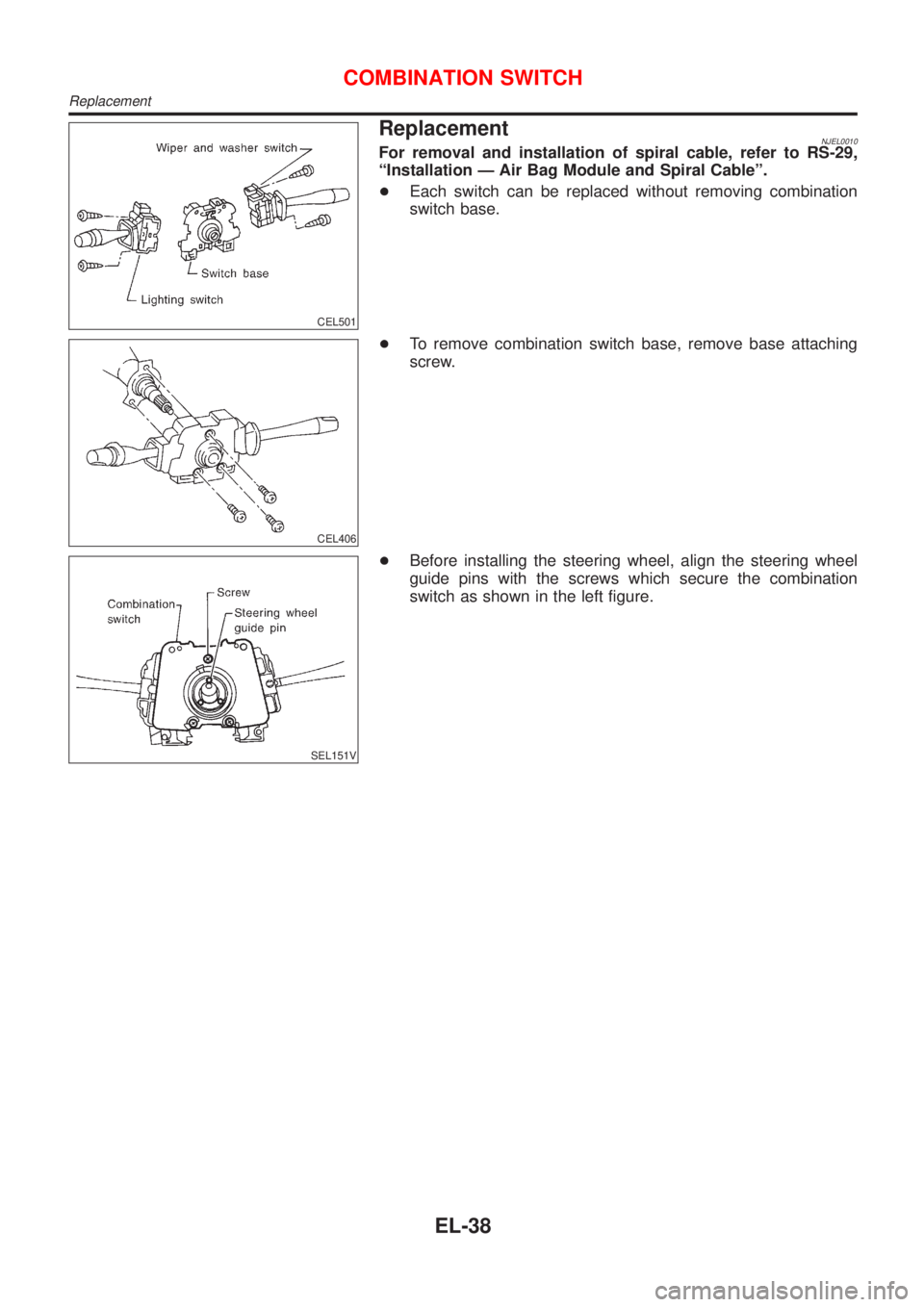
+Each switch can be replaced without removing combination
switch base.
CEL406
+To remove combination switch base, remove base attaching
screw.
SEL151V
+Before installing the steering wheel, align the steering wheel
guide pins with the screws which secure the combination
switch as shown in the left figure.
COMBINATION SWITCH
Replacement
EL-38
Page 2240 of 2493
RemovalNJEL0060S02011. Remove cowl top seal rubber and cowl top cover.
2. Remove wiper motor connector.
3. Remove 3 screws that secure wiper motor and wiper frame.
4. Detach wiper motor from wiper linkage at ball joint.
5. Remove wiper linkage.
Be careful not to break ball joint rubber boot.
InstallationNJEL0060S0202+Grease ball joint portion before installation.
1. Installation is the reverse order of removal.
GEL013-A
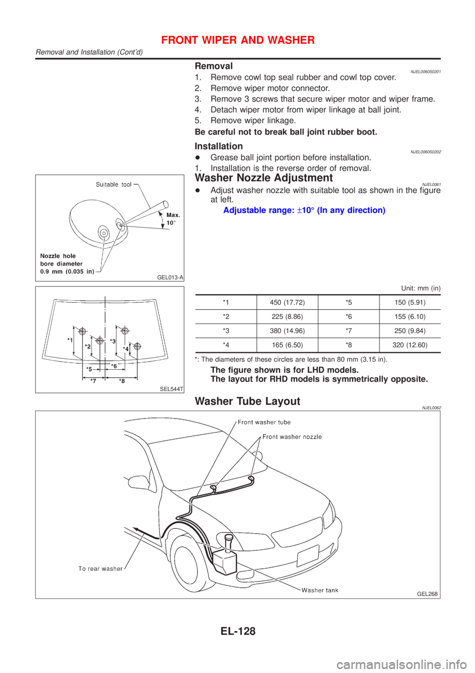
Washer Nozzle AdjustmentNJEL0061+Adjust washer nozzle with suitable tool as shown in the figure
at left.
Adjustable range:±10É (In any direction)
SEL544T
Unit: mm (in)
*1 450 (17.72) *5 150 (5.91)
*2 225 (8.86) *6 155 (6.10)
*3 380 (14.96) *7 250 (9.84)
*4 165 (6.50) *8 320 (12.60)
*: The diameters of these circles are less than 80 mm (3.15 in).
The figure shown is for LHD models.
The layout for RHD models is symmetrically opposite.
Washer Tube LayoutNJEL0062
GEL268
FRONT WIPER AND WASHER
Removal and Installation (Cont'd)
EL-128
Page 2261 of 2493
System Description=NJEL0497Refer to Owner's Manual for audio system operating instructions.
Power is supplied at all times
+through 15A fuse (No. 32, located in the fusible link and fuse block)
+to audio unit terminal 9
+to CD auto changer terminal 32.
With the ignition switch in the ACC or ON position, power is supplied
+through 10A fuse [No. 1, located in the fuse block (J/B)]
+to audio unit terminal 3,
+to CD auto changer terminal 36 and
Ground is supplied through the case of the audio unit.
Audio signals are supplied
+through audio unit terminals 7, 10, 11, 12, 13, 14, 15, 16
+to terminals 1 and 2 of front door speaker LH and RH,
+to terminals 1 and 2 of rear door speaker LH and RH and
+to terminals 1 and 2 of pillar tweeter LH and RH (with 6 speakers)
When the navigation system is triggered,
power is supplied
+through navi control unit terminal 46
+to speaker relay terminal 2
Ground is supplied
+through navi control unit terminal 44
+to speaker relay terminal 1
With power and ground supplied, the relay is energized, and then audio signal is interrupted to front door
speaker LH (LHD models) or RH (RHD models), and pillar tweeter LH (LHD models) or RH (RHD models)
For detailed, refer to ªNAVIGATION SYSTEMº.
NATS AUDIO LINKNJEL0497S01DescriptionNJEL0497S0101The link with the NATS IMMU implies that the audio unit can basically only be operated if connected to the
matching NATS IMMU to which the audio unit was initially fitted on the production line.
Since radio operation is impossible after the link with the NATS is disrupted theft of the audio unit is basically
useless since special equipment is required to reset the audio unit.
Initialization process for audio units that are linked to the NATS IMMU
New audio units will be delivered to the factories in the ªNEWº state, i.e. ready to be linked with the vehicle's
NATS. When the audio unit in ªNEWº state is first switched on at the factory, it will start up communication
with the vehicle's immobiliser control unit (IMMU) and send a code (the ªaudio unit Codeº) to the IMMU. The
IMMU will then store this code, which is unique to each audio unit, in its (permanent) memory.
Upon receipt of the code by the IMMU, the NATS will confirm correct receipt of the audio unit code to the audio
unit. Hereafter, the audio unit will operate as normal.
During the initialisation process, ªNEWº is displayed on the audio unit display. Normally though, communica-
tion between audio unit and IMMU takes such a short time (300 ms) that the audio unit seems to switch on
directly without showing ªNEWº on its display.
Normal operation
Each time the audio unit is switched on afterwards, the audio unit code will be verified between the audio unit
and the NATS before the audio unit becomes operational. During the code verification process, ªWAITº is
shown on the audio unit display. Again, the communication takes such a short time (300 ms) that the audio
unit seems to switch on directly without showing ªWAITº on its display.
When the radio is locked
In case of a audio unit being linked with the vehicle's NATS (immobilizer system), disconnection of the link
between the audio unit and the IMMU will cause the audio unit to switch into the lock (ªSECUREº) mode in
which the audio unit is fully inoperative. Hence, repair of the audio unit is basically impossible, unless the audio
unit is reset to the ªNEWº state for which special decoding equipment is required.
Clarion has provided their authorized service representatives with so called ªdecoder boxesº which can bring
the audio unit back to the ªNEWº state, enabling the audio unit to be switched on after which repair can be
AUDIO
System Description
EL-149
Page 2346 of 2493
Component Parts and Harness Connetor
Location
NJEL0406For details, refer to ªELECTRICAL UNIT LOCATIONº (EL-319) and
ªHARNESS LAYOUTº (EL-324).
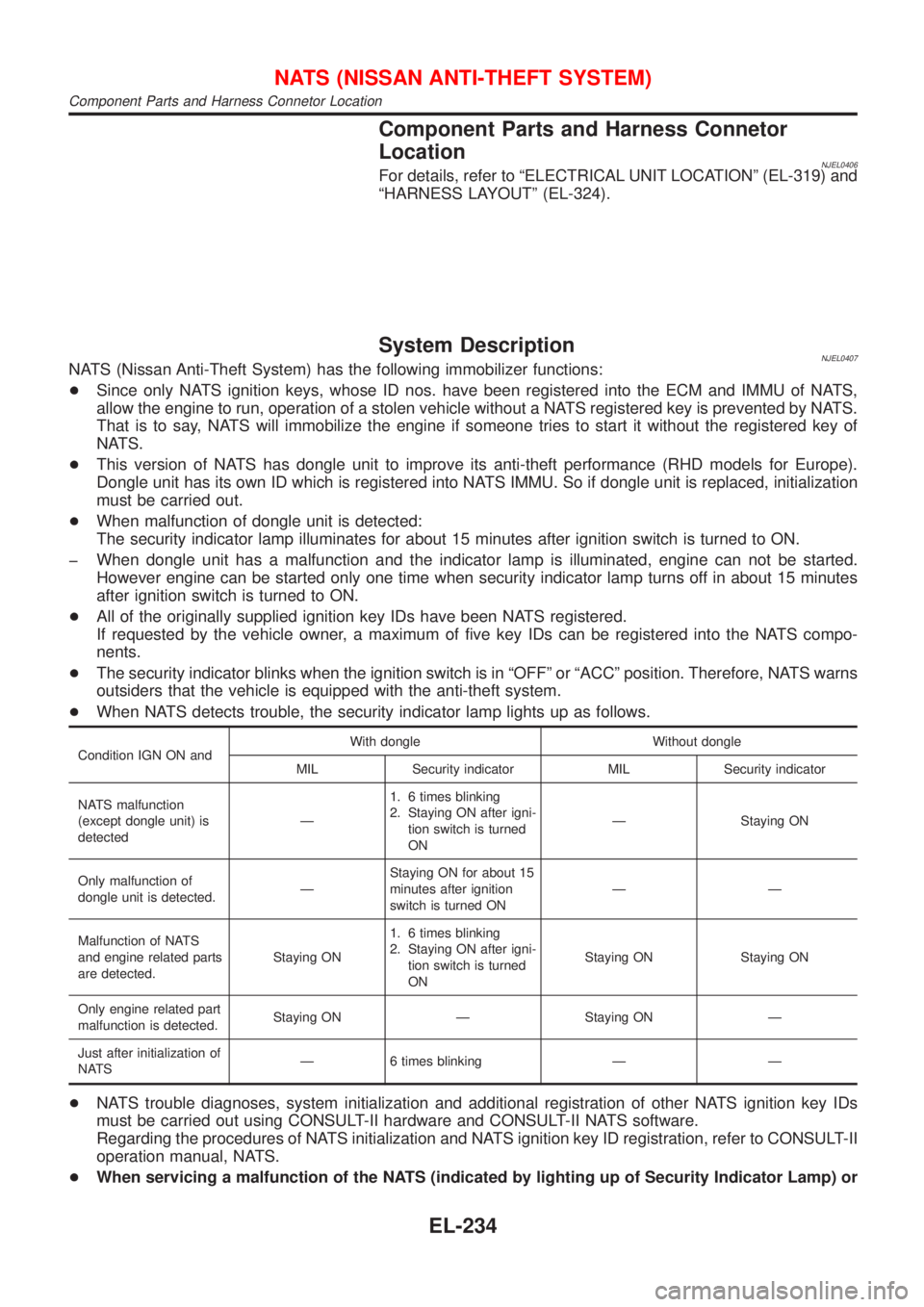
System DescriptionNJEL0407NATS (Nissan Anti-Theft System) has the following immobilizer functions:
+Since only NATS ignition keys, whose ID nos. have been registered into the ECM and IMMU of NATS,
allow the engine to run, operation of a stolen vehicle without a NATS registered key is prevented by NATS.
That is to say, NATS will immobilize the engine if someone tries to start it without the registered key of
NATS.
+This version of NATS has dongle unit to improve its anti-theft performance (RHD models for Europe).
Dongle unit has its own ID which is registered into NATS IMMU. So if dongle unit is replaced, initialization
must be carried out.
+When malfunction of dongle unit is detected:
The security indicator lamp illuminates for about 15 minutes after ignition switch is turned to ON.
þ When dongle unit has a malfunction and the indicator lamp is illuminated, engine can not be started.
However engine can be started only one time when security indicator lamp turns off in about 15 minutes
after ignition switch is turned to ON.
+All of the originally supplied ignition key IDs have been NATS registered.
If requested by the vehicle owner, a maximum of five key IDs can be registered into the NATS compo-
nents.
+The security indicator blinks when the ignition switch is in ªOFFº or ªACCº position. Therefore, NATS warns
outsiders that the vehicle is equipped with the anti-theft system.
+When NATS detects trouble, the security indicator lamp lights up as follows.
Condition IGN ON andWith dongle Without dongle
MIL Security indicator MIL Security indicator
NATS malfunction
(except dongle unit) is
detectedÐ1. 6 times blinking
2. Staying ON after igni-
tion switch is turned
ONÐ Staying ON
Only malfunction of
dongle unit is detected.ÐStaying ON for about 15
minutes after ignition
switch is turned ONÐÐ
Malfunction of NATS
and engine related parts
are detected.Staying ON1. 6 times blinking
2. Staying ON after igni-
tion switch is turned
ONStaying ON Staying ON
Only engine related part
malfunction is detected.Staying ON Ð Staying ON Ð
Just after initialization of
NATSÐ 6 times blinking Ð Ð
+NATS trouble diagnoses, system initialization and additional registration of other NATS ignition key IDs
must be carried out using CONSULT-II hardware and CONSULT-II NATS software.
Regarding the procedures of NATS initialization and NATS ignition key ID registration, refer to CONSULT-II
operation manual, NATS.
+When servicing a malfunction of the NATS (indicated by lighting up of Security Indicator Lamp) or
NATS (NISSAN ANTI-THEFT SYSTEM)
Component Parts and Harness Connetor Location
EL-234
Page 2348 of 2493
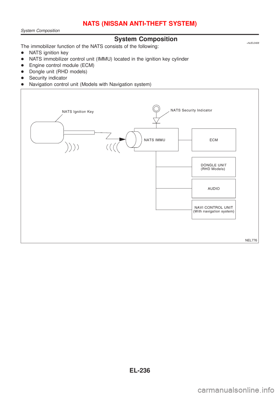
System Composition=NJEL0408The immobilizer function of the NATS consists of the following:
+NATS ignition key
+NATS immobilizer control unit (IMMU) located in the ignition key cylinder
+Engine control module (ECM)
+Dongle unit (RHD models)
+Security indicator
+Navigation control unit (Models with Navigation system)
NEL776
NATS (NISSAN ANTI-THEFT SYSTEM)
System Composition
EL-236
Page 2351 of 2493
CONSULT-II DIAGNOSTIC TEST MODE FUNCTION=NJEL0410S02
CONSULT-II DIAGNOSTIC TEST
MODEDescription
C/U INITIALIZATION When replacing any of the following components, C/U initialization and re-registration of all
NATS ignition keys are necessary.
[NATS ignition key/IMMU/ECM/Dongle unit]
SELF-DIAG RESULTS Detected items (screen terms) are as shown in the chart EL-239.
NOTE:
+When any initialization is performed, all ID previously reg-
istered will be erased and all NATS ignition keys must be
registered again.
+The engine cannot be started with an unregistered key. In this
case, the system may show ªDIFFERENCE OF KEYº or
ªLOCK MODEº as a self-diagnostic result on the CONSULT-II
screen.
+When initialization is performed for RHD models for Europe,
security indicator will flash six times to demonstrate recognition
of the dongle unit ID.
+In rare case, ªCHAIN OF ECM-IMMUº might be stored as a
self-diagnostic result during key registration procedure, even if
the system is not malfunctioning.
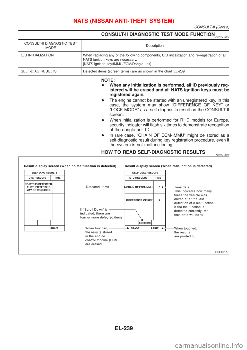
HOW TO READ SELF-DIAGNOSTIC RESULTSNJEL0410S03
SEL151X
NATS (NISSAN ANTI-THEFT SYSTEM)
CONSULT-II (Cont'd)
EL-239
Page 2352 of 2493
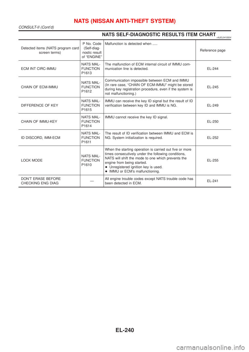
NATS SELF-DIAGNOSTIC RESULTS ITEM CHART=NJEL0410S04
Detected items (NATS program card
screen terms)P No. Code
(Self-diag-
nostic result
of ªENGINEºMalfunction is detected when .....
Reference page
ECM INT CIRC-IMMUNATS MAL-
FUNCTION
P1613The malfunction of ECM internal circuit of IMMU com-
munication line is detected. EL-244
CHAIN OF ECM-IMMUNATS MAL-
FUNCTION
P1612Communication impossible between ECM and IMMU
(In rare case, ªCHAIN OF ECM-IMMUº might be stored
during key registration procedure, even if the system is
not malfunctioning.)EL-245
DIFFERENCE OF KEYNATS MAL-
FUNCTION
P1615IMMU can receive the key ID signal but the result of ID
verification between key ID and IMMU is NG. EL-249
CHAIN OF IMMU-KEYNATS MAL-
FUNCTION
P1614IMMU cannot receive the key ID signal.
EL-250
ID DISCORD, IMM-ECMNATS MAL-
FUNCTION
P1611The result of ID verification between IMMU and ECM is
NG. System initialization is required. EL-252
LOCK MODENATS MAL-
FUNCTION
P1610When the starting operation is carried out five or more
times consecutively under the following conditions,
NATS will shift the mode to one which prevents the
engine from being started.
+Unregistered ignition key is used.
+IMMU or ECM's malfunctioning.EL-255
DON'T ERASE BEFORE
CHECKING ENG DIAGÐAll engine trouble codes except NATS trouble code has
been detected in ECM.EL-241
NATS (NISSAN ANTI-THEFT SYSTEM)
CONSULT-II (Cont'd)
EL-240