2001 NISSAN ALMERA N16 ECU
[x] Cancel search: ECUPage 1843 of 2493
SRS444
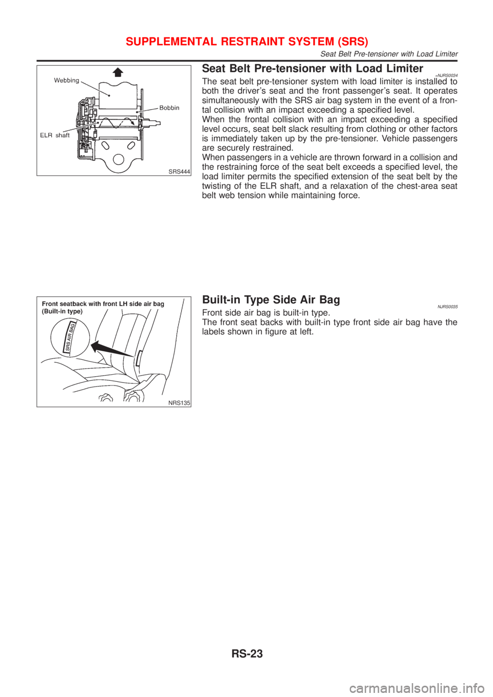
Seat Belt Pre-tensioner with Load Limiter=NJRS0034The seat belt pre-tensioner system with load limiter is installed to
both the driver's seat and the front passenger's seat. It operates
simultaneously with the SRS air bag system in the event of a fron-
tal collision with an impact exceeding a specified level.
When the frontal collision with an impact exceeding a specified
level occurs, seat belt slack resulting from clothing or other factors
is immediately taken up by the pre-tensioner. Vehicle passengers
are securely restrained.
When passengers in a vehicle are thrown forward in a collision and
the restraining force of the seat belt exceeds a specified level, the
load limiter permits the specified extension of the seat belt by the
twisting of the ELR shaft, and a relaxation of the chest-area seat
belt web tension while maintaining force.
NRS135
Built-in Type Side Air BagNJRS0035Front side air bag is built-in type.
The front seat backs with built-in type front side air bag have the
labels shown in figure at left.
SUPPLEMENTAL RESTRAINT SYSTEM (SRS)
Seat Belt Pre-tensioner with Load Limiter
RS-23
Page 1850 of 2493
SRS443
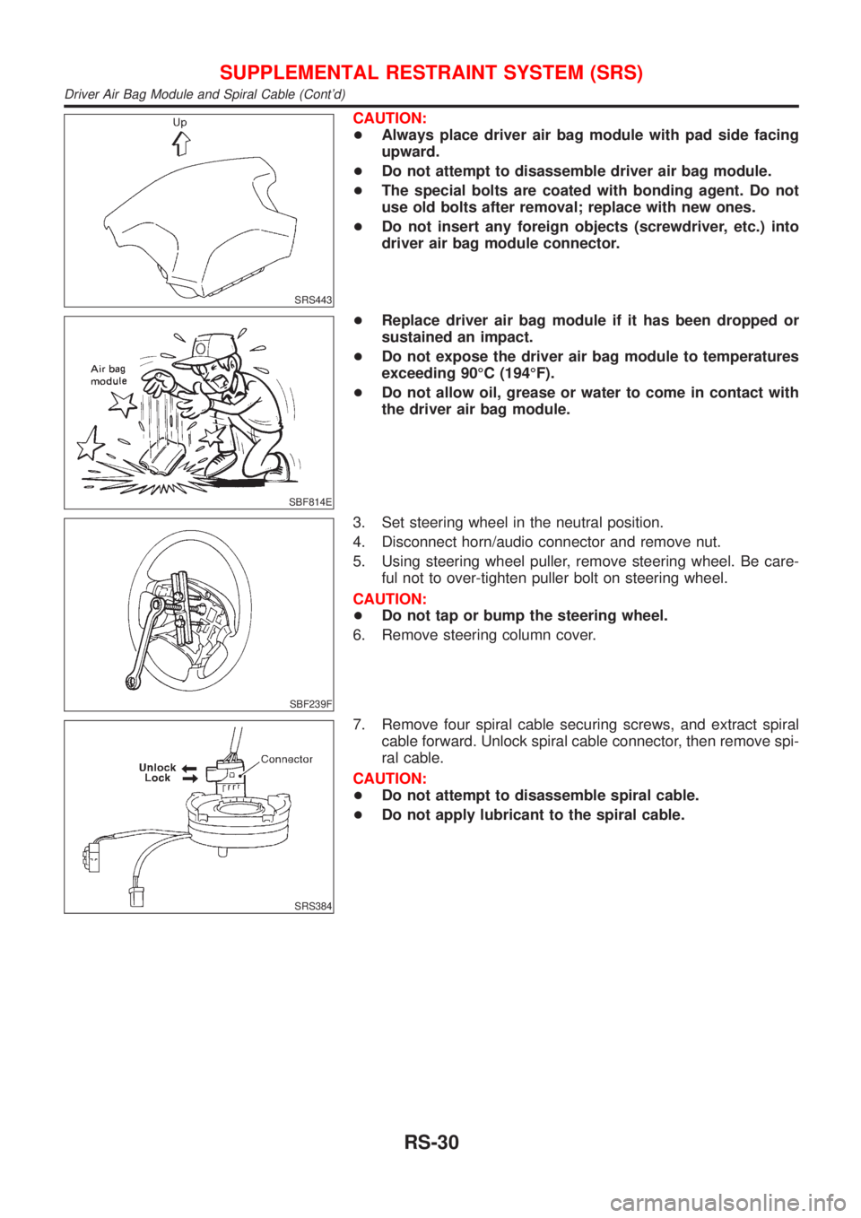
CAUTION:
+Always place driver air bag module with pad side facing
upward.
+Do not attempt to disassemble driver air bag module.
+The special bolts are coated with bonding agent. Do not
use old bolts after removal; replace with new ones.
+Do not insert any foreign objects (screwdriver, etc.) into
driver air bag module connector.
SBF814E
+Replace driver air bag module if it has been dropped or
sustained an impact.
+Do not expose the driver air bag module to temperatures
exceeding 90ÉC (194ÉF).
+Do not allow oil, grease or water to come in contact with
the driver air bag module.
SBF239F
3. Set steering wheel in the neutral position.
4. Disconnect horn/audio connector and remove nut.
5. Using steering wheel puller, remove steering wheel. Be care-
ful not to over-tighten puller bolt on steering wheel.
CAUTION:
+Do not tap or bump the steering wheel.
6. Remove steering column cover.
SRS384
7. Remove four spiral cable securing screws, and extract spiral
cable forward. Unlock spiral cable connector, then remove spi-
ral cable.
CAUTION:
+Do not attempt to disassemble spiral cable.
+Do not apply lubricant to the spiral cable.
SUPPLEMENTAL RESTRAINT SYSTEM (SRS)
Driver Air Bag Module and Spiral Cable (Cont'd)
RS-30
Page 1853 of 2493
SRS825
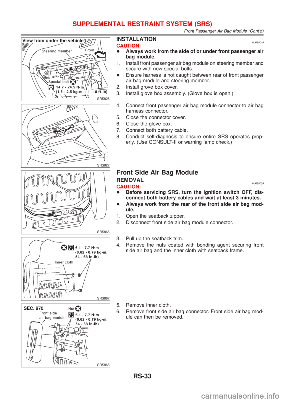
INSTALLATIONNJRS0019CAUTION:
+Always work from the side of or under front passenger air
bag module.
1. Install front passenger air bag module on steering member and
secure with new special bolts.
+Ensure harness is not caught between rear of front passenger
air bag module and steering member.
2. Install grove box cover.
3. Install glove box assembly. (Glove box is open.)
SRS827
4. Connect front passenger air bag module connector to air bag
harness connector.
5. Close the connector cover.
6. Close the glove box.
7. Connect both battery cable.
8. Conduct self-diagnosis to ensure entire SRS operates prop-
erly. (Use CONSULT-II or warning lamp check.)
SRS866
Front Side Air Bag Module
REMOVALNJRS0059CAUTION:
+Before servicing SRS, turn the ignition switch OFF, dis-
connect both battery cables and wait at least 3 minutes.
+Always work from the rear of the front side air bag mod-
ule.
1. Open the seatback zipper.
2. Disconnect front side air bag module connector.
SRS867
3. Pull up the seatback trim.
4. Remove the nuts coated with bonding agent securing front
side air bag and the inner cloth with seatback frame.
SRS868
5. Remove inner cloth.
6. Remove front side air bag connector. Front side air bag mod-
ule can then be removed.
SUPPLEMENTAL RESTRAINT SYSTEM (SRS)
Front Passenger Air Bag Module (Cont'd)
RS-33
Page 1854 of 2493
SRS869
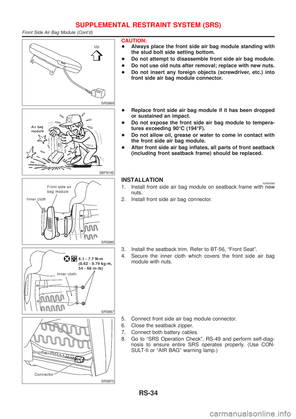
CAUTION:
+Always place the front side air bag module standing with
the stud bolt side setting bottom.
+Do not attempt to disassemble front side air bag module.
+Do not use old nuts after removal; replace with new nuts.
+Do not insert any foreign objects (screwdriver, etc.) into
front side air bag module connector.
SBF814E
+Replace front side air bag module if it has been dropped
or sustained an impact.
+Do not expose the front side air bag module to tempera-
tures exceeding 90ÉC (194ÉF).
+Do not allow oil, grease or water to come in contact with
the front side air bag module.
+After front side air bag inflates, all parts of front seatback
(including front seatback frame) should be replaced.
SRS885
INSTALLATIONNJRS00601. Install front side air bag module on seatback frame with new
nuts.
2. Install front side air bag connector.
SRS867
3. Install the seatback trim. Refer to BT-56, ªFront Seatº.
4. Secure the inner cloth which covers the front side air bag
module with nuts.
SRS870
5. Connect front side air bag module connector.
6. Close the seatback zipper.
7. Connect both battery cables.
8. Go to ªSRS Operation Checkº, RS-49 and perform self-diag-
nosis to ensure entire SRS operates properly. (Use CON-
SULT-II or ªAIR BAGº warning lamp.)
SUPPLEMENTAL RESTRAINT SYSTEM (SRS)
Front Side Air Bag Module (Cont'd)
RS-34
Page 1856 of 2493
SBF266H
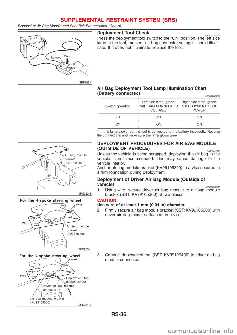
Deployment Tool CheckNJRS0022S0102Press the deployment tool switch to the ªONº position. The left side
lamp in the tool, marked ªair bag connector voltageº should illumi-
nate. If it does not illuminate, replace the tool.
Air Bag Deployment Tool Lamp Illumination Chart
(Battery connected)
NJRS0022S0103
Switch operationLeft side lamp, green*
ªAIR BAG CONNECTOR
VOLTAGEºRight side lamp, green*
ªDEPLOYMENT TOOL
POWERº
OFF OFF ON
ON ON ON
*: If this lamp glows red, the tool is connected to the battery incorrectly. Reverse
the connections and make sure the lamp glows green.
SRS232-E
SRS233-E
DEPLOYMENT PROCEDURES FOR AIR BAG MODULE
(OUTSIDE OF VEHICLE)
NJRS0022S02Unless the vehicle is being scrapped, deploying the air bag in the
vehicle is not recommended. This may cause damage to the
vehicle interior.
Anchor air bag module bracket (KV99105300) in a vise secured to
a firm foundation during deployment.
Deployment of Driver Air Bag Module (Outside of
vehicle)
NJRS0022S02011. Using wire, secure driver air bag module to air bag module
bracket (SST: KV99105300) at two places.
CAUTION:
Use wire of at least 1 mm (0.04 in) diameter.
2. Firmly secure air bag module bracket (SST: KV99105300) with
driver air bag module attached, in a vise.
SRS234-E
3. Connect deployment tool (SST: KV99106400) to driver air bag
module connector.
SUPPLEMENTAL RESTRAINT SYSTEM (SRS)
Disposal of Air Bag Module and Seat Belt Pre-tensioner (Cont'd)
RS-36
Page 1857 of 2493
SRS020-A
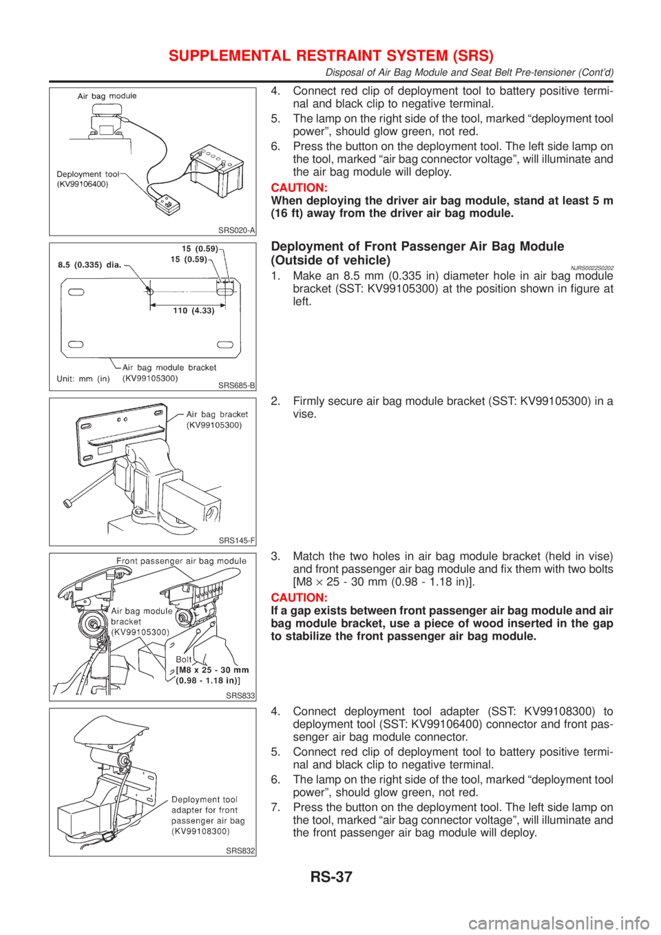
4. Connect red clip of deployment tool to battery positive termi-
nal and black clip to negative terminal.
5. The lamp on the right side of the tool, marked ªdeployment tool
powerº, should glow green, not red.
6. Press the button on the deployment tool. The left side lamp on
the tool, marked ªair bag connector voltageº, will illuminate and
the air bag module will deploy.
CAUTION:
When deploying the driver air bag module, stand at least 5 m
(16 ft) away from the driver air bag module.
SRS685-B
Deployment of Front Passenger Air Bag Module
(Outside of vehicle)
NJRS0022S02021. Make an 8.5 mm (0.335 in) diameter hole in air bag module
bracket (SST: KV99105300) at the position shown in figure at
left.
SRS145-F
2. Firmly secure air bag module bracket (SST: KV99105300) in a
vise.
SRS833
3. Match the two holes in air bag module bracket (held in vise)
and front passenger air bag module and fix them with two bolts
[M8´25 - 30 mm (0.98 - 1.18 in)].
CAUTION:
If a gap exists between front passenger air bag module and air
bag module bracket, use a piece of wood inserted in the gap
to stabilize the front passenger air bag module.
SRS832
4. Connect deployment tool adapter (SST: KV99108300) to
deployment tool (SST: KV99106400) connector and front pas-
senger air bag module connector.
5. Connect red clip of deployment tool to battery positive termi-
nal and black clip to negative terminal.
6. The lamp on the right side of the tool, marked ªdeployment tool
powerº, should glow green, not red.
7. Press the button on the deployment tool. The left side lamp on
the tool, marked ªair bag connector voltageº, will illuminate and
the front passenger air bag module will deploy.
SUPPLEMENTAL RESTRAINT SYSTEM (SRS)
Disposal of Air Bag Module and Seat Belt Pre-tensioner (Cont'd)
RS-37
Page 1858 of 2493
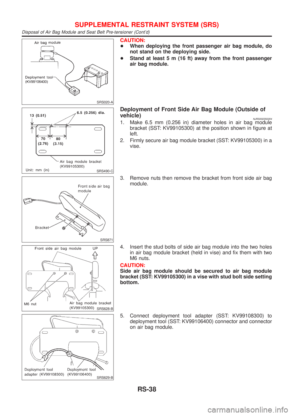
SRS020-A
CAUTION:
+When deploying the front passenger air bag module, do
not stand on the deploying side.
+Stand at least 5 m (16 ft) away from the front passenger
air bag module.
SRS490-C
Deployment of Front Side Air Bag Module (Outside of
vehicle)
NJRS0022S02041. Make 6.5 mm (0.256 in) diameter holes in air bag module
bracket (SST: KV99105300) at the position shown in figure at
left.
2. Firmly secure air bag module bracket (SST: KV99105300) in a
vise.
SRS871
3. Remove nuts then remove the bracket from front side air bag
module.
SRS628-B
4. Insert the stud bolts of side air bag module into the two holes
in air bag module bracket (held in vise) and fix them with two
M6 nuts.
CAUTION:
Side air bag module should be secured to air bag module
bracket (SST: KV99105300) in a vise with stud bolt side setting
bottom.
SRS629-B
5. Connect deployment tool adapter (SST: KV99108300) to
deployment tool (SST: KV99106400) connector and connector
on air bag module.
SUPPLEMENTAL RESTRAINT SYSTEM (SRS)
Disposal of Air Bag Module and Seat Belt Pre-tensioner (Cont'd)
RS-38
Page 1861 of 2493
Trouble Diagnoses Introduction=NJRS0043CAUTION:
+Do not use electrical test equipment on any circuit related to the SRS unless instructed to in this
Service Manual. SRS wiring harnesses can be identified by yellow harness connector.
+Do not attempt to repair, splice or modify the SRS wiring harness. If the harness is damaged,
replace it with a new one.
+Keep ground portion clean.
DIAGNOSIS FUNCTIONNJRS0043S01The SRS self-diagnosis results can be read by using ªAIR BAGº warning lamp and/or CONSULT-II. The read-
ing of these results is accomplished using one of two modes Ð ªUser modeº and ªDiagnosis modeº.
The User mode is exclusively prepared for the customer (driver). This mode warns the driver of a system
malfunction through the operation of the ªAIR BAGº warning lamp.
The Diagnosis mode allows the technician to locate and inspect the malfunctioning part.
The mode applications for the ªAIR BAGº warning lamp and CONSULT-II are as follows:
User mode Diagnosis mode Display type
ªAIR BAGº warning lamp X X ON-OFF operation
CONSULT-II Ð X Monitoring
NOTE:
Seat belt pre-tensioner malfunction is indicated by ªAIR BAGº warning lamp.
DIAGNOSIS MODE FOR CONSULT-IINJRS0043S02+ªSELF-DIAG [CURRENT]º
A current Self-diagnosis result (also indicated by the number of warning lamp flashes in the Diagnosis
mode) is displayed on the CONSULT-II screen in real time. This refers to a malfunctioning part requiring
repairs.
+ªSELF-DIAG [PAST]º
Diagnosis results previously stored in the memory are displayed on the CONSULT-II screen. The stored
results are not erased until memory erasing is executed.
+ªTROUBLE DIAG RECORDº
With TROUBLE DIAG RECORD, diagnosis results previously erased by a reset operation can be displayed
on the CONSULT-II screen.
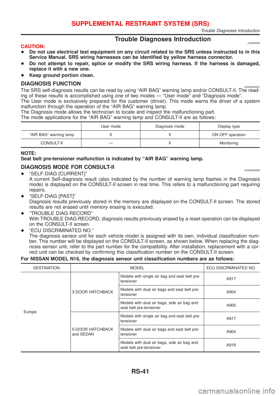
+ªECU DISCRIMINATED NO.º
The diagnosis sensor unit for each vehicle model is assigned with its own, individual classification num-
ber. This number will be displayed on the CONSULT-II screen, as shown below. When replacing the diag-
nosis sensor unit, refer to the part number for the compatibility. After installation, replacement with a cor-
rect unit can be checked by confirming this classification number on the CONSULT-II screen.
For NISSAN MODEL N16, the diagnosis sensor unit classification numbers are as follows:
DESTINATION MODEL ECU DISCRIMINATED NO.
Europe3-DOOR HATCHBACKModels with single air bag and seat belt pre-
tensionerA917
Models with dual air bags and seat belt pre-
tensionerA904
Models with dual air bags, side air bag and
seat belt pre-tensionerA905
5-DOOR HATCHBACK
and SEDANModels with single air bag and seat belt pre-
tensionerA917
Models with dual air bags and seat belt pre-
tensionerA904
Models with dual air bags, side air bag and
seat belt pre-tensionerA918
SUPPLEMENTAL RESTRAINT SYSTEM (SRS)
Trouble Diagnoses Introduction
RS-41