Page 1513 of 2493
DIAGNOSTIC PROCEDURENJAT0351S02
1 CHECK PNP SWITCH CIRCUIT (With CONSULT-II)
With CONSULT-II
1. Turn ignition switch to ªONº position.
(Do not start engine.)
2. Select ªECU INPUT SIGNALSº in ªDATA MONITORº mode for ªA/Tº with CONSULT-II.
3. Read out ªP/Nº, ªRº, ªDº, ª2º and ª1º position switches moving selector lever to each position.
Check that the signal of the selector lever position is indicated properly.
SAT701J
OK or NG
OK©GO TO 3.
NG©Check the following items:
+PNP switch (Refer to ªComponent Inspectionº, AT-333.)
+Harness for short or open between ignition switch and PNP switch (Main harness)
+Harness for short or open between PNP switch and TCM (Main harness)
+Diode (P, N positions)
TROUBLE DIAGNOSES FOR SYMPTOMS
21. TCM Self-diagnosis Does Not Activate (PNP, Overdrive Control and Throttle Position Switches Circuit Checks) (Cont'd)
AT-327
Page 1515 of 2493
3 CHECK OVERDRIVE CONTROL SWITCH CIRCUIT (With CONSULT-II)
With CONSULT-II
1. Turn ignition switch to ªONº position.
(Do not start engine.)
2. Select ªECU INPUT SIGNALSº in ªDATA MONITORº mode for ªA/Tº with CONSULT-II.
3. Read out ªOVERDRIVE SWITCHº.
Check the signal of the overdrive control switch is indicated properly.
(Overdrive control switch ªONº displayed on CONSULT-II means overdrive ªOFFº.)
SAT645J
OK or NG
OK©GO TO 5.
NG©Check the following items:
+Overdrive control switch (Refer to ªComponent Inspectionº, AT-333.)
+Harness for short or open between TCM and overdrive control switch (Main harness)
+Harness of ground circuit for overdrive control switch (Main harness) for short or open
TROUBLE DIAGNOSES FOR SYMPTOMS
21. TCM Self-diagnosis Does Not Activate (PNP, Overdrive Control and Throttle Position Switches Circuit Checks) (Cont'd)
AT-329
Page 1517 of 2493

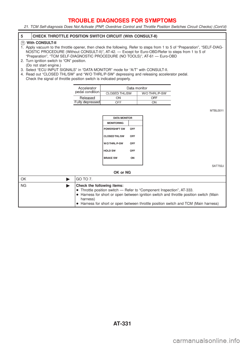
5 CHECK THROTTLE POSITION SWITCH CIRCUIT (With CONSULT-II)
With CONSULT-II
1. Apply vacuum to the throttle opener, then check the following. Refer to steps from 1 to 5 of ªPreparationº, ªSELF-DIAG-
NOSTIC PROCEDURE (Without CONSULT-II)º, AT-42. Ð Except for Euro-OBD/Refer to steps from 1 to 5 of
ªPreparationº, ªTCM SELF-DIAGNOSTIC PROCEDURE (NO TOOLS)º, AT-61 Ð Euro-OBD
2. Turn ignition switch to ªONº position.
(Do not start engine.)
3. Select ªECU INPUT SIGNALSº in ªDATA MONITORº mode for ªA/Tº with CONSULT-II.
4. Read out ªCLOSED THL/SWº and ªW/O THRL/P-SWº depressing and releasing accelerator pedal.
Check the signal of throttle position switch is indicated properly.
MTBL0011
SAT702J
OK or NG
OK©GO TO 7.
NG©Check the following items:
+Throttle position switch Ð Refer to ªComponent Inspectionº, AT-333.
+Harness for short or open between ignition switch and throttle position switch (Main
harness)
+Harness for short or open between throttle position switch and TCM (Main harness)
TROUBLE DIAGNOSES FOR SYMPTOMS
21. TCM Self-diagnosis Does Not Activate (PNP, Overdrive Control and Throttle Position Switches Circuit Checks) (Cont'd)
AT-331
Page 1527 of 2493
ComponentsNJAT0107
SAT996J
CAUTION:
+Install key interlock cable in such a way that it will not be
damaged by sharp bends, twists or interference with adja-
cent parts.
+After installing key interlock cable to control device, make
sure that casing cap and bracket are firmly secured in
their positions.
SAT853J
RemovalNJAT01081. Unlock slider by squeezing lock tabs on slider from adjuster
holder and remove interlock rod from cable.
KEY INTERLOCK CABLE
Components
AT-341
Page 1533 of 2493

AAT259A
14. Remove rear plate cover.
15. Remove torque converter bolts.
Rotate crankshaft to gain access to securing bolts.
16. Remove rear transaxle to engine bracket. Refer to EM-49,
ªREMOVAL AND INSTALLATIONº.
17. Support engine with a jack.
18. Remove rear transaxle mount. Refer to EM-49, ªREMOVAL
AND INSTALLATIONº.
19. Remove lower bolts fixing transaxle to engine.
20. Lower transaxle while supporting it with a jack.
SAT977H
InstallationNJAT01161. Check drive plate runout.
CAUTION:
Do not allow any magnetic materials to contact the ring gear
teeth.
Maximum allowable runout:
Refer to EM-60, ªFLYWHEEL/DRIVE PLATE
RUNOUTº.
+If this runout is out of allowance, replace drive plate with ring
gear.
SAT573D
2. When connecting torque converter to transaxle, measure dis-
tance ªAº to be certain that they are correctly assembled.
Distance ªAº:
15.9 mm (0.626 in) or more
AAT266A
3. Install torque converter to drive plate.
+With converter installed, rotate crankshaft several turns to
check that transaxle rotates freely without binding.
SAT029K
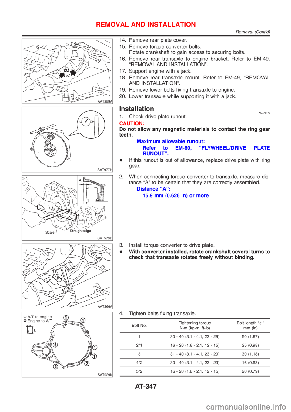
4. Tighten belts fixing transaxle.
Bolt No.Tightening torque
N´m (kg-m, ft-lb)Bolt length ª!º
mm (in)
1 30 - 40 (3.1 - 4.1, 23 - 29) 50 (1.97)
2*1 16 - 20 (1.6 - 2.1, 12 - 15) 25 (0.98)
3 31 - 40 (3.1 - 4.1, 23 - 29) 30 (1.18)
4*2 30 - 40 (3.1 - 4.1, 23 - 29) 16 (0.63)
5*2 16 - 20 (1.6 - 2.1, 12 - 15) 20 (0.79)
REMOVAL AND INSTALLATION
Removal (Cont'd)
AT-347
Page 1546 of 2493
SAT037DA
28. Remove brake band according to the following procedures.
a. Loosen lock nut, then back off anchor end pin.
+Do not reuse anchor end pin.
SAT038D
b. Remove brake band from transmission case.
SAT039D
+To prevent brake linings from cracking or peeling, do not
stretch the flexible band unnecessarily. When removing
the brake band, always secure it with a clip as shown in
the figure at left.
Leave the clip in position after removing the brake band.
SAT040D
c. Check brake band facing for damage, cracks, wear or burns.
SAT041D
29. Remove input shaft assembly (high clutch) and reverse clutch
according to the following procedures.
a. Remove input shaft assembly (high clutch) with reverse clutch.
DISASSEMBLY
AT-360
Page 1660 of 2493

Support BearingNJAX0018S05Make sure wheel bearing rolls freely and is free from noise, cracks,
pitting or wear.
Support Bearing BracketNJAX0018S06Check support bearing bracket for cracks with a magnetic explora-
tion or dyeing test.
ASSEMBLYNJAX0019+After drive shaft has been assembled, ensure that it
moves smoothly over its entire range without binding.
+Use NISSAN GENUINE GREASE or equivalent after every
overhaul.
SFA800
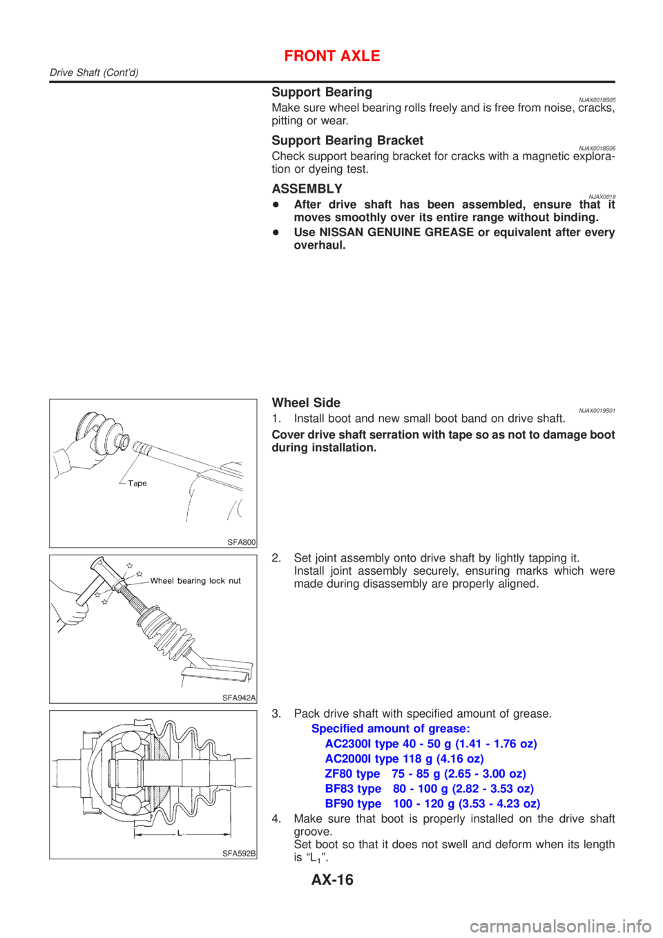
Wheel SideNJAX0019S011. Install boot and new small boot band on drive shaft.
Cover drive shaft serration with tape so as not to damage boot
during installation.
SFA942A
2. Set joint assembly onto drive shaft by lightly tapping it.
Install joint assembly securely, ensuring marks which were
made during disassembly are properly aligned.
SFA592B
3. Pack drive shaft with specified amount of grease.
Specified amount of grease:
AC2300I type 40 - 50 g (1.41 - 1.76 oz)
AC2000I type 118 g (4.16 oz)
ZF80 type 75 - 85 g (2.65 - 3.00 oz)
BF83 type 80 - 100 g (2.82 - 3.53 oz)
BF90 type 100 - 120 g (3.53 - 4.23 oz)
4. Make sure that boot is properly installed on the drive shaft
groove.
Set boot so that it does not swell and deform when its length
is ªL
1º.
FRONT AXLE
Drive Shaft (Cont'd)
AX-16
Page 1661 of 2493
Length ªL1º:
AC2300I type 94 - 96 mm (3.70 - 3.78 in)
AC2000I type 90 mm (3.54 in)
ZF80 type 91.4 - 91.6 mm (3.598 - 3.606 in)
BF83 type 95 mm (3.74 in)
BF90 type 85.5 mm (3.366 in)
SFA443B
5. Lock new larger and smaller boot bands securely with a suit-
able tool.
SFA313B
Dynamic Damper (Where Fitted)NJAX0019S021. Use new damper bands when installing.
2. Install dynamic damper from stationary-joint side while holding
it securely.
Length:
Refer to AX-21, SDS.
SFA800
Transaxle Side (TS70C, TS79C, TS83, DS90, DS83,
GI2000I and GI2300I types)
NJAX0019S031. Install boot and new small boot band on drive shaft.
Cover drive shaft serration with tape so as not to damage boot
during installation.
SFA514A
2. Install ball cage, inner race and balls or spider assembly as a
unit, making sure the marks which were made during disas-
sembly are properly aligned.
3. Install new snap ring.
FRONT AXLE
Drive Shaft (Cont'd)
AX-17