Page 1715 of 2395
SEM177F
SEM456G
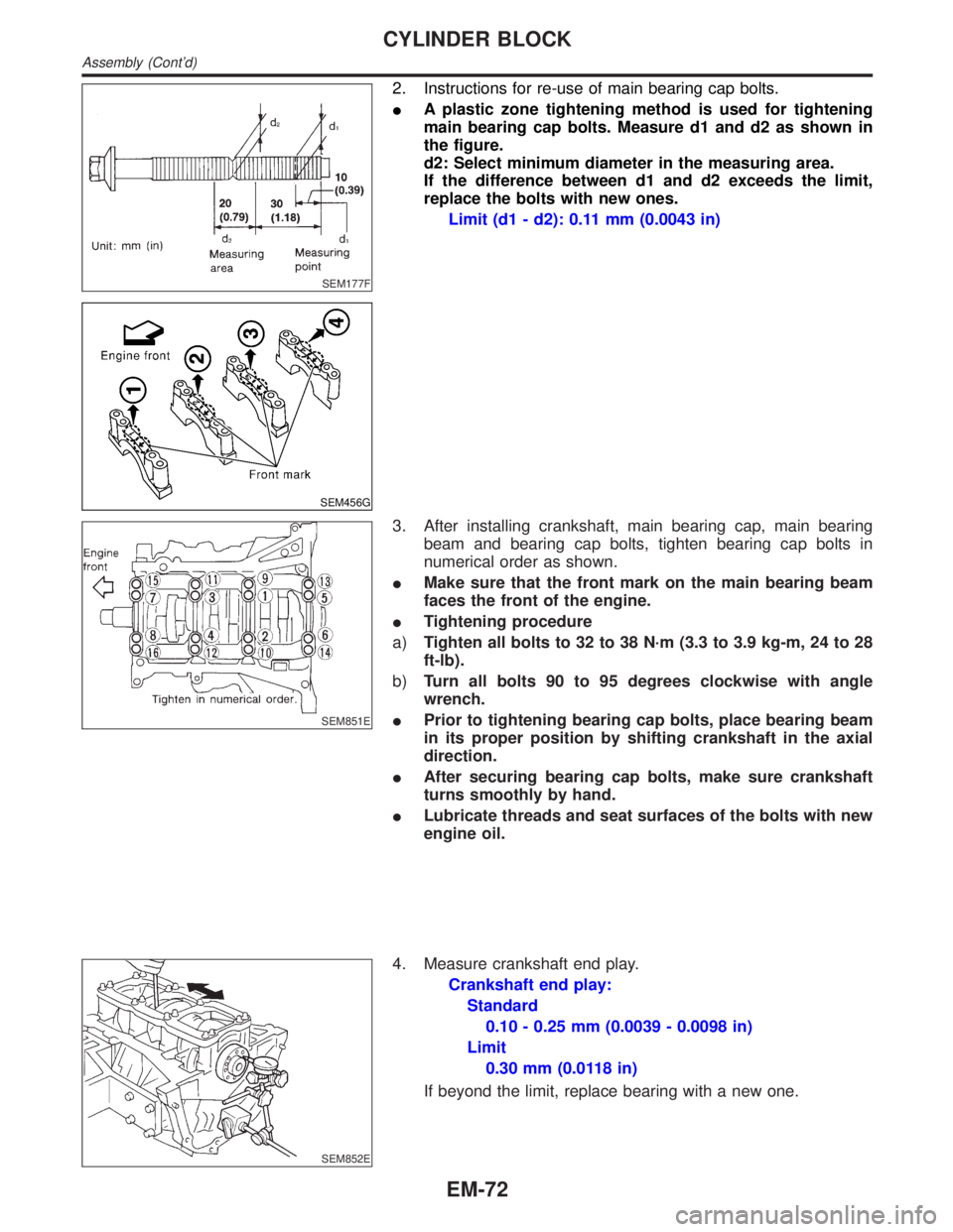
2. Instructions for re-use of main bearing cap bolts.
IA plastic zone tightening method is used for tightening
main bearing cap bolts. Measure d1 and d2 as shown in
the figure.
d2: Select minimum diameter in the measuring area.
If the difference between d1 and d2 exceeds the limit,
replace the bolts with new ones.
Limit (d1 - d2): 0.11 mm (0.0043 in)
SEM851E
3. After installing crankshaft, main bearing cap, main bearing
beam and bearing cap bolts, tighten bearing cap bolts in
numerical order as shown.
IMake sure that the front mark on the main bearing beam
faces the front of the engine.
ITightening procedure
a)Tighten all bolts to 32 to 38 N´m (3.3 to 3.9 kg-m, 24 to 28
ft-lb).
b)Turn all bolts 90 to 95 degrees clockwise with angle
wrench.
IPrior to tightening bearing cap bolts, place bearing beam
in its proper position by shifting crankshaft in the axial
direction.
IAfter securing bearing cap bolts, make sure crankshaft
turns smoothly by hand.
ILubricate threads and seat surfaces of the bolts with new
engine oil.
SEM852E
4. Measure crankshaft end play.
Crankshaft end play:
Standard
0.10 - 0.25 mm (0.0039 - 0.0098 in)
Limit
0.30 mm (0.0118 in)
If beyond the limit, replace bearing with a new one.
CYLINDER BLOCK
Assembly (Cont'd)
EM-72
Page 1716 of 2395
SEM455G
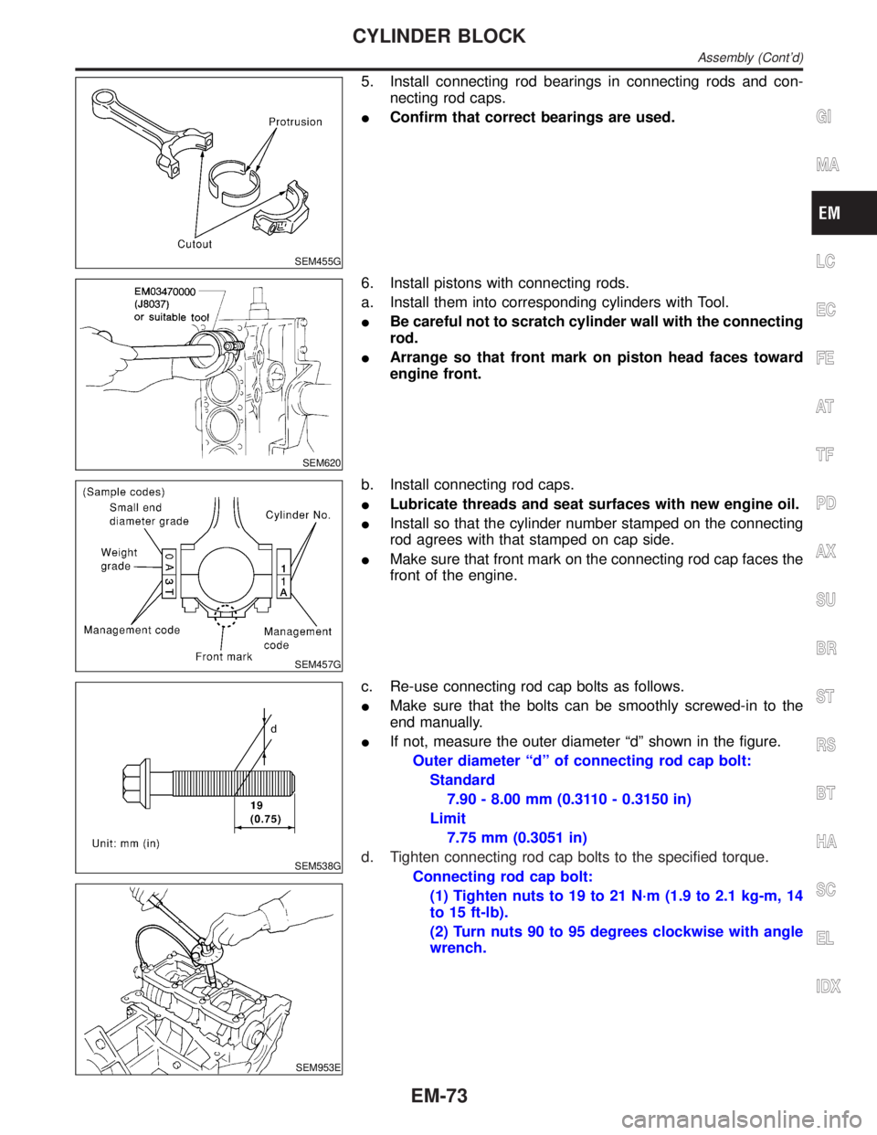
5. Install connecting rod bearings in connecting rods and con-
necting rod caps.
IConfirm that correct bearings are used.
SEM620
6. Install pistons with connecting rods.
a. Install them into corresponding cylinders with Tool.
IBe careful not to scratch cylinder wall with the connecting
rod.
IArrange so that front mark on piston head faces toward
engine front.
SEM457G
b. Install connecting rod caps.
ILubricate threads and seat surfaces with new engine oil.
IInstall so that the cylinder number stamped on the connecting
rod agrees with that stamped on cap side.
IMake sure that front mark on the connecting rod cap faces the
front of the engine.
SEM538G
SEM953E
c. Re-use connecting rod cap bolts as follows.
IMake sure that the bolts can be smoothly screwed-in to the
end manually.
IIf not, measure the outer diameter ªdº shown in the figure.
Outer diameter ªdº of connecting rod cap bolt:
Standard
7.90 - 8.00 mm (0.3110 - 0.3150 in)
Limit
7.75 mm (0.3051 in)
d. Tighten connecting rod cap bolts to the specified torque.
Connecting rod cap bolt:
(1) Tighten nuts to 19 to 21 N´m (1.9 to 2.1 kg-m, 14
to 15 ft-lb).
(2) Turn nuts 90 to 95 degrees clockwise with angle
wrench.
GI
MA
LC
EC
FE
AT
TF
PD
AX
SU
BR
ST
RS
BT
HA
SC
EL
IDX
CYLINDER BLOCK
Assembly (Cont'd)
EM-73
Page 1717 of 2395
SEM954E
7. Measure connecting rod side clearance.
Connecting rod side clearance:
Standard
0.20 - 0.35 mm (0.0079 - 0.0138 in)
Limit
0.40 mm (0.0157 in)
If beyond the limit, replace connecting rod and/or crankshaft.
8. Install rear oil seal retainer.
SEM005G
REPLACEMENT OF PILOT CONVERTERNBEM0028S041. Remove pilot converter using tool or suitable tool.
SEM537E
2. Install pilot converter as shown.
SEM539G
DRIVE PLATENBEM0028S06Install drive plate.
IInstall the drive plate and reinforce plate in the direction shown
in the figure.
ISecure the crankshaft using a ring gear stopper.
ITighten the installation bolts crosswise over several times.
CYLINDER BLOCK
Assembly (Cont'd)
EM-74
Page 1724 of 2395
EM671
Cam height ªAº Intake and exhaust 44.465 - 44.655 (1.7506 - 1.7581)
Wear limit of cam height 0.2 (0.008)
Valve timing
Unit: degree
abcde f
232 230 ±3 53 6 46
Cylinder BlockNBEM0035Unit: mm (in)
SEM022EA
Surface flatnessStandardLess than 0.03 (0.0012)
Limit0.10 (0.0039)
Cylinder bore Inner diameterStandardGrade No. 1 95.500 - 95.510 (3.7598 - 3.7602)
Grade No. 2 95.510 - 95.520 (3.7602 - 3.7606)
Grade No. 3 95.520 - 95.530 (3.7606 - 3.7610)
Wear limit 0.20 (0.0079)
Out-of-round (X þ Y)Less than 0.015 (0.0006)
Taper (AþBþC)Less than 0.015 (0.0006)
GI
MA
LC
EC
FE
AT
TF
PD
AX
SU
BR
ST
RS
BT
HA
SC
EL
IDX
SERVICE DATA AND SPECIFICATIONS (SDS)
Camshaft and Camshaft Bearing (Cont'd)
EM-81
Page 1725 of 2395
Main journal inner
diameter grade
(Without bearing)Grade No. A
Grade No. B
Grade No. C
Grade No. D
Grade No. E
Grade No. F
Grade No. G
Grade No. H
Grade No. J
Grade No. K
Grade No. L
Grade No. M
Grade No. N
Grade No. P
Grade No. R
Grade No. S
Grade No. T
Grade No. U
Grade No. V
Grade No. W
Grade No. X
Grade No. Y
Grade No. 4
Grade No. 763.993 - 63.994 (2.5194 - 2.5194)
63.994 - 63.995 (2.5194 - 2.5195)
63.995 - 63.996 (2.5195 - 2.5195)
63.996 - 63.997 (2.5195 - 2.5196)
63.997 - 63.998 (2.5196 - 2.5196)
63.998 - 63.999 (2.5196 - 2.5196)
63.999 - 64.000 (2.5196 - 2.5197)
64.000 - 64.001 (2.5197 - 2.5197)
64.001 - 64.002 (2.5197 - 2.5198)
64.002 - 64.003 (2.5198 - 2.5198)
64.003 - 64.004 (2.5198 - 2.5198)
64.004 - 64.005 (2.5198 - 2.5199)
64.005 - 64.006 (2.5199 - 2.5199)
64.006 - 64.007 (2.5199 - 2.5200)
64.007 - 64.008 (2.5200 - 2.5200)
64.008 - 64.009 (2.5200 - 2.5200)
64.009 - 64.010 (2.5200 - 2.5201)
64.010 - 64.011 (2.5201 - 2.5201)
64.011 - 64.012 (2.5201 - 2.5202)
64.012 - 64.013 (2.5202 - 2.5202)
64.013 - 64.014 (2.5202 - 2.5202)
64.014 - 64.015 (2.5202 - 2.5203)
64.015 - 64.016 (2.5203 - 2.5203)
64.016 - 64.017 (2.5203 - 2.5203)
Difference in inner
diameter between
cylindersStandardLess than 0.03 (0.0012)
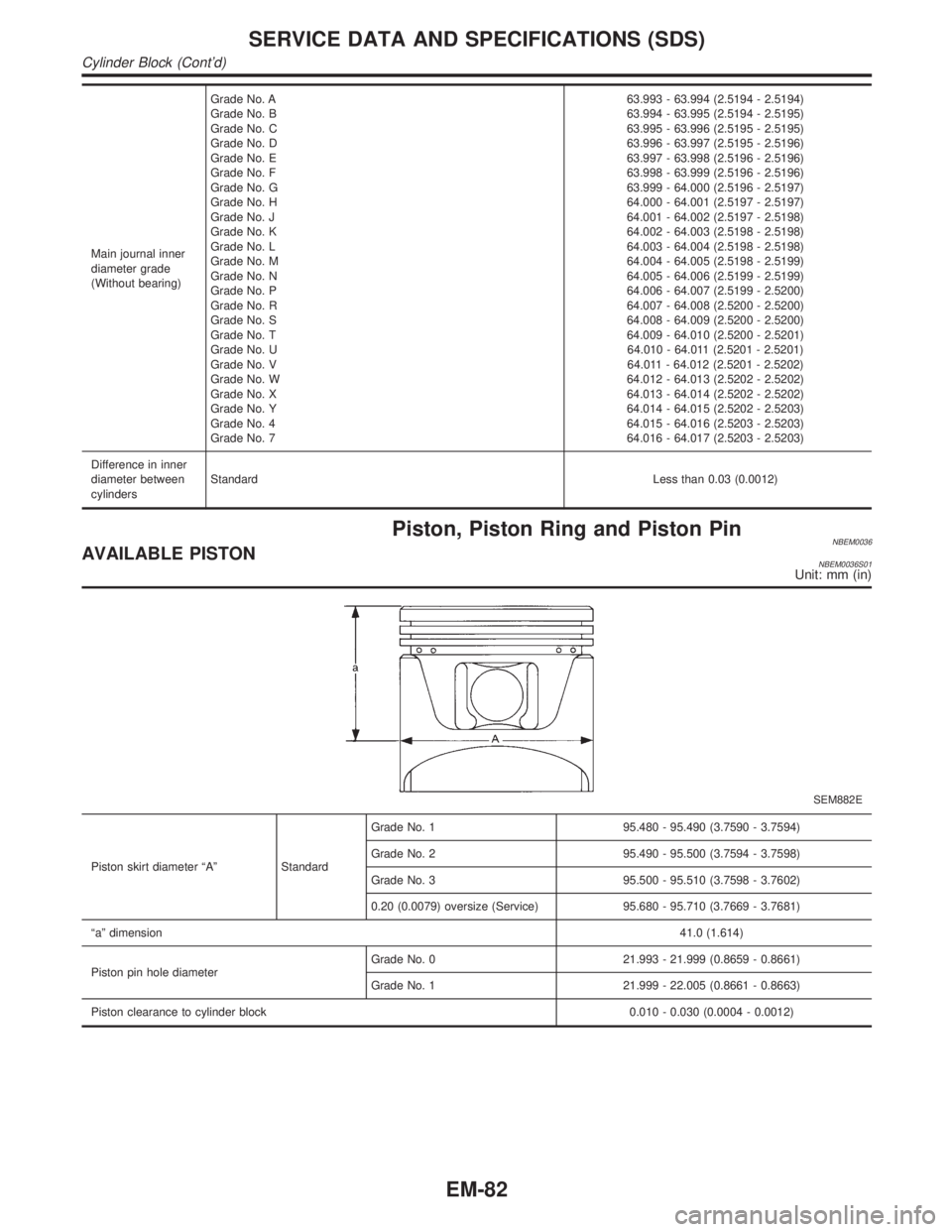
Piston, Piston Ring and Piston PinNBEM0036AVAILABLE PISTONNBEM0036S01Unit: mm (in)
SEM882E
Piston skirt diameter ªAº StandardGrade No. 1 95.480 - 95.490 (3.7590 - 3.7594)
Grade No. 2 95.490 - 95.500 (3.7594 - 3.7598)
Grade No. 3 95.500 - 95.510 (3.7598 - 3.7602)
0.20 (0.0079) oversize (Service) 95.680 - 95.710 (3.7669 - 3.7681)
ªaº dimension41.0 (1.614)
Piston pin hole diameterGrade No. 0 21.993 - 21.999 (0.8659 - 0.8661)
Grade No. 1 21.999 - 22.005 (0.8661 - 0.8663)
Piston clearance to cylinder block 0.010 - 0.030 (0.0004 - 0.0012)
SERVICE DATA AND SPECIFICATIONS (SDS)
Cylinder Block (Cont'd)
EM-82
Page 1732 of 2395
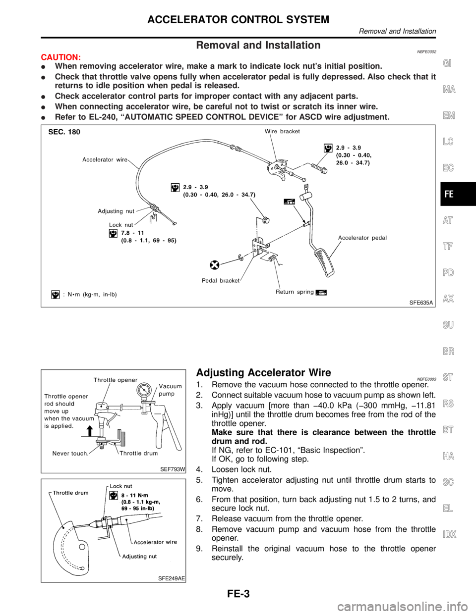
Removal and InstallationNBFE0002CAUTION:
IWhen removing accelerator wire, make a mark to indicate lock nut's initial position.
ICheck that throttle valve opens fully when accelerator pedal is fully depressed. Also check that it
returns to idle position when pedal is released.
ICheck accelerator control parts for improper contact with any adjacent parts.
IWhen connecting accelerator wire, be careful not to twist or scratch its inner wire.
IRefer to EL-240, ªAUTOMATIC SPEED CONTROL DEVICEº for ASCD wire adjustment.
SFE635A
SEF793W
SFE249AE
Adjusting Accelerator WireNBFE00031. Remove the vacuum hose connected to the throttle opener.
2. Connect suitable vacuum hose to vacuum pump as shown left.
3. Apply vacuum [more than þ40.0 kPa (þ300 mmHg, þ11.81
inHg)] until the throttle drum becomes free from the rod of the
throttle opener.
Make sure that there is clearance between the throttle
drum and rod.
If NG, refer to EC-101, ªBasic Inspectionº.
If OK, go to following step.
4. Loosen lock nut.
5. Tighten accelerator adjusting nut until throttle drum starts to
move.
6. From that position, turn back adjusting nut 1.5 to 2 turns, and
secure lock nut.
7. Release vacuum from the throttle opener.
8. Remove vacuum pump and vacuum hose from the throttle
opener.
9. Reinstall the original vacuum hose to the throttle opener
securely.
GI
MA
EM
LC
EC
AT
TF
PD
AX
SU
BR
ST
RS
BT
HA
SC
EL
IDX
ACCELERATOR CONTROL SYSTEM
Removal and Installation
FE-3
Page 1742 of 2395
Terminal ArrangementNBEL0148
MEL069M
FUSE BLOCK Ð JUNCTION BOX (J/B)
Terminal Arrangement
Page 1745 of 2395
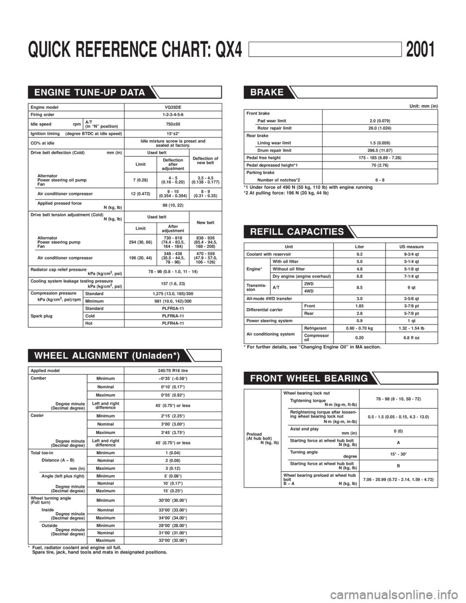
QUICK REFERENCE CHART: QX42001
Engine model VQ35DE
Firing order 1-2-3-4-5-6
Idle speed rpmA/T
(in ªNº position)750 50
Ignition timing (degree BTDC at idle speed) 15É 2É
CO% at idleIdle mixture screw is preset and
sealed at factory.
Drive belt deflection (Cold) mm (in) Used belt
Deflection of
new belt
LimitDeflection
after
adjustment
Alternator
Power steering oil pump
Fan7 (0.28)4-5
(0.16 - 0.20)3.5 - 4.5
(0.138 - 0.177)
Air conditioner compressor 12 (0.472)9-10
(0.354 - 0.394)8-9
(0.31 - 0.35)
Applied pressed force
N (kg, lb)98 (10, 22)
Drive belt tension adjustment (Cold)
N (kg, lb)Used belt
New belt
LimitAfter
adjustment
Alternator
Power steering pump
Fan294 (30, 66)730 - 818
(74.4 - 83.5,
164 - 184)838 - 926
(85.4 - 94.5,
188 - 208)
Air conditioner compressor 196 (20, 44)348 - 436
(35.5 - 44.5,
78 - 98)470 - 559
(47.9 - 57.0,
106 - 126)
Radiator cap relief pressure
kPa (kg/cm
2, psi)78 - 98 (0.8 - 1.0, 11 - 14)
Cooling system leakage testing pressure
kPa (kg/cm
2, psi)157 (1.6, 23)
Compression pressure
kPa (kg/cm
2, psi)/rpmStandard 1,275 (13.0, 185)/300
Minimum 981 (10.0, 142)/300
Spark plugStandard PLFR5A-11
Cold PLFR6A-11
Hot PLFR4A-11
Applied model 245/70 R16 tire
Camber
Degree minute
(Decimal degree)Minimum þ0É35¢(þ0.58É)
Nominal 0É10¢(0.17É)
Maximum 0É55¢(0.92É)
Left and right
difference45¢(0.75É) or less
Caster
Degree minute
(Decimal degree)Minimum 2É15¢(2.25É)
Nominal 3É00¢(3.00É)
Maximum 3É45¢(3.75É)
Left and right
difference45¢(0.75É) or less
Total toe-in Minimum 1 (0.04)
Distance (A þ B)
mm (in)Nominal 2 (0.08)
Maximum 3 (0.12)
Angle (left plus right)
Degree minute
(Decimal degree)Minimum 5¢(0.08É)
Nominal 10¢(0.17É)
Maximum 15¢(0.25É)
Wheel turning angle
(Full turn)Minimum 30É00¢(30.00É)
Inside
Degree minute
(Decimal degree)Nominal 33É00¢(33.00É)
Maximum 34É00¢(34.00É)
Outside
Degree minute
(Decimal degree)Minimum 28É00¢(28.00É)
Nominal 31É00¢(31.00É)
Maximum 32É00¢(32.00É)
* Fuel, radiator coolant and engine oil full.
Spare tire, jack, hand tools and mats in designated positions.
Unit: mm (in)Front brake
Pad wear limit 2.0 (0.079)
Rotor repair limit 26.0 (1.024)
Rear brake
Lining wear limit 1.5 (0.059)
Drum repair limit 296.5 (11.67)
Pedal free height 175 - 185 (6.89 - 7.28)
Pedal depressed height*1 70 (2.76)
Parking brake
Number of notches*2 6 - 8
*1 Under force of 490 N (50 kg, 110 lb) with engine running
*2 At pulling force: 196 N (20 kg, 44 lb)
Unit Liter US measure
Coolant with reservoir 9.2 9-3/4 qt
Engine*With oil filter 5.0 5-1/4 qt
Without oil filter 4.8 5-1/8 qt
Dry engine (engine overhaul) 6.8 7-1/4 qt
Transmis-
sionA/T2WD
8.5 9 qt
4WD
All-mode 4WD transfer 3.0 2-5/8 qt
Differential carrierFront 1.85 3-7/8 pt
Rear 2.8 5-7/8 pt
Power steering system 0.9 1 qt
Air conditioning systemRefrigerant 0.60 - 0.70 kg 1.32 - 1.54 lb
Compressor
oil0.20 6.8 fl oz
* For further details, see ªChanging Engine Oilº in MA section.
Preload
(At hub bolt)
N (kg, lb)Wheel bearing lock nut
78-98(8-10,58-72)
Tightening torque
N×m (kg-m, ft-lb)
Retightening torque after loosen-
ing wheel bearing lock nut
N×m (kg-m, in-lb)0.5 - 1.5 (0.05 - 0.15, 4.3 - 13.0)
Axial end play
mm (in)0 (0)
Starting force at wheel hub bolt
N (kg, lb)A
Turning angle
degree15É - 30É
Starting force at wheel hub bolt
N (kg, lb)B
Wheel bearing preload at wheel hub
bolt
B þ A N (kg, lb)7.06 - 20.99 (0.72 - 2.14, 1.59 - 4.72)