Page 1690 of 2395
SEM867E
Lifter guide bore diameter:
35.000 - 35.021 mm (1.3780 - 1.3788 in)
SEM085D
AssemblyNBEM00201. Install valve component parts.
IAlways use new valve oil seal. Refer to ªVALVE OIL
SEALº, EM-35.
IBefore installing valve oil seal, install valve spring seat.
IInstall valve spring (uneven pitch type) with its narrow
pitch side toward cylinder head side (paint mark).
IAfter installing valve component parts, tap valve stem tip with
plastic hammer to assure a proper fit.
SEM891E
InstallationNBEM00211. Before installing rear timing chain case, remove old liquid gas-
ket from mating surface using a scraper.
IAlso remove old liquid gasket from mating surface of cylinder
block.
SEM161F
IRemove old liquid gasket from the bolt hole and thread.
SEM892E
2. Before installing cam bracket, remove old liquid gasket from
mating surface using a scraper.
GI
MA
LC
EC
FE
AT
TF
PD
AX
SU
BR
ST
RS
BT
HA
SC
EL
IDX
CYLINDER HEAD
Inspection (Cont'd)
EM-47
Page 1692 of 2395
SEM877EA
SEM878EA
SEM879EA
5. Install cylinder head outside bolts.
ITightening procedure:
a.Tighten all bolts to 98 N´m (10 kg-m, 72 ft-lb).
b.Completely loosen all bolts.
c.Tighten all bolts to 34 to 44 N´m (3.5 to 4.5 kg-m, 25 to 33
ft-lb).
d.Turn all bolts 90 to 95 degrees clockwise.
e.Turn all bolts 90 to 95 degrees clockwise.
ITighten in numerical order shown in the figure.
SEM444G
6. Install camshaft chain tensioners on both sides of cylinder
head.
SEM652F
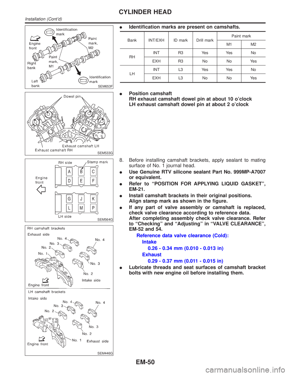
7. Install exhaust and intake camshafts and camshaft brackets.
IIntake camshaft has a drill mark on camshaft sprocket
mounting flange. Install it on the intake side.
GI
MA
LC
EC
FE
AT
TF
PD
AX
SU
BR
ST
RS
BT
HA
SC
EL
IDX
CYLINDER HEAD
Installation (Cont'd)
EM-49
Page 1693 of 2395

SEM653F
IIdentification marks are present on camshafts.
Bank INT/EXH ID mark Drill markPaint mark
M1 M2
RHINT R3 Yes Yes No
EXH R3 No No Yes
LHINT L3 Yes Yes No
EXH L3 No No Yes
SEM533G
IPosition camshaft
RH exhaust camshaft dowel pin at about 10 o'clock
LH exhaust camshaft dowel pin at about 2 o'clock
SEM564G
SEM446G
8. Before installing camshaft brackets, apply sealant to mating
surface of No. 1 journal head.
IUse Genuine RTV silicone sealant Part No. 999MP-A7007
or equivalent.
IRefer to ªPOSITION FOR APPLYING LIQUID GASKETº,
EM-21.
IInstall camshaft brackets in their original positions.
Align stamp mark as shown in the figure.
IIf any part of valve assembly or camshaft is replaced,
check valve clearance according to reference data.
After completing assembly check valve clearance. Refer
to ªCheckingº and ªAdjustingº in ªVALVE CLEARANCEº,
EM-52 and 54.
Reference data valve clearance (Cold):
Intake
0.26 - 0.34 mm (0.010 - 0.013 in)
Exhaust
0.29 - 0.37 mm (0.011 - 0.015 in)
ILubricate threads and seat surfaces of camshaft bracket
bolts with new engine oil before installing them.
CYLINDER HEAD
Installation (Cont'd)
EM-50
Page 1694 of 2395
SEM885EA
SEM886EA
ITighten the camshaft brackets in the following steps.
Step Tightening torque Tightening order
1 1.96 N´m (0.2 kg-m, 17 in-lb)Tighten in the order of 7 to 10,
then tighten 1 to 6.
2 5.88 N´m (0.6 kg-m, 52 in-lb) Tighten in the numerical order.
39.02 - 11.8 N´m (0.92 - 1.20 kg-m,
79.9 - 104.2 in-lb)Tighten in the numerical order.
SEM443G
9. Install CVTC valves.
SEM534G
10. Install O-rings to cylinder block.
SEM447G
11. Install O-rings to cylinder head.
GI
MA
LC
EC
FE
AT
TF
PD
AX
SU
BR
ST
RS
BT
HA
SC
EL
IDX
CYLINDER HEAD
Installation (Cont'd)
EM-51
Page 1695 of 2395

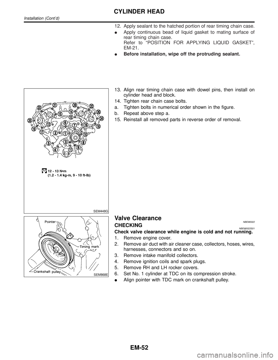
12. Apply sealant to the hatched portion of rear timing chain case.
IApply continuous bead of liquid gasket to mating surface of
rear timing chain case.
Refer to ªPOSITION FOR APPLYING LIQUID GASKETº,
EM-21.
IBefore installation, wipe off the protruding sealant.
SEM448G
13. Align rear timing chain case with dowel pins, then install on
cylinder head and block.
14. Tighten rear chain case bolts.
a. Tighten bolts in numerical order shown in the figure.
b. Repeat above step a.
15. Reinstall all removed parts in reverse order of removal.
SEM868E
Valve ClearanceNBEM0022CHECKINGNBEM0022S01Check valve clearance while engine is cold and not running.
1. Remove engine cover.
2. Remove air duct with air cleaner case, collectors, hoses, wires,
harnesses, connectors and so on.
3. Remove intake manifold collectors.
4. Remove ignition coils and spark plugs.
5. Remove RH and LH rocker covers.
6. Set No. 1 cylinder at TDC on its compression stroke.
IAlign pointer with TDC mark on crankshaft pulley.
CYLINDER HEAD
Installation (Cont'd)
EM-52
Page 1704 of 2395
ComponentsNBEM0024
SEM584G
1. Rear oil seal retainer
2. Cylinder block
3. Knock sensor
4. Upper main bearing
5. Lower main bearing
6. Oil jet
7. Water drain plug (RH side)
8. Water drain plug (Water pump
side)9. Main bearing cap
10. Main bearing beam
11. Crankshaft
12. Pilot converter
13. Drive plate with signal plate
14. Drive plate reinforce plate
15. Oil ring
16. Piston pin17. Connecting rod bearing
18. Connecting rod
19. Piston
20. Top ring
21. 2nd ring
22. Baffle plate
23. Water drain plug (LH side)
GI
MA
LC
EC
FE
AT
TF
PD
AX
SU
BR
ST
RS
BT
HA
SC
EL
IDX
CYLINDER BLOCK
Components
EM-61
Page 1705 of 2395
CYLINDER BLOCK HEATERNBEM0024S02
SEM537G
SEM180FA
Removal and InstallationNBEM0025CAUTION:
IWhen installing bearings, pistons, or other sliding parts,
lubricate contacting surfaces with new engine oil.
IPlace removed parts such as bearings and bearing caps
in their proper order and direction.
IWhen installing connecting rod nuts, and main bearing
cap bolts, apply new engine oil to threads and seating
surfaces.
IDo not allow any magnetic materials to contact the signal
plate teeth of drive plate.
SEM190FA
DisassemblyNBEM0026PISTON, CRANKSHAFT AND OIL JETNBEM0026S011. Remove engine. Refer to ªRemoval and Installationº, EM-57.
2. Place engine on a work stand.
3. Drain coolant and oil.
4. Remove oil pan. Refer to ªRemovalº, EM-15.
5. Remove timing chain. Refer to ªRemovalº, EM-23.
6. Remove cylinder head. Refer to ªRemovalº, EM-23.
CYLINDER BLOCK
Components (Cont'd)
EM-62
Page 1706 of 2395

SEM965A
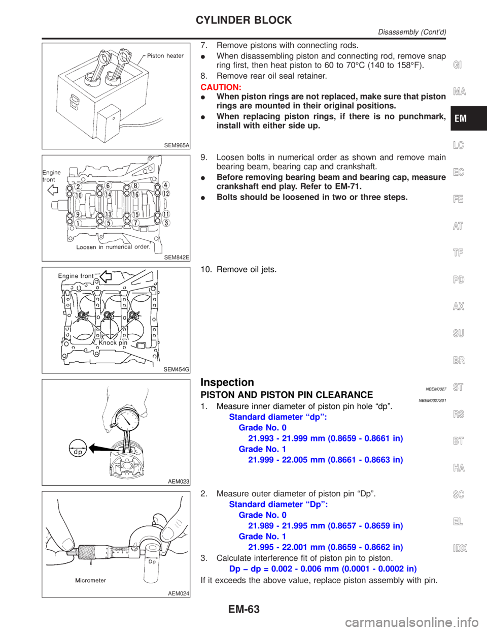
7. Remove pistons with connecting rods.
IWhen disassembling piston and connecting rod, remove snap
ring first, then heat piston to 60 to 70ÉC (140 to 158ÉF).
8. Remove rear oil seal retainer.
CAUTION:
IWhen piston rings are not replaced, make sure that piston
rings are mounted in their original positions.
IWhen replacing piston rings, if there is no punchmark,
install with either side up.
SEM842E
9. Loosen bolts in numerical order as shown and remove main
bearing beam, bearing cap and crankshaft.
IBefore removing bearing beam and bearing cap, measure
crankshaft end play. Refer to EM-71.
IBolts should be loosened in two or three steps.
SEM454G
10. Remove oil jets.
AEM023
InspectionNBEM0027PISTON AND PISTON PIN CLEARANCENBEM0027S011. Measure inner diameter of piston pin hole ªdpº.
Standard diameter ªdpº:
Grade No. 0
21.993 - 21.999 mm (0.8659 - 0.8661 in)
Grade No. 1
21.999 - 22.005 mm (0.8661 - 0.8663 in)
AEM024
2. Measure outer diameter of piston pin ªDpº.
Standard diameter ªDpº:
Grade No. 0
21.989 - 21.995 mm (0.8657 - 0.8659 in)
Grade No. 1
21.995 - 22.001 mm (0.8659 - 0.8662 in)
3. Calculate interference fit of piston pin to piston.
Dp þ dp = 0.002 - 0.006 mm (0.0001 - 0.0002 in)
If it exceeds the above value, replace piston assembly with pin.
GI
MA
LC
EC
FE
AT
TF
PD
AX
SU
BR
ST
RS
BT
HA
SC
EL
IDX
CYLINDER BLOCK
Disassembly (Cont'd)
EM-63