Page 1647 of 2395
Special Service ToolsNBEM0003The actual shapes of Kent-Moore tools may differ from those of special service tools illustrated here.
Tool number
(Kent-Moore No.)
Tool nameDescription
ST0501S000
(Ð)
Engine stand assembly
1 ST05011000
(Ð)
Engine stand
2 ST05012000
(Ð)
Base
NT042
Disassembling and assembling
KV10106500
(Ð)
Engine stand shaft
NT028
KV10117000
(J41262)
Engine sub-attachment
NT373
KV10117000 has been replaced with KV10117001
(KV10117000 is no longer in production, but it is
usable).
KV10117001
(Ð)
Engine sub-attachment
NT372
Installing on the cylinder block
ST10120000
(J24239-01)
Cylinder head bolt
wrench
NT583
Loosening and tightening cylinder head bolt
a: 13 (0.51) dia.
b: 12 (0.47)
c: 10 (0.39)
Unit: mm (in)
KV10116200
(J26336-A)
Valve spring compres-
sor
1 KV10115900
(J26336-20)
Attachment
NT022
Disassembling valve mechanism
PREPARATION
Special Service Tools
EM-4
Page 1652 of 2395

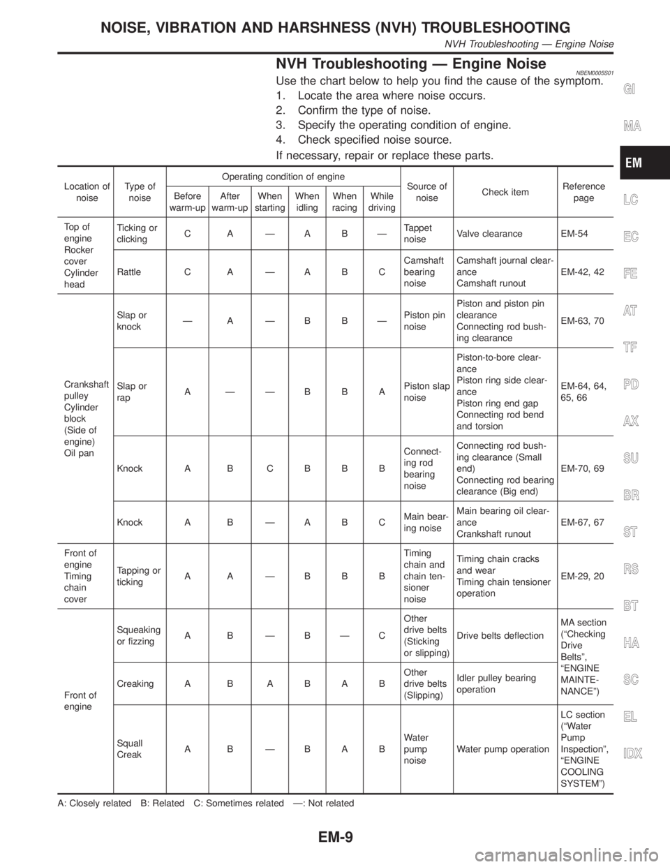
NVH Troubleshooting Ð Engine NoiseNBEM0005S01Use the chart below to help you find the cause of the symptom.
1. Locate the area where noise occurs.
2. Confirm the type of noise.
3. Specify the operating condition of engine.
4. Check specified noise source.
If necessary, repair or replace these parts.
Location of
noiseType of
noiseOperating condition of engine
Source of
noiseCheck itemReference
page Before
warm-upAfter
warm-upWhen
startingWhen
idlingWhen
racingWhile
driving
To p o f
engine
Rocker
cover
Cylinder
headTicking or
clickingC A ÐA BÐTappet
noiseValve clearance EM-54
Rattle C A Ð A B CCamshaft
bearing
noiseCamshaft journal clear-
ance
Camshaft runoutEM-42, 42
Crankshaft
pulley
Cylinder
block
(Side of
engine)
Oil panSlap or
knockÐ A ÐB BÐPiston pin
noisePiston and piston pin
clearance
Connecting rod bush-
ing clearanceEM-63, 70
Slap or
rapA ÐÐBBAPiston slap
noisePiston-to-bore clear-
ance
Piston ring side clear-
ance
Piston ring end gap
Connecting rod bend
and torsionEM-64, 64,
65, 66
Knock A B C B B BConnect-
ing rod
bearing
noiseConnecting rod bush-
ing clearance (Small
end)
Connecting rod bearing
clearance (Big end)EM-70, 69
Knock A B Ð A B CMain bear-
ing noiseMain bearing oil clear-
ance
Crankshaft runoutEM-67, 67
Front of
engine
Timing
chain
coverTapping or
tickingA A ÐBBBTiming
chain and
chain ten-
sioner
noiseTiming chain cracks
and wear
Timing chain tensioner
operationEM-29, 20
Front of
engineSqueaking
or fizzingA B ÐBÐCOther
drive belts
(Sticking
or slipping)Drive belts deflectionMA section
(ªChecking
Drive
Beltsº,
ªENGINE
MAINTE-
NANCEº) Creaking A BABABOther
drive belts
(Slipping)Idler pulley bearing
operation
Squall
CreakA B ÐBABWater
pump
noiseWater pump operationLC section
(ªWater
Pump
Inspectionº,
ªENGINE
COOLING
SYSTEMº)
A: Closely related B: Related C: Sometimes related Ð: Not related
GI
MA
LC
EC
FE
AT
TF
PD
AX
SU
BR
ST
RS
BT
HA
SC
EL
IDX
NOISE, VIBRATION AND HARSHNESS (NVH) TROUBLESHOOTING
NVH Troubleshooting Ð Engine Noise
EM-9
Page 1654 of 2395
SEM484GA
1. Heated oxygen sensor 1 (front)
(bank 1)
2. Heated oxygen sensor 1 (front)
(bank 2)
3. TWC (manifold)4. Thermostat with water inlet
5. Exhaust manifold
6. Thermal transmitter
7. Engine coolant temperature8. Water control valve
9. Water outlet housing
10. Cylinder block water outlet
GI
MA
LC
EC
FE
AT
TF
PD
AX
SU
BR
ST
RS
BT
HA
SC
EL
IDX
OUTER COMPONENT PARTS
Removal and Installation (Cont'd)
EM-11
Page 1660 of 2395
SEM529G
SEM530G
23. Remove front suspension member bolts.
24. Lower the transmission jack carefully to secure clearance
between the oil pan and suspension member.
25. Remove A/T oil cooler tube.
26. Remove water hose and tube.
SEM469G
27. Remove the four engine-to-transmission bolts.
SEM463G
28. Remove aluminum oil pan bolts in numerical order.
SEM365E
29. Remove aluminum oil pan.
a. Insert tool between aluminum oil pan and cylinder block.
IBe careful not to damage aluminum mating surface.
IDo not insert screwdriver, or oil pan flange will be
deformed.
b. Slide tool by tapping its side with a hammer.
GI
MA
LC
EC
FE
AT
TF
PD
AX
SU
BR
ST
RS
BT
HA
SC
EL
IDX
OIL PAN
Removal (Cont'd)
EM-17
Page 1661 of 2395
SEM464G
30. Remove O-rings from cylinder block and oil pump body.
SEM465G
31. Remove front cover gasket and rear oil seal retainer gasket.
SEM466G
InstallationNBEM00101. Before installing oil pan, remove old liquid gasket from mating
surface using a scraper.
IAlso remove old liquid gasket from mating surface of cyl-
inder block.
IRemove old liquid gasket from the bolt hole and thread.
SEM964E
2. Apply sealant to front cover gasket and rear oil seal retainer
gasket.
SEM465G
3. Install front cover gasket and rear oil seal retainer gasket.
OIL PAN
Removal (Cont'd)
EM-18
Page 1662 of 2395
SEM159F
4. Apply a continuous bead of liquid gasket to mating surface of
aluminum oil pan.
IUse Genuine RTV silicone sealant Part No. 999MP-A7007
or equivalent.
SEM467G
5. Apply liquid gasket to inner sealing surface as shown in figure.
IBe sure liquid gasket is 4.0 to 5.0 mm (0.157 to 0.197 in)
or 4.5 to 5.5 mm (0.177 to 0.217 in) wide.
IAttaching should be done within 5 minutes after coating.
SEM464G
6. Install O-rings, cylinder block and oil pump body.
SEM468G
7. Install aluminum oil pan.
ITighten bolts in numerical order.
IWait at least 30 minutes before refilling engine oil.
SEM469G
8. Install the four engine-to-transmission bolts. For tightening
torque, refer to AT-278, ªInstallationº.
9. Reinstall in the revrse order of removal.
GI
MA
LC
EC
FE
AT
TF
PD
AX
SU
BR
ST
RS
BT
HA
SC
EL
IDX
OIL PAN
Installation (Cont'd)
EM-19
Page 1683 of 2395
SEM447G
10. Remove O-rings to cylinder head.
SEM534G
11. Remove O-rings to cylinder block.
SEM443G
12. Remove CVTC valves.
SEM856E
SEM857E
13. Remove intake and exhaust camshafts and camshaft brackets.
IEqually loosen camshaft bracket bolts in several steps in the
numerical order shown in the figure.
For reinstallation, be sure to put marks on camshaft
bracket before removal.
CYLINDER HEAD
Removal (Cont'd)
EM-40
Page 1685 of 2395

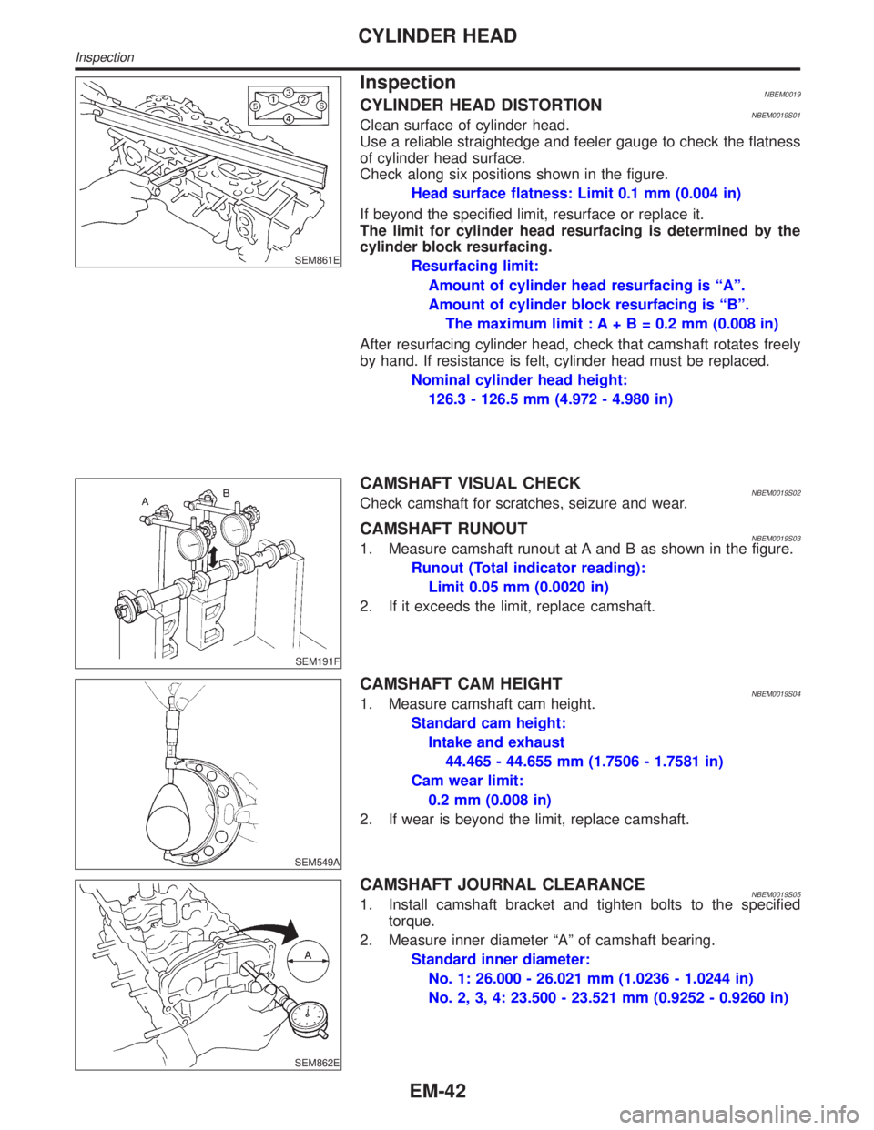
SEM861E
InspectionNBEM0019CYLINDER HEAD DISTORTIONNBEM0019S01Clean surface of cylinder head.
Use a reliable straightedge and feeler gauge to check the flatness
of cylinder head surface.
Check along six positions shown in the figure.
Head surface flatness: Limit 0.1 mm (0.004 in)
If beyond the specified limit, resurface or replace it.
The limit for cylinder head resurfacing is determined by the
cylinder block resurfacing.
Resurfacing limit:
Amount of cylinder head resurfacing is ªAº.
Amount of cylinder block resurfacing is ªBº.
The maximum limit : A+ B = 0.2 mm (0.008 in)
After resurfacing cylinder head, check that camshaft rotates freely
by hand. If resistance is felt, cylinder head must be replaced.
Nominal cylinder head height:
126.3 - 126.5 mm (4.972 - 4.980 in)
SEM191F
CAMSHAFT VISUAL CHECKNBEM0019S02Check camshaft for scratches, seizure and wear.
CAMSHAFT RUNOUTNBEM0019S031. Measure camshaft runout at A and B as shown in the figure.
Runout (Total indicator reading):
Limit 0.05 mm (0.0020 in)
2. If it exceeds the limit, replace camshaft.
SEM549A
CAMSHAFT CAM HEIGHTNBEM0019S041. Measure camshaft cam height.
Standard cam height:
Intake and exhaust
44.465 - 44.655 mm (1.7506 - 1.7581 in)
Cam wear limit:
0.2 mm (0.008 in)
2. If wear is beyond the limit, replace camshaft.
SEM862E
CAMSHAFT JOURNAL CLEARANCENBEM0019S051. Install camshaft bracket and tighten bolts to the specified
torque.
2. Measure inner diameter ªAº of camshaft bearing.
Standard inner diameter:
No. 1: 26.000 - 26.021 mm (1.0236 - 1.0244 in)
No. 2, 3, 4: 23.500 - 23.521 mm (0.9252 - 0.9260 in)
CYLINDER HEAD
Inspection
EM-42