2001 INFINITI QX4 lock
[x] Cancel search: lockPage 1569 of 2395
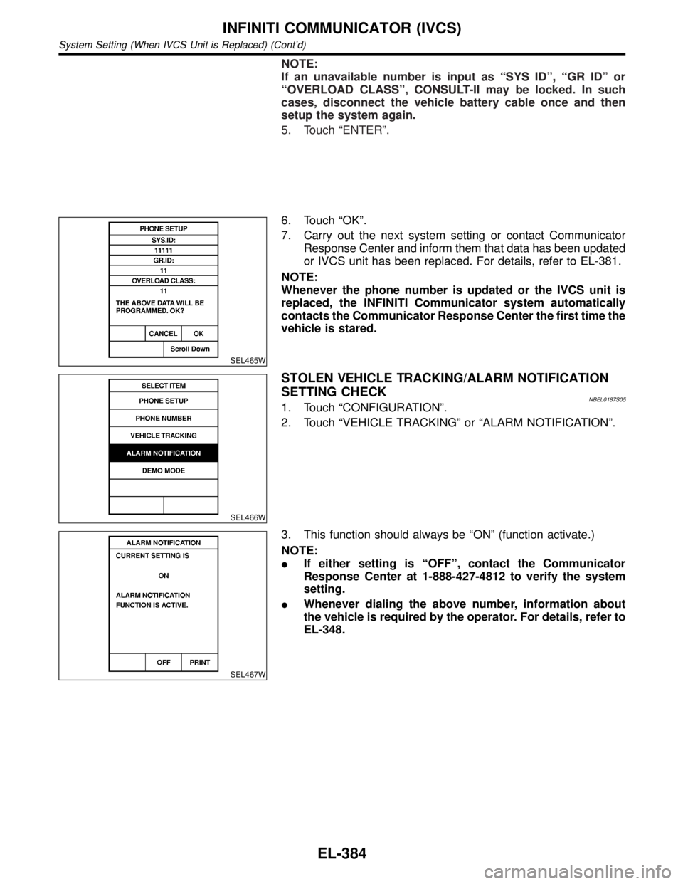
NOTE:
If an unavailable number is input as ªSYS IDº, ªGR IDº or
ªOVERLOAD CLASSº, CONSULT-II may be locked. In such
cases, disconnect the vehicle battery cable once and then
setup the system again.
5. Touch ªENTERº.
SEL465W
6. Touch ªOKº.
7. Carry out the next system setting or contact Communicator
Response Center and inform them that data has been updated
or IVCS unit has been replaced. For details, refer to EL-381.
NOTE:
Whenever the phone number is updated or the IVCS unit is
replaced, the INFINITI Communicator system automatically
contacts the Communicator Response Center the first time the
vehicle is stared.
SEL466W
STOLEN VEHICLE TRACKING/ALARM NOTIFICATION
SETTING CHECK
NBEL0187S051. Touch ªCONFIGURATIONº.
2. Touch ªVEHICLE TRACKINGº or ªALARM NOTIFICATIONº.
SEL467W
3. This function should always be ªONº (function activate.)
NOTE:
IIf either setting is ªOFFº, contact the Communicator
Response Center at 1-888-427-4812 to verify the system
setting.
IWhenever dialing the above number, information about
the vehicle is required by the operator. For details, refer to
EL-348.
INFINITI COMMUNICATOR (IVCS)
System Setting (When IVCS Unit is Replaced) (Cont'd)
EL-384
Page 1573 of 2395
for example, when the vehicle is in a tunnel, in a parking lot
inside building, under an elevated superhighway or near strong
power lines, the location may not be detected. Turbulent/
electric weather conditions may also affect positioning perfor-
mance. If something is placed on the antenna, the radio wave
from GPS satellites may not be received.
SEL688V
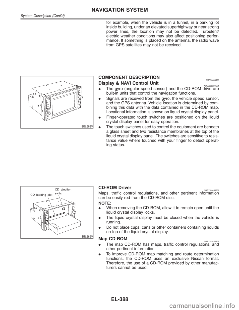
COMPONENT DESCRIPTIONNBEL0228S02Display & NAVI Control UnitNBEL0228S0201IThe gyro (angular speed sensor) and the CD-ROM drive are
built-in units that control the navigation functions.
ISignals are received from the gyro, the vehicle speed sensor,
and the GPS antenna. Vehicle location is determined by com-
bining this data with the data contained in the CD-ROM map.
Locational information is shown on liquid crystal display panel.
IFinger-operated touch switches are positioned on the liquid
crystal display panel for easy operation.
IThe touch switches used to control the equipment are beneath
a glass sheet and two resistance membranes at the top of the
liquid crystal display panel. The switches are sensitive to resis-
tance value where touched with your finger to detect operat-
ing status.
SEL689V
CD-ROM DriverNBEL0228S0202Maps, traffic control regulations, and other pertinent information
can be easily red from the CD-ROM disc.
NOTE:
IWhen removing the CD-ROM, allow it to remain open until the
liquid crystal display locks.
IThe liquid crystal display must be closed when the vehicle is
running.
IDo not place cups, cans or other containers containing liquids
on top of the liquid crystal display.
Map CD-ROMNBEL0228S0203IThe map CD-ROM has maps, traffic control regulations, and
other pertinent information.
ITo improve CD-ROM map matching and route determination
functions, the CD-ROM uses an exclusive Nissan format.
Therefore, the use of a CD-ROM provided by other manufac-
turers cannot be used.
NAVIGATION SYSTEM
System Description (Cont'd)
EL-388
Page 1587 of 2395
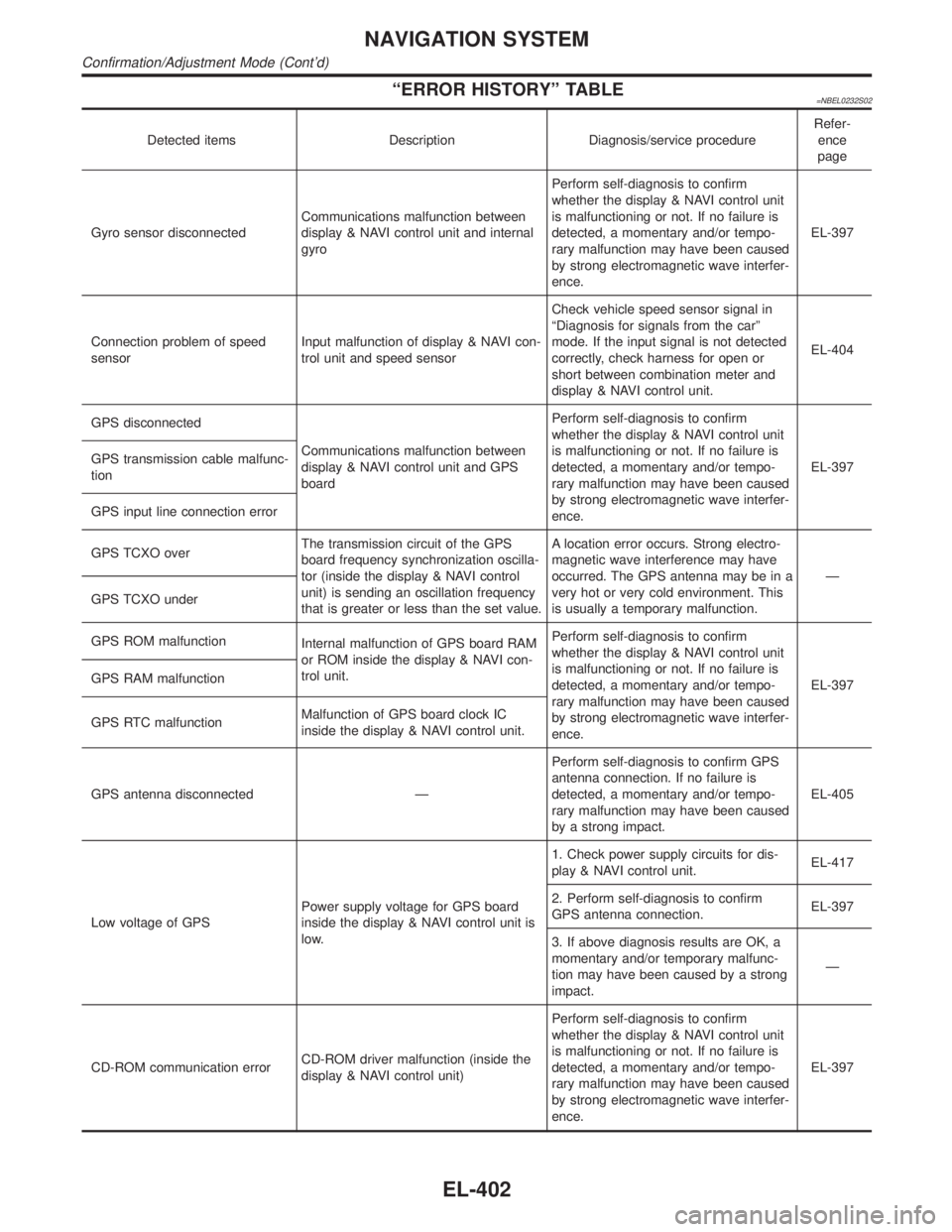
ªERROR HISTORYº TABLE=NBEL0232S02
Detected items Description Diagnosis/service procedureRefer-
ence
page
Gyro sensor disconnectedCommunications malfunction between
display & NAVI control unit and internal
gyroPerform self-diagnosis to confirm
whether the display & NAVI control unit
is malfunctioning or not. If no failure is
detected, a momentary and/or tempo-
rary malfunction may have been caused
by strong electromagnetic wave interfer-
ence.EL-397
Connection problem of speed
sensorInput malfunction of display & NAVI con-
trol unit and speed sensorCheck vehicle speed sensor signal in
ªDiagnosis for signals from the carº
mode. If the input signal is not detected
correctly, check harness for open or
short between combination meter and
display & NAVI control unit.EL-404
GPS disconnected
Communications malfunction between
display & NAVI control unit and GPS
boardPerform self-diagnosis to confirm
whether the display & NAVI control unit
is malfunctioning or not. If no failure is
detected, a momentary and/or tempo-
rary malfunction may have been caused
by strong electromagnetic wave interfer-
ence.EL-397 GPS transmission cable malfunc-
tion
GPS input line connection error
GPS TCXO overThe transmission circuit of the GPS
board frequency synchronization oscilla-
tor (inside the display & NAVI control
unit) is sending an oscillation frequency
that is greater or less than the set value.A location error occurs. Strong electro-
magnetic wave interference may have
occurred. The GPS antenna may be in a
very hot or very cold environment. This
is usually a temporary malfunction.Ð
GPS TCXO under
GPS ROM malfunction
Internal malfunction of GPS board RAM
or ROM inside the display & NAVI con-
trol unit.Perform self-diagnosis to confirm
whether the display & NAVI control unit
is malfunctioning or not. If no failure is
detected, a momentary and/or tempo-
rary malfunction may have been caused
by strong electromagnetic wave interfer-
ence.EL-397 GPS RAM malfunction
GPS RTC malfunctionMalfunction of GPS board clock IC
inside the display & NAVI control unit.
GPS antenna disconnected ÐPerform self-diagnosis to confirm GPS
antenna connection. If no failure is
detected, a momentary and/or tempo-
rary malfunction may have been caused
by a strong impact.EL-405
Low voltage of GPSPower supply voltage for GPS board
inside the display & NAVI control unit is
low.1. Check power supply circuits for dis-
play & NAVI control unit.EL-417
2. Perform self-diagnosis to confirm
GPS antenna connection.EL-397
3. If above diagnosis results are OK, a
momentary and/or temporary malfunc-
tion may have been caused by a strong
impact.Ð
CD-ROM communication errorCD-ROM driver malfunction (inside the
display & NAVI control unit)Perform self-diagnosis to confirm
whether the display & NAVI control unit
is malfunctioning or not. If no failure is
detected, a momentary and/or tempo-
rary malfunction may have been caused
by strong electromagnetic wave interfer-
ence.EL-397
NAVIGATION SYSTEM
Confirmation/Adjustment Mode (Cont'd)
EL-402
Page 1605 of 2395

SEL693VD
POWER SUPPLY AND GROUND CIRCUIT CHECK FOR
DISPLAY & NAVI CONTROL UNIT
=NBEL0234S04Power Supply Circuit CheckNBEL0234S0401
Terminal Ignition switch
(+) (þ) OFF ACC ON
1 Ground Battery voltage Battery voltage Battery voltage
2 Ground Battery voltage Battery voltage Battery voltage
5 Ground 0V 0V Battery voltage
6 Ground 0V Battery voltage Battery voltage
If NG, check the following.
I7.5A fuse [No. 11, located in the fuse block (J/B)]
I10A fuse [No. 10, located in the fuse block (J/B)]
I15A fuse [No. 4, located in the fuse block (J/B)]
IHarness for open or short between fuse and display & NAVI
control unit
SEL694VD
Ground Circuit CheckNBEL0234S0402
Terminals Continuity
3 - Ground Yes
4 - Ground Yes
NAVIGATION SYSTEM
Trouble diagnoses (Cont'd)
EL-420
Page 1642 of 2395
NBEL0145
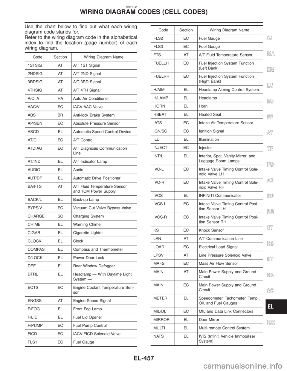
Use the chart below to find out what each wiring
diagram code stands for.
Refer to the wiring diagram code in the alphabetical
index to find the location (page number) of each
wiring diagram.
Code Section Wiring Diagram Name
1STSIG AT A/T 1ST Signal
2NDSIG AT A/T 2ND Signal
3RDSIG AT A/T 3RD Signal
4THSIG AT A/T 4TH Signal
A/C, A HA Auto Air Conditioner
AAC/V EC IACV-AAC Valve
ABS BR Anti-lock Brake System
AP/SEN EC Absolute Pressure Sensor
ASCD EL Automatic Speed Control Device
AT/C EC A/T Control
ATDIAG EC A/T Diagnosis Communication
Line
AT/IND EL A/T Indicator Lamp
AUDIO EL Audio
AUT/DP EL Automatic Drive Positioner
BA/FTS AT A/T Fluid Temperature Sensor
and TCM Power Supply
BACK/L EL Back-up Lamp
BYPS/V EC Vacuum Cut Valve Bypass Valve
CHARGE SC Charging System
CHIME EL Warning Chime
CIGAR EL Cigarette Lighter
CLOCK EL Clock
COMPAS EL Compass and Thermometer
D/LOCK EL Power Door Lock
DEF EL Rear Window Defogger
DTRL EL Headlamp Ð With Daytime Light
System Ð
ECTS EC Engine Coolant Temperature Sen-
sor
ENGSS AT Engine Speed Signal
F/FOG EL Front Fog Lamp
F/LID EL Fuel Lid Opener
F/PUMP EC Fuel Pump Control
FICD EC IACV-FICD Solenoid Valve
FLS1 EC Fuel Gauge
Code Section Wiring Diagram Name
FLS2 EC Fuel Gauge
FLS3 EC Fuel Gauge
FTS AT A/T Fluid Temperature Sensor
FUELLH EC Fuel Injection System Function
(Left Bank)
FUELRH EC Fuel Injection System Function
(Right Bank)
H/AIM EL Headlamp Aiming Control System
H/LAMP EL Headlamp
HORN EL Horn
HSEAT EL Heated Seat
IATS EC Intake Air Temperature Sensor
IGN/SG EC Ignition Signal
ILL EL Illumination
INJECT EC Injector
INT/L EL Interior, Spot, Vanity Mirror, and
Luggage Room Lamps
IVC-L EC Intake Valve Timing Control Sole-
noid Valve LH
IVC-R EC Intake Valve Timing Control Sole-
noid Valve RH
IVCS EL INFINITI Communicator
IVCS-L EC Intake Valve Timing Control Posi-
tion Sensor LH
IVCS-R EC Intake Valve Timing Control Posi-
tion Sensor RH
KS EC Knock Sensor
LAN AT A/T Communication Line
LOAD EC Electrical Load Signal
LPSV AT Line Pressure Solenoid Valve
MAFS EC Mass Air Flow Sensor
MAIN AT Main Power Supply and Ground
Circuit
MAIN EC Main Power Supply and Ground
Circuit
METER EL Speedometer, Tachometer, Temp.,
Oil, and Fuel Gauges
MIL/DL EC MIL and Data Link Connectors
MIRROR EL Door Mirror
MULTI EL Multi-remote Control System
NATS EL IVIS (Infiniti Vehicle Immobiliser
System)
GI
MA
EM
LC
EC
FE
AT
TF
PD
AX
SU
BR
ST
RS
BT
HA
SC
IDX
WIRING DIAGRAM CODES (CELL CODES)
EL-457
Page 1643 of 2395
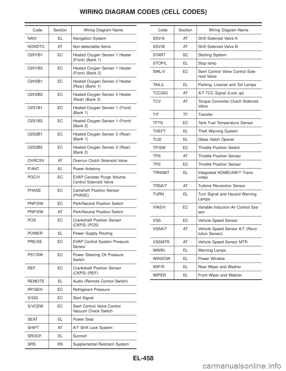
Code Section Wiring Diagram Name
NAVI EL Navigation System
NONDTC AT Non-detectable Items
O2H1B1 EC Heated Oxygen Sensor 1 Heater
(Front) (Bank 1)
O2H1B2 EC Heated Oxygen Sensor 1 Heater
(Front) (Bank 2)
O2H2B1 EC Heated Oxygen Sensor 2 Heater
(Rear) (Bank 1)
O2H2B2 EC Heated Oxygen Sensor 2 Heater
(Rear) (Bank 2)
O2S1B1 EC Heated Oxygen Sensor 1 (Front)
(Bank 1)
O2S1B2 EC Heated Oxygen Sensor 1 (Front)
(Bank 2)
O2S2B1 EC Heated Oxygen Sensor 2 (Rear)
(Bank 1)
O2S2B2 EC Heated Oxygen Sensor 2 (Rear)
(Bank 2)
OVRCSV AT Overrun Clutch Solenoid Valve
P/ANT EL Power Antenna
PGC/V EC EVAP Canister Purge Volume
Control Solenoid Valve
PHASE EC Camshaft Position Sensor
(PHASE)
PNP/SW EC Park/Neutral Position Switch
PNP/SW AT Park/Neutral Position Switch
POS EC Crankshaft Position Sensor
(CKPS) (POS)
POWER EL Power Supply Routing
PRE/SE EC EVAP Control System Pressure
Sensor
PST/SW EC Power Steering Oil Pressure
Switch
REF EC Crankshaft Position Sensor
(CKPS) (REF)
REMOTE EL Audio (Remote Control Switch)
RP/SEN EC Refrigerant Pressure
S/SIG EC Start Signal
S/VCSW EC Swirl Control Valve Control
Vacuum Check Switch
SEAT EL Power Seat
SHIFT AT A/T Shift Lock System
SROOF EL Sunroof
SRS RS Supplemental Restraint SystemCode Section Wiring Diagram Name
SSV/A AT Shift Solenoid Valve A
SSV/B AT Shift Solenoid Valve B
START SC Starting System
STOP/L EL Stop lamp
SWL/V EC Swirl Control Valve Control Sole-
noid Valve
TAIL/L EL Parking, License and Tail Lamps
TCCSIG AT A/T TCC Signal (Lock up)
TCV AT Torque Converter Clutch Solenoid
Valve
T/F TF Transfer
TFTS EC Tank Fuel Temperature Sensor
THEFT EL Theft Warning System
TLID EL Glass Hatch Opener
TP/SW EC Throttle Position Switch
TPS AT Throttle Position Sensor
TPS EC Throttle Position Sensor
TRNSMT EL Integrated HOMELINKYTrans-
mitter
TRSA/T AT Turbine Revolution Sensor
TURN EL Turn Signal and Hazard Warning
Lamps
VIAS/V EC Variable Induction Air Control Sys-
tem
VSS EC Vehicle Speed Sensor
VSSA/T AT Vehicle Speed Sensor A/T (Revo-
lution Sensor)
VSSMTR AT Vehicle Speed Sensor MTR
WARN EL Warning Lamps
WINDOW EL Power Window
WIP/R EL Rear Wiper and Washer
WIPER EL Front Wiper and Washer
WIRING DIAGRAM CODES (CELL CODES)
EL-458
Page 1644 of 2395
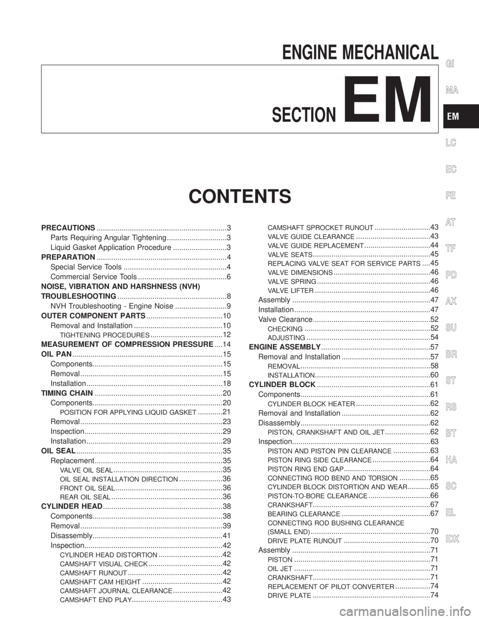
ENGINE MECHANICAL
SECTION
EM
CONTENTS
PRECAUTIONS...............................................................3
Parts Requiring Angular Tightening .............................3
Liquid Gasket Application Procedure ..........................3
PREPARATION...............................................................4
Special Service Tools ..................................................4
Commercial Service Tools ...........................................6
NOISE, VIBRATION AND HARSHNESS (NVH)
TROUBLESHOOTING.....................................................8
NVH Troubleshooting - Engine Noise .........................9
OUTER COMPONENT PARTS.....................................10
Removal and Installation ...........................................10
TIGHTENING PROCEDURES...................................12
MEASUREMENT OF COMPRESSION PRESSURE....14
OIL PAN.........................................................................15
Components...............................................................15
Removal .....................................................................15
Installation ..................................................................18
TIMING CHAIN..............................................................20
Components...............................................................20
POSITION FOR APPLYING LIQUID GASKET............21
Removal .....................................................................23
Inspection...................................................................29
Installation ..................................................................29
OIL SEAL.......................................................................35
Replacement ..............................................................35
VALVE OIL SEAL.....................................................35
OIL SEAL INSTALLATION DIRECTION.....................36
FRONT OIL SEAL....................................................36
REAR OIL SEAL......................................................36
CYLINDER HEAD..........................................................38
Components...............................................................38
Removal .....................................................................39
Disassembly...............................................................41
Inspection...................................................................42
CYLINDER HEAD DISTORTION...............................42
CAMSHAFT VISUAL CHECK....................................42
CAMSHAFT RUNOUT..............................................42
CAMSHAFT CAM HEIGHT.......................................42
CAMSHAFT JOURNAL CLEARANCE........................42
CAMSHAFT END PLAY............................................43
CAMSHAFT SPROCKET RUNOUT...........................43
VALVE GUIDE CLEARANCE....................................43
VALVE GUIDE REPLACEMENT................................44
VALVE SEATS.........................................................45
REPLACING VALVE SEAT FOR SERVICE PARTS....45
VALVE DIMENSIONS...............................................46
VALVE SPRING.......................................................46
VALVE LIFTER........................................................46
Assembly ...................................................................47
Installation ..................................................................47
Valve Clearance.........................................................52
CHECKING.............................................................52
ADJUSTING............................................................54
ENGINE ASSEMBLY.....................................................57
Removal and Installation ...........................................57
REMOVAL...............................................................58
INSTALLATION........................................................60
CYLINDER BLOCK.......................................................61
Components...............................................................61
CYLINDER BLOCK HEATER....................................62
Removal and Installation ...........................................62
Disassembly...............................................................62
PISTON, CRANKSHAFT AND OIL JET......................62
Inspection...................................................................63
PISTON AND PISTON PIN CLEARANCE..................63
PISTON RING SIDE CLEARANCE............................64
PISTON RING END GAP..........................................64
CONNECTING ROD BEND AND TORSION...............65
CYLINDER BLOCK DISTORTION AND WEAR...........65
PISTON-TO-BORE CLEARANCE..............................66
CRANKSHAFT.........................................................67
BEARING CLEARANCE...........................................67
CONNECTING ROD BUSHING CLEARANCE
(SMALL END)
..........................................................70
DRIVE PLATE RUNOUT..........................................70
Assembly ...................................................................71
PISTON..................................................................71
OIL JET..................................................................71
CRANKSHAFT.........................................................71
REPLACEMENT OF PILOT CONVERTER.................74
DRIVE PLATE.........................................................74
GI
MA
LC
EC
FE
AT
TF
PD
AX
SU
BR
ST
RS
BT
HA
SC
EL
IDX
Page 1645 of 2395
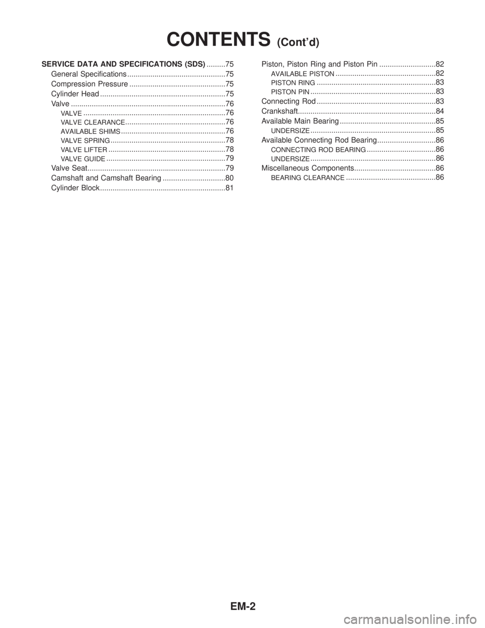
SERVICE DATA AND SPECIFICATIONS (SDS).........75
General Specifications ...............................................75
Compression Pressure ..............................................75
Cylinder Head ............................................................75
Valve ..........................................................................76
VALVE....................................................................76
VALVE CLEARANCE................................................76
AVAILABLE SHIMS..................................................76
VALVE SPRING.......................................................78
VALVE LIFTER........................................................78
VALVE GUIDE.........................................................79
Valve Seat..................................................................79
Camshaft and Camshaft Bearing ..............................80
Cylinder Block ............................................................81Piston, Piston Ring and Piston Pin ...........................82
AVAILABLE PISTON................................................82
PISTON RING.........................................................83
PISTON PIN............................................................83
Connecting Rod .........................................................83
Crankshaft..................................................................84
Available Main Bearing ..............................................85
UNDERSIZE............................................................85
Available Connecting Rod Bearing............................86
CONNECTING ROD BEARING.................................86
UNDERSIZE............................................................86
Miscellaneous Components.......................................86
BEARING CLEARANCE...........................................86
CONTENTS(Cont'd)
EM-2