2001 INFINITI QX4 antenna rod replacement
[x] Cancel search: antenna rod replacementPage 1187 of 2395

Electrical Components Inspection ...........................108
COMPASS AND THERMOMETER............................. 110
System Description .................................................. 110
Wiring Diagram - COMPAS -................................... 111
Trouble Diagnoses................................................... 112
Calibration Procedure for Compass ........................ 113
WARNING LAMPS...................................................... 114
Schematic ................................................................ 114
Wiring Diagram - WARN - ....................................... 115
Fuel Warning Lamp Sensor Check .........................122
Electrical Components Inspection ...........................122
A/T INDICATOR...........................................................123
Wiring Diagram - AT/IND -.......................................123
WARNING CHIME.......................................................125
Component Parts and Harness Connector
Location ...................................................................125
System Description ..................................................125
Wiring Diagram - CHIME - ......................................127
Trouble Diagnoses...................................................129
FRONT WIPER AND WASHER..................................136
System Description ..................................................136
Wiring Diagram - WIPER - ......................................138
Removal and Installation .........................................139
Washer Nozzle Adjustment .....................................140
Washer Tube Layout ...............................................140
REAR WIPER AND WASHER....................................141
System Description ..................................................141
Wiring Diagram - WIP/R -........................................143
Trouble Diagnoses...................................................145
Removal and Installation .........................................145
Washer Nozzle Adjustment .....................................146
Washer Tube Layout ...............................................146
Check Valve .............................................................146
HORN...........................................................................147
Wiring Diagram - HORN - .......................................147
CIGARETTE LIGHTER................................................148
Wiring Diagram - CIGAR -.......................................148
CLOCK.........................................................................150
Wiring Diagram - CLOCK -......................................150
REAR WINDOW DEFOGGER.....................................151
Component Parts and Harness Connector
Location ...................................................................151
System Description ..................................................151
Wiring Diagram - DEF - ...........................................153
Trouble Diagnoses...................................................155
Electrical Components Inspection ...........................157
Filament Check ........................................................157
Filament Repair .......................................................158
AUDIO..........................................................................160
System Description ..................................................160
Schematic ................................................................161
Wiring Diagram - AUDIO - .......................................162Trouble Diagnoses...................................................166
Inspection.................................................................167
Wiring Diagram - REMOTE -...................................168
AUDIO ANTENNA.......................................................169
System Description ..................................................169
Wiring Diagram - P/ANT - .......................................170
Trouble Diagnoses...................................................171
Location of Antenna .................................................171
Antenna Rod Replacement .....................................171
POWER SUNROOF.....................................................173
System Description ..................................................173
Wiring Diagram - SROOF - .....................................174
Trouble Diagnoses...................................................176
DOOR MIRROR...........................................................177
Wiring Diagram - MIRROR - ...................................177
GLASS HATCH OPENER...........................................178
System Description ..................................................178
Wiring Diagram - TLID - ..........................................179
FUEL FILLER LID OPENER.......................................180
Wiring Diagram - F/LID - .........................................180
POWER SEAT.............................................................181
Wiring Diagram - SEAT - .........................................181
HEATED SEAT............................................................183
Wiring Diagram - HSEAT - ......................................183
Seatback Heating Unit .............................................185
AUTOMATIC DRIVE POSITIONER............................186
Component Parts and Harness Connector
Location ...................................................................186
System Description ..................................................187
Schematic ................................................................190
Wiring Diagram - AUT/DP - .....................................191
On Board Diagnosis ................................................196
Trouble Diagnoses...................................................198
AUTOMATIC SPEED CONTROL DEVICE (ASCD)...221
Component Parts and Harness Connector
Location ...................................................................221
System Description ..................................................222
Schematic ................................................................224
Wiring Diagram - ASCD - ........................................225
Fail-safe System ......................................................229
Trouble Diagnoses...................................................230
Electrical Component Inspection .............................239
ASCD Wire Adjustment ...........................................240
POWER WINDOW.......................................................241
System Description ..................................................241
Schematic ................................................................244
Wiring Diagram - WINDOW - ..................................245
Trouble Diagnoses...................................................250
POWER DOOR LOCK.................................................254
Component Parts and Harness Connector
Location ...................................................................254
System Description ..................................................254
CONTENTS(Cont'd)
EL-2
Page 1356 of 2395

Trouble DiagnosesNBEL0086POWER ANTENNANBEL0086S01
Symptom Possible causes Repair order
Power antenna does not
operate.1. 7.5A fuse
2. Audio unit signal
3. Grounds M4, M66 and M1471. Check 7.5A fuse [No. 24, located in fuse block (J/B)].
Verify that battery positive voltage is present at termi-
nal 6 of power antenna.
2. Turn ignition switch and audio unit ON. Verify that
battery positive voltage is present at terminal 4 of
power antenna.
3. Check grounds M4, M66 and M147.
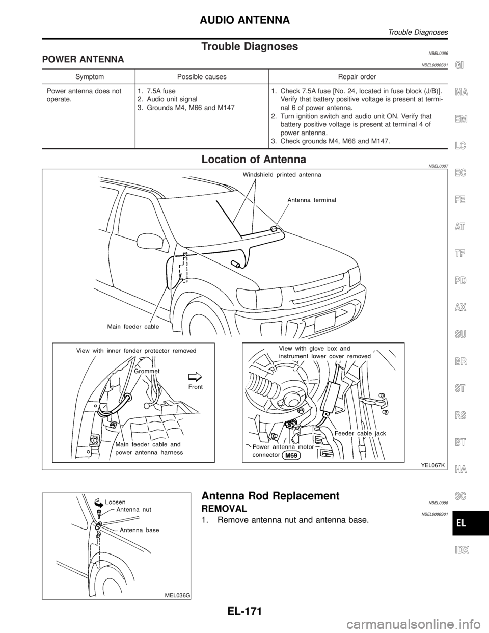
Location of AntennaNBEL0087
YEL067K
MEL036G
Antenna Rod ReplacementNBEL0088REMOVALNBEL0088S011. Remove antenna nut and antenna base.
GI
MA
EM
LC
EC
FE
AT
TF
PD
AX
SU
BR
ST
RS
BT
HA
SC
IDX
AUDIO ANTENNA
Trouble Diagnoses
EL-171
Page 1357 of 2395

MEL037G
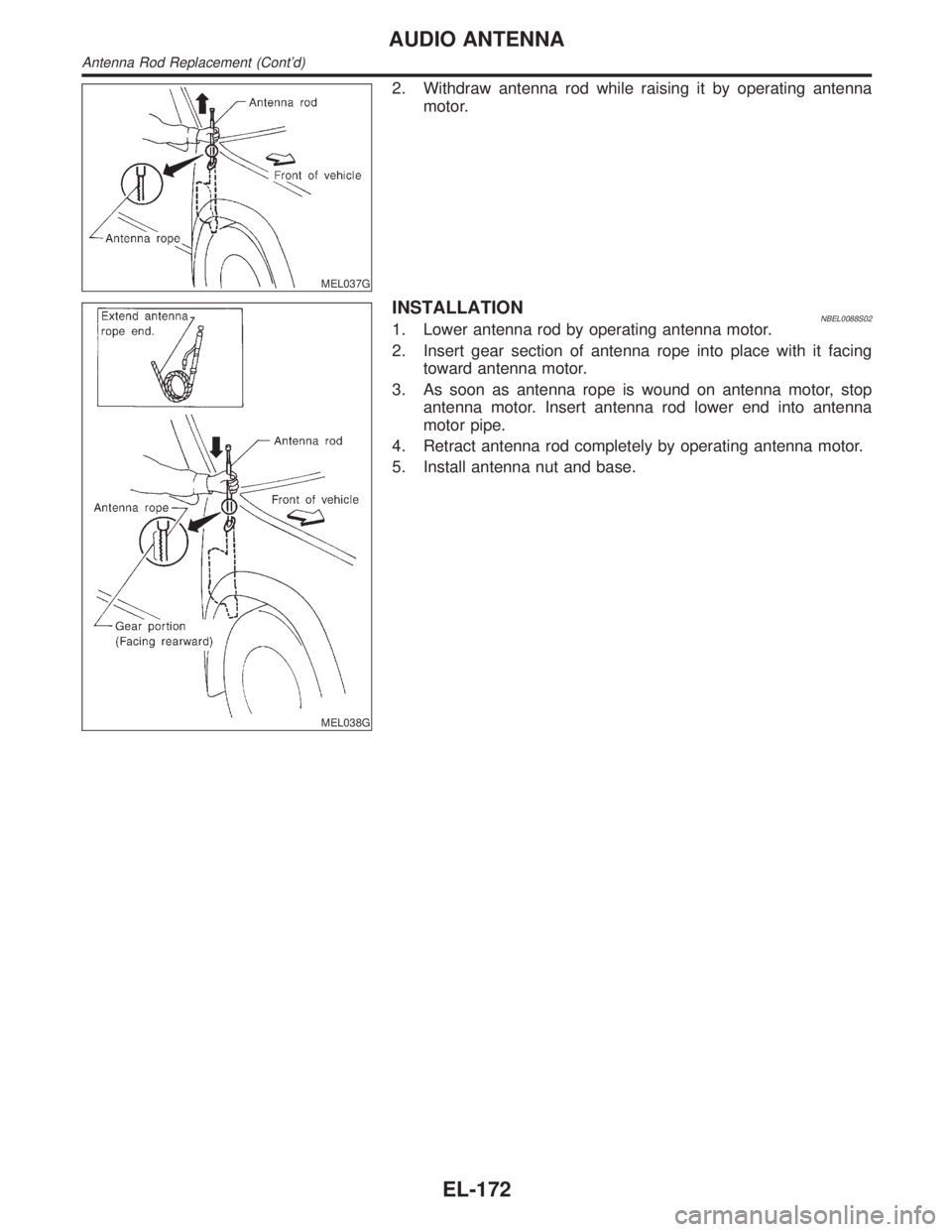
2. Withdraw antenna rod while raising it by operating antenna
motor.
MEL038G
INSTALLATIONNBEL0088S021. Lower antenna rod by operating antenna motor.
2. Insert gear section of antenna rope into place with it facing
toward antenna motor.
3. As soon as antenna rope is wound on antenna motor, stop
antenna motor. Insert antenna rod lower end into antenna
motor pipe.
4. Retract antenna rod completely by operating antenna motor.
5. Install antenna nut and base.
AUDIO ANTENNA
Antenna Rod Replacement (Cont'd)
EL-172