2001 INFINITI QX4 washer fluid
[x] Cancel search: washer fluidPage 8 of 2395

19. A/T Does Not Shift: 22-> 11, When Selector
Lever²2²->²1²Position .........................................255
20. Vehicle Does Not Decelerate By Engine
Brake........................................................................256
21. TCM Self-diagnosis Does Not Activate (PNP,
Overdrive Control and Throttle Position Switches
Circuit Checks) ........................................................257
A/T SHIFT LOCK SYSTEM.........................................265
Description ...............................................................265
Wiring Diagram - SHIFT -........................................266
Diagnostic Procedure ..............................................267
KEY INTERLOCK CABLE..........................................271
Components.............................................................271
Removal ...................................................................271
Installation ................................................................272
ON-VEHICLE SERVICE..............................................273
Control Valve Assembly and Accumulators .............273
Revolution Sensor Replacement .............................274
Turbine Revolution Sensor Replacement................274
Rear Oil Seal Replacement .....................................274
Rear Oil Seal and Companion Flange Oil Seal
Replacement ............................................................275
Parking Components Inspection..............................275
Park/Neutral Position Switch Adjustment ................276
Manual Control Linkage Adjustment........................276
REMOVAL AND INSTALLATION...............................277
Removal ...................................................................277
Installation ................................................................278
OVERHAUL.................................................................281
Components.............................................................281
Oil Channel ..............................................................284
Locations of Needle Bearings, Thrust Washers
and Snap Rings .......................................................285
DISASSEMBLY............................................................286
REPAIR FOR COMPONENT PARTS.........................297Oil Pump ..................................................................297
Control Valve Assembly ...........................................301
Control Valve Upper Body .......................................307
Control Valve Lower Body .......................................312
Reverse Clutch ........................................................314
High Clutch ..............................................................317
Forward and Overrun Clutches ...............................320
Low & Reverse Brake..............................................324
Forward Clutch Drum Assembly ..............................328
Rear Internal Gear and Forward Clutch Hub ..........330
Band Servo Piston Assembly ..................................333
Parking Pawl Components ......................................337
ASSEMBLY..................................................................339
Assembly (1) ............................................................339
Adjustment ...............................................................347
Assembly (2) ............................................................349
SERVICE DATA AND SPECIFICATIONS (SDS).......356
General Specifications .............................................356
Shift Schedule..........................................................356
Stall Revolution ........................................................356
Line Pressure...........................................................356
Return Springs .........................................................357
Accumulator O-ring ..................................................358
Clutches and Brakes ...............................................358
Oil Pump and Low One-way Clutch ........................360
Total End Play..........................................................360
Reverse Clutch Drum End Play ..............................361
Removal and Installation .........................................361
Shift Solenoid Valves ...............................................361
Solenoid Valves .......................................................361
A/T Fluid Temperature Sensor.................................361
Turbine Revolution Sensor ......................................361
Revolution Sensor ...................................................362
Dropping Resistor ....................................................362GI
MA
EM
LC
EC
FE
TF
PD
AX
SU
BR
ST
RS
BT
HA
SC
EL
IDX
CONTENTS(Cont'd)
AT-3
Page 13 of 2395

IBefore assembly, apply a coat of recommended ATF to all
parts. Apply petroleum jelly to protect O-rings and seals, or
hold bearings and washers in place during assembly. Do not
use grease.
IExtreme care should be taken to avoid damage to O-rings,
seals and gaskets when assembling.
IReplace ATF cooler if excessive foreign material is found in oil
pan or clogging strainer. Refer to ªATF COOLER SERVICEº,
AT-9.
IAfter overhaul, refill the transmission with new ATF.
IWhen the A/T drain plug is removed, only some of the fluid is
drained. Old A/T fluid will remain in torque converter and ATF
cooling system.
Always follow the procedures when changing A/T fluid. Refer
to MA-21, ªChanging A/T Fluidº.
Service Notice or PrecautionsNBAT0004FAIL-SAFENBAT0004S01The TCM has an electronic Fail-Safe (limp home mode). This allows the vehicle to be driven even if a major
electrical input/output device circuit is damaged.
Under Fail-Safe, the vehicle always runs in third gear, even with a shift lever position of ª1º, ª2º or ªDº. The
customer may complain of sluggish or poor acceleration.
When the ignition key is turned ªONº following Fail-Safe operation, O/D OFF indicator lamp blinks for about
8 seconds. (For ªTCM SELF-DIAGNOSTIC PROCEDURE (No Tools)º, refer to AT-46.)
Fail-Safe may occur without electrical circuit damage if the vehicle is driven under extreme conditions (such
as excessive wheel spin followed by sudden braking). To recover normal shift pattern, turn the ignition key
ªOFFº for 5 seconds, then ªONº.
The blinking of the O/D OFF indicator lamp for about 8 seconds will appear only once and be cleared. The
customer may resume normal driving conditions.
Always follow the ªWORK FLOWº (Refer to AT-57).
The SELF-DIAGNOSIS results will be as follows:
The first SELF-DIAGNOSIS will indicate damage to the vehicle speed sensor or the revolution sensor.
During the next SELF-DIAGNOSIS, performed after checking the sensor, no damages will be indicated.
TORQUE CONVERTER SERVICENBAT0004S04The torque converter should be replaced under any of the following conditions:
IExternal leaks in the hub weld area.
IConverter hub is scored or damaged.
IConverter pilot is broken, damaged or fits poorly into crankshaft.
ISteel particles are found after flushing the cooler and cooler lines.
IPump is damaged or steel particles are found in the converter.
IVehicle has TCC shudder and/or no TCC apply. Replace only after all hydraulic and electrical diagnoses
have been made. (Converter clutch material may be glazed.)
IConverter is contaminated with engine coolant containing antifreeze.
IInternal failure of stator roller clutch.
IHeavy clutch debris due to overheating (blue converter).
ISteel particles or clutch lining material found in fluid filter or on magnet when no internal parts in unit are
worn or damaged Ð indicates that lining material came from converter.
The torque converter should not be replaced if:
IThe fluid has an odor, is discolored, and there is no evidence of metal or clutch facing particles.
PRECAUTIONS
Precautions (Cont'd)
AT-8
Page 366 of 2395
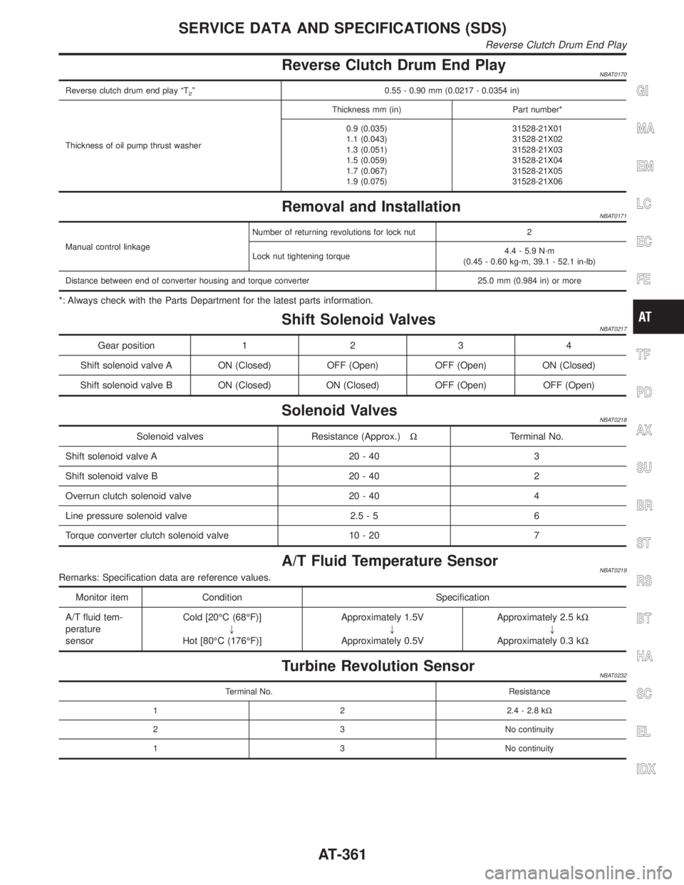
Reverse Clutch Drum End PlayNBAT0170
Reverse clutch drum end play ªT2º 0.55 - 0.90 mm (0.0217 - 0.0354 in)
Thickness of oil pump thrust washerThickness mm (in) Part number*
0.9 (0.035)
1.1 (0.043)
1.3 (0.051)
1.5 (0.059)
1.7 (0.067)
1.9 (0.075)31528-21X01
31528-21X02
31528-21X03
31528-21X04
31528-21X05
31528-21X06
Removal and InstallationNBAT0171
Manual control linkageNumber of returning revolutions for lock nut 2
Lock nut tightening torque4.4 - 5.9 N´m
(0.45 - 0.60 kg-m, 39.1 - 52.1 in-lb)
Distance between end of converter housing and torque converter 25.0 mm (0.984 in) or more
*: Always check with the Parts Department for the latest parts information.
Shift Solenoid ValvesNBAT0217
Gear position1234
Shift solenoid valve A ON (Closed) OFF (Open) OFF (Open) ON (Closed)
Shift solenoid valve B ON (Closed) ON (Closed) OFF (Open) OFF (Open)
Solenoid ValvesNBAT0218
Solenoid valves Resistance (Approx.)WTerminal No.
Shift solenoid valve A 20 - 40 3
Shift solenoid valve B 20 - 40 2
Overrun clutch solenoid valve 20 - 40 4
Line pressure solenoid valve 2.5 - 5 6
Torque converter clutch solenoid valve 10 - 20 7
A/T Fluid Temperature SensorNBAT0219Remarks: Specification data are reference values.
Monitor item Condition Specification
A/T fluid tem-
perature
sensorCold [20ÉC (68ÉF)]
"
Hot [80ÉC (176ÉF)]Approximately 1.5V
"
Approximately 0.5VApproximately 2.5 kW
"
Approximately 0.3 kW
Turbine Revolution SensorNBAT0232
Terminal No. Resistance
1 2 2.4 - 2.8 kW
2 3 No continuity
1 3 No continuity
GI
MA
EM
LC
EC
FE
TF
PD
AX
SU
BR
ST
RS
BT
HA
SC
EL
IDX
SERVICE DATA AND SPECIFICATIONS (SDS)
Reverse Clutch Drum End Play
AT-361
Page 411 of 2395
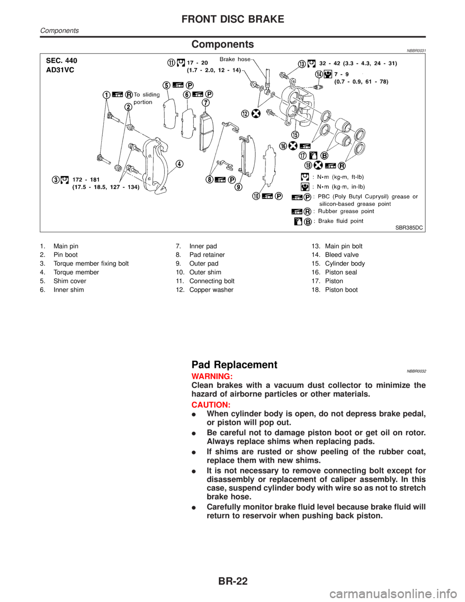
ComponentsNBBR0031
SBR385DC
1. Main pin
2. Pin boot
3. Torque member fixing bolt
4. Torque member
5. Shim cover
6. Inner shim7. Inner pad
8. Pad retainer
9. Outer pad
10. Outer shim
11. Connecting bolt
12. Copper washer13. Main pin bolt
14. Bleed valve
15. Cylinder body
16. Piston seal
17. Piston
18. Piston boot
Pad ReplacementNBBR0032WARNING:
Clean brakes with a vacuum dust collector to minimize the
hazard of airborne particles or other materials.
CAUTION:
IWhen cylinder body is open, do not depress brake pedal,
or piston will pop out.
IBe careful not to damage piston boot or get oil on rotor.
Always replace shims when replacing pads.
IIf shims are rusted or show peeling of the rubber coat,
replace them with new shims.
IIt is not necessary to remove connecting bolt except for
disassembly or replacement of caliper assembly. In this
case, suspend cylinder body with wire so as not to stretch
brake hose.
ICarefully monitor brake fluid level because brake fluid will
return to reservoir when pushing back piston.
FRONT DISC BRAKE
Components
BR-22
Page 1324 of 2395
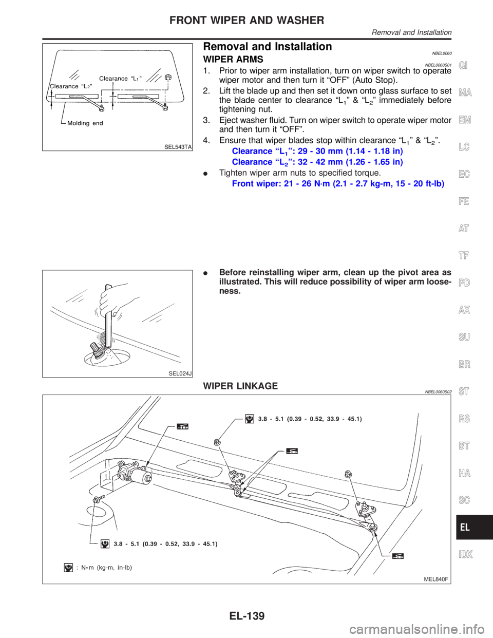
SEL543TA
Removal and InstallationNBEL0060WIPER ARMSNBEL0060S011. Prior to wiper arm installation, turn on wiper switch to operate
wiper motor and then turn it ªOFFº (Auto Stop).
2. Lift the blade up and then set it down onto glass surface to set
the blade center to clearance ªL
1º&ªL2º immediately before
tightening nut.
3. Eject washer fluid. Turn on wiper switch to operate wiper motor
and then turn it ªOFFº.
4. Ensure that wiper blades stop within clearance ªL
1º&ªL2º.
Clearance ªL
1º: 29 - 30 mm (1.14 - 1.18 in)
Clearance ªL
2º: 32 - 42 mm (1.26 - 1.65 in)
ITighten wiper arm nuts to specified torque.
Front wiper: 21 - 26 N´m (2.1 - 2.7 kg-m, 15 - 20 ft-lb)
SEL024J
IBefore reinstalling wiper arm, clean up the pivot area as
illustrated. This will reduce possibility of wiper arm loose-
ness.
WIPER LINKAGENBEL0060S02
MEL840F
GI
MA
EM
LC
EC
FE
AT
TF
PD
AX
SU
BR
ST
RS
BT
HA
SC
IDX
FRONT WIPER AND WASHER
Removal and Installation
EL-139
Page 1331 of 2395
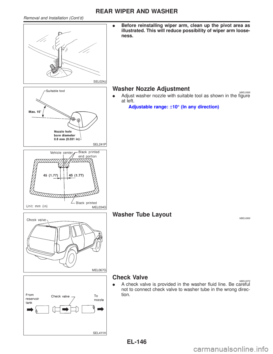
SEL024J
IBefore reinstalling wiper arm, clean up the pivot area as
illustrated. This will reduce possibility of wiper arm loose-
ness.
SEL241P
MEL034G
Washer Nozzle AdjustmentNBEL0068IAdjust washer nozzle with suitable tool as shown in the figure
at left.
Adjustable range:±10É (In any direction)
MEL067G
Washer Tube LayoutNBEL0069
SEL411H
Check ValveNBEL0070IA check valve is provided in the washer fluid line. Be careful
not to connect check valve to washer tube in the wrong direc-
tion.
REAR WIPER AND WASHER
Removal and Installation (Cont'd)
EL-146
Page 1751 of 2395
IClean all disassembled parts in the designated liquid or solvent
prior to inspection or assembly.
IReplace oil seals, gaskets, packings, O-rings, locking washers,
cotter pins, self-locking nuts, etc. with new ones.
IReplace inner and outer races of tapered roller bearings and
needle bearings as a set.
IArrange the disassembled parts in accordance with their
assembled locations and sequence.
IDo not touch the terminals of electrical components which use
microcomputers (such as ECMs).
Static electricity may damage internal electronic components.
IAfter disconnecting vacuum or air hoses, attach a tag to indi-
cate the proper connection.
IUse only the fluids and lubricants specified in this manual.
IUse approved bonding agent, sealants or their equivalents
when required.
IUse tools and recommended special tools where specified for
safe and efficient service repairs.
IWhen repairing the fuel, oil, water, vacuum or exhaust
systems, check all affected lines for leaks.
IDispose of drained oil or the solvent used for cleaning parts in
an appropriate manner.
WARNING:
To prevent ECM from storing the diagnostic trouble codes, do
not carelessly disconnect the harness connectors which are
related to the engine control system and TCM (Transmission
Control Module) system. The connectors should be discon-
nected only when working according to the WORK FLOW of
TROUBLE DIAGNOSES in EC and AT sections.
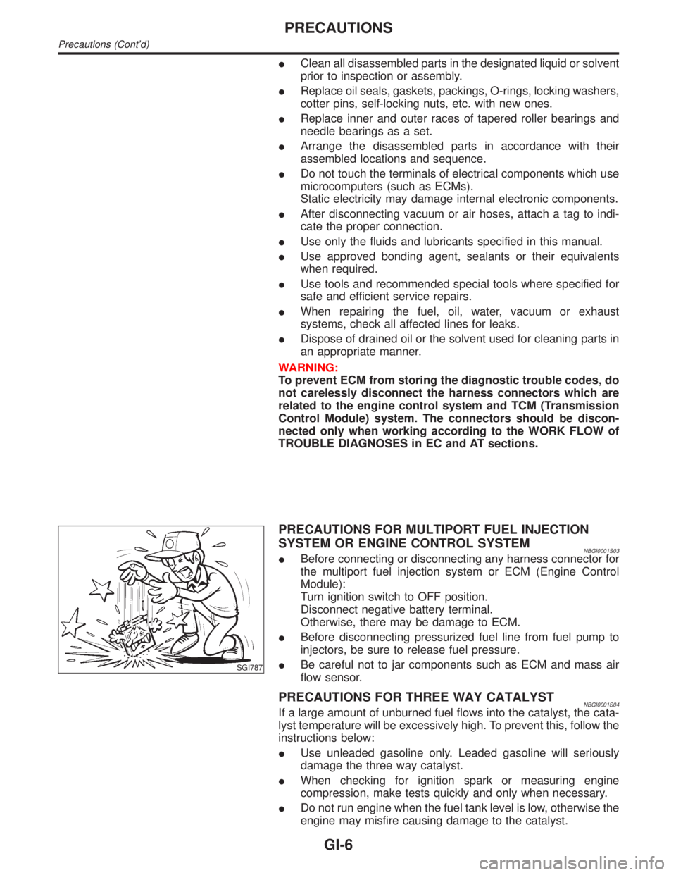
SGI787
PRECAUTIONS FOR MULTIPORT FUEL INJECTION
SYSTEM OR ENGINE CONTROL SYSTEM
NBGI0001S03IBefore connecting or disconnecting any harness connector for
the multiport fuel injection system or ECM (Engine Control
Module):
Turn ignition switch to OFF position.
Disconnect negative battery terminal.
Otherwise, there may be damage to ECM.
IBefore disconnecting pressurized fuel line from fuel pump to
injectors, be sure to release fuel pressure.
IBe careful not to jar components such as ECM and mass air
flow sensor.
PRECAUTIONS FOR THREE WAY CATALYSTNBGI0001S04If a large amount of unburned fuel flows into the catalyst, the cata-
lyst temperature will be excessively high. To prevent this, follow the
instructions below:
IUse unleaded gasoline only. Leaded gasoline will seriously
damage the three way catalyst.
IWhen checking for ignition spark or measuring engine
compression, make tests quickly and only when necessary.
IDo not run engine when the fuel tank level is low, otherwise the
engine may misfire causing damage to the catalyst.
PRECAUTIONS
Precautions (Cont'd)
GI-6
Page 1954 of 2395
CHECKING FOR REFRIGERANT LEAKS=NBHA0078IPerform a visual inspection of all refrigeration parts, fittings,
hoses and components for signs of A/C lubricant leakage,
damage and corrosion. A/C lubricant leakage may indicate an
area of refrigerant leakage. Allow extra inspection time in these
areas when using either an electronic refrigerant leak detector
or fluorescent dye leak detector.
IIf dye is observed, confirm the leak with an electronic refriger-
ant leak detector. It is possible a prior leak was repaired and
not properly cleaned.
IWhen searching for leaks, do not stop when one leak is found
but continue to check for additional leaks at all system compo-
nents and connections.
IWhen searching for refrigerant leaks using an electronic leak
detector, move the probe along the suspected leak area at 1
to 2 inches per second and no further than 1/4 inch from the
component.
NOTE:
Moving the electronic leak detector probe slower and closer to
the suspected leak area will improve the chances of finding a
leak.
CHECKING SYSTEM FOR LEAKS USING THE
FLUORESCENT LEAK DETECTOR
NBHA01161. Check A/C system for leaks using the UV lamp and safety
glasses (J-42220) in a low sunlight area (area without windows
preferable). Illuminate all components, fittings and lines. The
dye will appear as a bright green/yellow area at the point of
leakage. Fluorescent dye observed at the evaporator drain
opening indicates an evaporator core assembly (tubes, core or
TXV) leak.
2. If the suspected area is difficult to see, use an adjustable mir-
ror or wipe the area with a clean shop rag or cloth, then check
the cloth with the UV lamp for dye residue.
3. After the leak is repaired, remove any residual dye using dye
cleaner (J-43872) to prevent future misdiagnosis.
4. Perform a system performance check and verify the leak repair
with an approved electronic refrigerant leak detector.
NOTE:
IOther gases in the work area or substances on the A/C
components, for example, anti-freeze, windshield washer
fluid, solvents and lubricants, may falsely trigger the leak
detector. Make sure the surfaces to be checked are clean.
Clean with a dry cloth or blow off with shop air.
IDo not allow the sensor tip of the detector to contact with
any substance. This can also cause false readings and
may damage the detector.
DYE INJECTIONNBHA0117(This procedure is only necessary when re-charging the system or
when the compressor has seized and was replaced.)
1. Check A/C system static (at rest) Pressure. Pressure must be
at least 345 kPa (50 psi).
2. Pour one bottle (1/4 ounce /7.4 cc) of the A/C refrigerant dye
into the injector tool (J-41459).
3. Connect the injector tool to the A/C LOW PRESSURE side
service fitting.
4. Start engine and switch A/C ON.
GI
MA
EM
LC
EC
FE
AT
TF
PD
AX
SU
BR
ST
RS
BT
SC
EL
IDX
SERVICE PROCEDURE
Refrigerant Lines (Cont'd)
HA-155