2001 INFINITI QX4 light
[x] Cancel search: lightPage 1658 of 2395
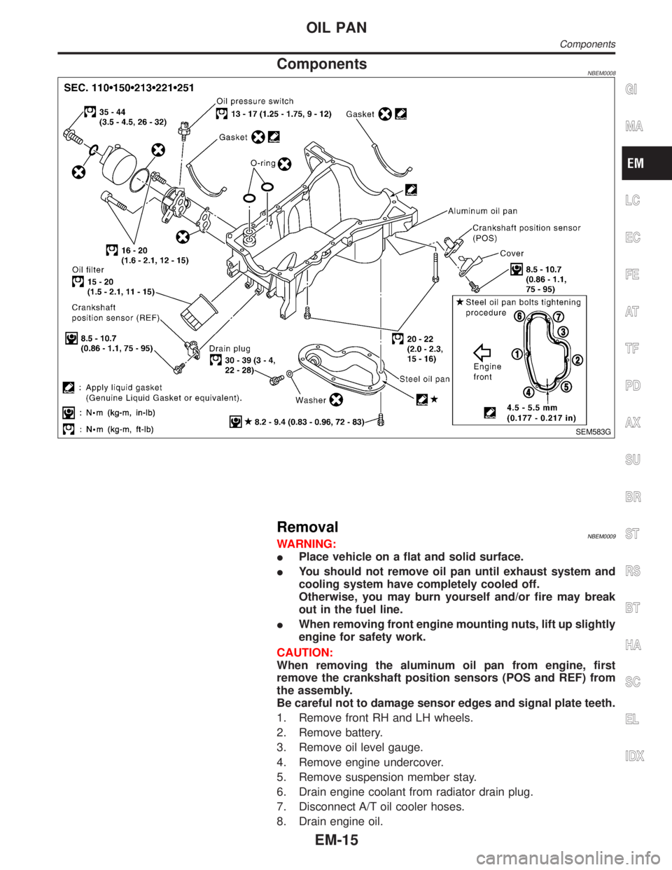
ComponentsNBEM0008
SEM583G
RemovalNBEM0009WARNING:
IPlace vehicle on a flat and solid surface.
IYou should not remove oil pan until exhaust system and
cooling system have completely cooled off.
Otherwise, you may burn yourself and/or fire may break
out in the fuel line.
IWhen removing front engine mounting nuts, lift up slightly
engine for safety work.
CAUTION:
When removing the aluminum oil pan from engine, first
remove the crankshaft position sensors (POS and REF) from
the assembly.
Be careful not to damage sensor edges and signal plate teeth.
1. Remove front RH and LH wheels.
2. Remove battery.
3. Remove oil level gauge.
4. Remove engine undercover.
5. Remove suspension member stay.
6. Drain engine coolant from radiator drain plug.
7. Disconnect A/T oil cooler hoses.
8. Drain engine oil.
GI
MA
LC
EC
FE
AT
TF
PD
AX
SU
BR
ST
RS
BT
HA
SC
EL
IDX
OIL PAN
Components
EM-15
Page 1749 of 2395

The security indicator is located on the instrument panel. The indi-
cator blinks when the ignition switch is in OFF or ACC position.
Therefore, IVIS (NATS) warns outsiders that the vehicle is
equipped with the anti-theft system.
IWhen IVIS (NATS) detects trouble, the security indicator lamp
lights up while ignition switch is in ON position.
This lighting up indicates that the anti-theft is not functioning,
so prompt service is required.
IWhen servicing IVIS (NATS) (trouble diagnoses, system initial-
ization and additional registration of other IVIS (NATS) ignition
key IDs), CONSULT-II hardware and CONSULT-II IVIS (NATS)
software is necessary.
Regarding the procedures of IVIS (NATS) initialization and
IVIS (NATS) ignition key ID registration, refer to CONSULT-II
operation manual, IVIS/NVIS.
Therefore, CONSULT-II IVIS (NATS) software (program card
and operation manual) must be kept strictly confidential to
maintain the integrity of the anti-theft function.
IWhen servicing IVIS (NATS) (trouble diagnoses, system initial-
ization and additional registration of other IVIS (NATS) ignition
key IDs), it may be necessary to re-register original key iden-
tification. Therefore, be sure to receive all keys from vehicle
owner.
A maximum of five key IDs can be registered into IVIS (NATS).
IWhen failing to start the engine first time using the key of IVIS
(NATS) (for example, when interference is caused by another
IVIS (NATS) key, an automated full road device or automated
payment device on the key ring), restart as follows.
a) Leave the ignition switch in ON position for approximately 5
seconds.
b) Turn ignition switch to OFF or LOCK position and wait approxi-
mately 5 seconds.
c) Repeat step 1 and 2.
d) Restart the engine while holding the device (which may have
caused the interference) separate from the registered NATS
key. If the no start condition re-occurs, NISSAN recommends
placing the registered IVIS (NATS) key on a separate key ring
to avoid interference from other devices.
PRECAUTIONS FOR INFINITI COMMUNICATOR (IVCS)NBGI0001S09The purpose of INFINITI Communicator is to increase security for
the vehicle owner by providing a convenient way to contact the
most appropriate emergency assistance provider during an emer-
gency.
Improper operation of the system may result in a police response.
The theft warning system also activates INFINITI Communicator.
For details, refer to INFINITI Communicator (IVCS) in the EL sec-
tion.
PRECAUTIONS
Precautions (Cont'd)
GI-4
Page 1758 of 2395
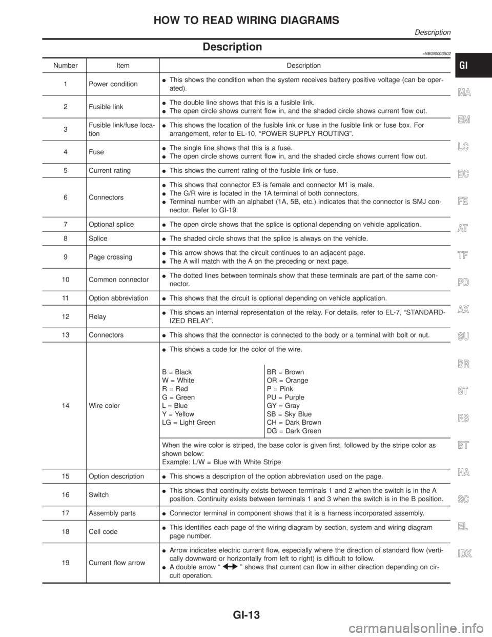
Description=NBGI0003S02
Number Item Description
1 Power conditionIThis shows the condition when the system receives battery positive voltage (can be oper-
ated).
2 Fusible linkIThe double line shows that this is a fusible link.
IThe open circle shows current flow in, and the shaded circle shows current flow out.
3Fusible link/fuse loca-
tionIThis shows the location of the fusible link or fuse in the fusible link or fuse box. For
arrangement, refer to EL-10, ªPOWER SUPPLY ROUTINGº.
4 FuseIThe single line shows that this is a fuse.
IThe open circle shows current flow in, and the shaded circle shows current flow out.
5 Current ratingIThis shows the current rating of the fusible link or fuse.
6 ConnectorsIThis shows that connector E3 is female and connector M1 is male.
IThe G/R wire is located in the 1A terminal of both connectors.
ITerminal number with an alphabet (1A, 5B, etc.) indicates that the connector is SMJ con-
nector. Refer to GI-19.
7 Optional spliceIThe open circle shows that the splice is optional depending on vehicle application.
8 SpliceIThe shaded circle shows that the splice is always on the vehicle.
9 Page crossingIThis arrow shows that the circuit continues to an adjacent page.
IThe A will match with the A on the preceding or next page.
10 Common connectorIThe dotted lines between terminals show that these terminals are part of the same con-
nector.
11 Option abbreviationIThis shows that the circuit is optional depending on vehicle application.
12 RelayIThis shows an internal representation of the relay. For details, refer to EL-7, ªSTANDARD-
IZED RELAYº.
13 ConnectorsIThis shows that the connector is connected to the body or a terminal with bolt or nut.
14 Wire colorIThis shows a code for the color of the wire.
B = Black
W = White
R = Red
G = Green
L = Blue
Y = Yellow
LG = Light GreenBR = Brown
OR = Orange
P = Pink
PU = Purple
GY = Gray
SB = Sky Blue
CH = Dark Brown
DG = Dark Green
When the wire color is striped, the base color is given first, followed by the stripe color as
shown below:
Example: L/W = Blue with White Stripe
15 Option descriptionIThis shows a description of the option abbreviation used on the page.
16 SwitchIThis shows that continuity exists between terminals 1 and 2 when the switch is in the A
position. Continuity exists between terminals 1 and 3 when the switch is in the B position.
17 Assembly partsIConnector terminal in component shows that it is a harness incorporated assembly.
18 Cell codeIThis identifies each page of the wiring diagram by section, system and wiring diagram
page number.
19 Current flow arrowIArrow indicates electric current flow, especially where the direction of standard flow (verti-
cally downward or horizontally from left to right) is difficult to follow.
IA double arrow ª
º shows that current can flow in either direction depending on cir-
cuit operation.
MA
EM
LC
EC
FE
AT
TF
PD
AX
SU
BR
ST
RS
BT
HA
SC
EL
IDX
HOW TO READ WIRING DIAGRAMS
Description
GI-13
Page 1770 of 2395
Incident Simulation TestsNBGI0004S02INTRODUCTIONNBGI0004S0201Sometimes the symptom is not present when the vehicle is brought
in for service. If possible, re-create the conditions present at the
time of the incident. Doing so may help avoid a No Trouble Found
Diagnosis. The following section illustrates ways to simulate the
conditions/environment under which the owner experiences an
electrical incident.
The section is broken into the six following topics:
IVehicle vibration
IHeat sensitive
IFreezing
IWater intrusion
IElectrical load
ICold or hot start up
Get a thorough description of the incident from the customer. It is
important for simulating the conditions of the problem.
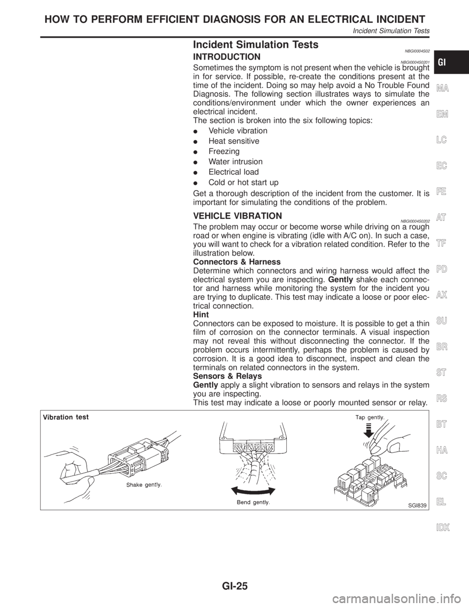
VEHICLE VIBRATIONNBGI0004S0202The problem may occur or become worse while driving on a rough
road or when engine is vibrating (idle with A/C on). In such a case,
you will want to check for a vibration related condition. Refer to the
illustration below.
Connectors & Harness
Determine which connectors and wiring harness would affect the
electrical system you are inspecting.Gentlyshake each connec-
tor and harness while monitoring the system for the incident you
are trying to duplicate. This test may indicate a loose or poor elec-
trical connection.
Hint
Connectors can be exposed to moisture. It is possible to get a thin
film of corrosion on the connector terminals. A visual inspection
may not reveal this without disconnecting the connector. If the
problem occurs intermittently, perhaps the problem is caused by
corrosion. It is a good idea to disconnect, inspect and clean the
terminals on related connectors in the system.
Sensors & Relays
Gentlyapply a slight vibration to sensors and relays in the system
you are inspecting.
This test may indicate a loose or poorly mounted sensor or relay.
SGI839
MA
EM
LC
EC
FE
AT
TF
PD
AX
SU
BR
ST
RS
BT
HA
SC
EL
IDX
HOW TO PERFORM EFFICIENT DIAGNOSIS FOR AN ELECTRICAL INCIDENT
Incident Simulation Tests
GI-25
Page 1776 of 2395
ohmmeter, contact by a single strand of wire will give reading of 0
ohms. This would indicate a good circuit. When the circuit operates,
this single strand of wire is not able to carry the current. The single
strand will have a high resistance to the current. This will be picked
up as a slight voltage drop.
Unwanted resistance can be caused by many situations as follows:
IUndersized wiring (single strand example)
ICorrosion on switch contacts
ILoose wire connections or splices.
If repairs are needed always use wire that is of the same or larger
gauge.
Measuring Voltage Drop Ð Accumulated Method
1) Connect the voltmeter across the connector or part of the cir-
cuit you want to check. The positive lead of the voltmeter
should be closer to power and the negative lead closer to
ground.
2) Operate the circuit.
3) The voltmeter will indicate how many volts are being used to
ªpushº current through that part of the circuit.
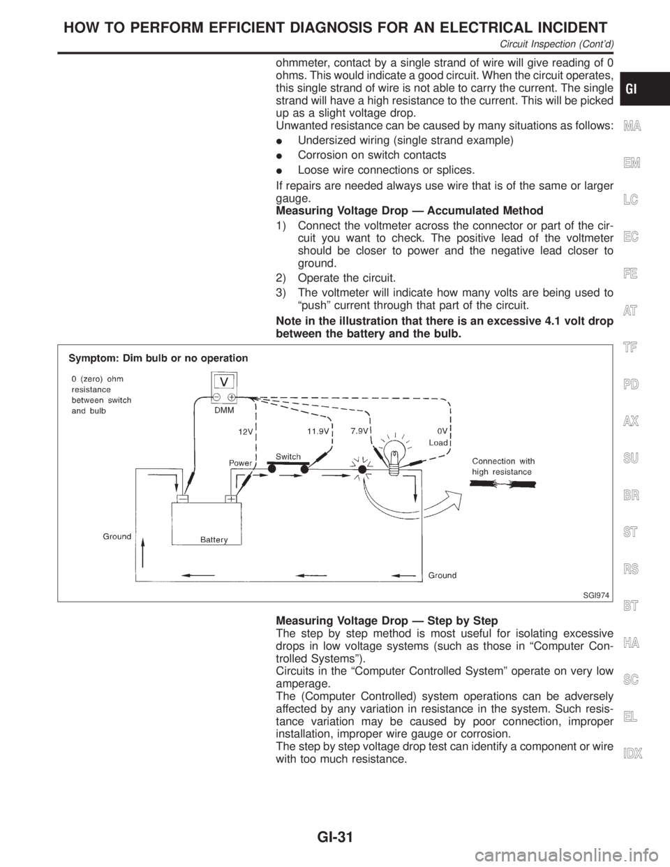
Note in the illustration that there is an excessive 4.1 volt drop
between the battery and the bulb.
SGI974
Measuring Voltage Drop Ð Step by Step
The step by step method is most useful for isolating excessive
drops in low voltage systems (such as those in ªComputer Con-
trolled Systemsº).
Circuits in the ªComputer Controlled Systemº operate on very low
amperage.
The (Computer Controlled) system operations can be adversely
affected by any variation in resistance in the system. Such resis-
tance variation may be caused by poor connection, improper
installation, improper wire gauge or corrosion.
The step by step voltage drop test can identify a component or wire
with too much resistance.
MA
EM
LC
EC
FE
AT
TF
PD
AX
SU
BR
ST
RS
BT
HA
SC
EL
IDX
HOW TO PERFORM EFFICIENT DIAGNOSIS FOR AN ELECTRICAL INCIDENT
Circuit Inspection (Cont'd)
GI-31
Page 1777 of 2395
![INFINITI QX4 2001 Factory Service Manual SGI854
CONTROL UNIT CIRCUIT TESTNBGI0004S0307System Description: When the switch is ON, the control unit lights
up the lamp.
MGI034A
Input-output voltage chart
Pin No. Item ConditionVoltage
value [V]I INFINITI QX4 2001 Factory Service Manual SGI854
CONTROL UNIT CIRCUIT TESTNBGI0004S0307System Description: When the switch is ON, the control unit lights
up the lamp.
MGI034A
Input-output voltage chart
Pin No. Item ConditionVoltage
value [V]I](/manual-img/42/57027/w960_57027-1776.png)
SGI854
CONTROL UNIT CIRCUIT TESTNBGI0004S0307System Description: When the switch is ON, the control unit lights
up the lamp.
MGI034A
Input-output voltage chart
Pin No. Item ConditionVoltage
value [V]In case of high resistance such as single strand [V]
*
1 Switch Switch ON Battery voltage Lower than battery voltage Approx. 8 (Example)
Switch OFF Approx. 0 Approx. 0
2 Lamp Switch ON Battery voltage Approx. 0 (Inoperative lamp)
Switch OFF Approx. 0 Approx. 0
The voltage value is based on the body ground.
* : If high resistance exists in the switch side circuit (caused by a single strand), terminal 1 does not detect battery voltage. Control unit
does not detect the switch is ON even if the switch does not turn ON. Therefore, the control unit does not supply power to light up the
lamp.
HOW TO PERFORM EFFICIENT DIAGNOSIS FOR AN ELECTRICAL INCIDENT
Circuit Inspection (Cont'd)
GI-32
Page 1778 of 2395
![INFINITI QX4 2001 Factory Service Manual MGI035A
Input-output voltage chart
Pin No. Item ConditionVoltage
value [V]In case of high resistance such as single strand [V]
*
1 Lamp Switch ON Approx. 0 Battery voltage (Inoperative lamp)
Switch OF INFINITI QX4 2001 Factory Service Manual MGI035A
Input-output voltage chart
Pin No. Item ConditionVoltage
value [V]In case of high resistance such as single strand [V]
*
1 Lamp Switch ON Approx. 0 Battery voltage (Inoperative lamp)
Switch OF](/manual-img/42/57027/w960_57027-1777.png)
MGI035A
Input-output voltage chart
Pin No. Item ConditionVoltage
value [V]In case of high resistance such as single strand [V]
*
1 Lamp Switch ON Approx. 0 Battery voltage (Inoperative lamp)
Switch OFF Battery voltage Battery voltage
2 Switch Switch ON Approx. 0 Higher than 0 Approx. 4 (Example)
Switch OFF Approx. 5 Approx. 5
The voltage value is based on the body ground.
* : If high resistance exists in the switch side circuit (caused by a single strand), terminal 2 does not detect approx. 0V. Control unit
does not detect the switch is ON even if the switch does not turn ON. Therefore, the control unit does not control ground to light up the
lamp.
MA
EM
LC
EC
FE
AT
TF
PD
AX
SU
BR
ST
RS
BT
HA
SC
EL
IDX
HOW TO PERFORM EFFICIENT DIAGNOSIS FOR AN ELECTRICAL INCIDENT
Circuit Inspection (Cont'd)
GI-33
Page 1797 of 2395
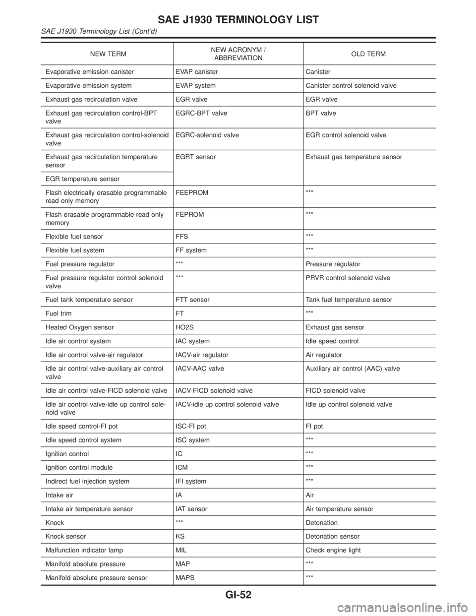
NEW TERMNEW ACRONYM /
ABBREVIATIONOLD TERM
Evaporative emission canister EVAP canister Canister
Evaporative emission system EVAP system Canister control solenoid valve
Exhaust gas recirculation valve EGR valve EGR valve
Exhaust gas recirculation control-BPT
valveEGRC-BPT valve BPT valve
Exhaust gas recirculation control-solenoid
valveEGRC-solenoid valve EGR control solenoid valve
Exhaust gas recirculation temperature
sensorEGRT sensor Exhaust gas temperature sensor
EGR temperature sensor
Flash electrically erasable programmable
read only memoryFEEPROM ***
Flash erasable programmable read only
memoryFEPROM ***
Flexible fuel sensor FFS ***
Flexible fuel system FF system ***
Fuel pressure regulator *** Pressure regulator
Fuel pressure regulator control solenoid
valve*** PRVR control solenoid valve
Fuel tank temperature sensor FTT sensor Tank fuel temperature sensor
Fuel trim FT ***
Heated Oxygen sensor HO2S Exhaust gas sensor
Idle air control system IAC system Idle speed control
Idle air control valve-air regulator IACV-air regulator Air regulator
Idle air control valve-auxiliary air control
valveIACV-AAC valve Auxiliary air control (AAC) valve
Idle air control valve-FICD solenoid valve IACV-FICD solenoid valve FICD solenoid valve
Idle air control valve-idle up control sole-
noid valveIACV-idle up control solenoid valve Idle up control solenoid valve
Idle speed control-FI pot ISC-FI pot FI pot
Idle speed control system ISC system ***
Ignition control IC ***
Ignition control module ICM ***
Indirect fuel injection system IFI system ***
Intake air IA Air
Intake air temperature sensor IAT sensor Air temperature sensor
Knock *** Detonation
Knock sensor KS Detonation sensor
Malfunction indicator lamp MIL Check engine light
Manifold absolute pressure MAP ***
Manifold absolute pressure sensor MAPS ***
SAE J1930 TERMINOLOGY LIST
SAE J1930 Terminology List (Cont'd)
GI-52