2001 INFINITI QX4 light
[x] Cancel search: lightPage 1962 of 2395
Brake fluid change ...........................................BR-7
Brake fluid level .............................................MA-25
Brake fluid level and line check .......................BR-7
Brake hydraulic line ..........................................BR-9
Brake inspection ............................................MA-25
Brake lines and cables inspection .................MA-25
Brake lining wear temporary checking ..........MA-26
Brake master cylinder ....................................BR-16
Brake pedal ....................................................BR-14
Bulb specifications ........................................EL-456
Bumper, front ..................................................BT-12
Bumper, rear ...................................................BT-15
BYPS/V - Wiring diagram ....................EC-587, 594
C
Camshaft inspection ......................................EM-42
Camshaft position sensor (PHASE) .............EC-342
Canister-See EVAP canister ..........................EC-32
Center bearing assembly (propeller
shaft) .............................................................PD-9
Center bearing disassembly (propeller
shaft) .............................................................PD-7
Center case (Transfer) ..................................TF-123
CHARGE - Wiring diagram ............................SC-20
Charging system ............................................SC-19
Chassis and body maintenance ....................MA-21
CHIME - Wiring diagram...............................EL-127
CIGAR - Wiring diagram ...............................EL-148
Cigarette lighter.............................................EL-148
Circuit breaker.................................................EL-16
CKPS - Wiring diagram ................................EC-334
Closed loop control (Left bank) ....................EC-491
Closed loop control (Right bank) .................EC-491
Closed throttle position switch .....................EC-431
Clutch drum (Transfer) ..................................TF-125
Clutch force release limit adjustment .............TF-39
Clutch pressure switch (Transfer) .................TF-111
Coil spring (front)..............................................SU-8
Coil spring (rear) ............................................SU-18
Collision diagnosis..........................................RS-59
Combination lamp, front, removal and
installation ...................................................BT-12
Combination lamp, rear, removal and
installation ...................................................BT-35
Combination meter..........................................EL-94
Combination meter removal and instal-
lation - See Instrument panel ......................BT-21
Combination switch .........................................EL-28
COMPAS - Wiring diagram ...........................EL-111
Compass .......................................................EL-110
Component Location (auto A/C).....................HA-27
Compression pressure ...................................EM-14
Compressor clutch removal and
installation .................................................HA-150
Compressor precaution ....................................HA-6
Compressor special service tool ....................HA-10
Connecting rod...............................................EM-65
Connecting rod bearing clearance.................EM-69
Connecting rod bushing clearance ................EM-70Connector inspection .......................................GI-21
Console box - See Instrument panel ..............BT-21
CONSULT for ABS .........................................BR-43
CONSULT for all-mode 4WD ..........................TF-30
CONSULT for engine .....................................EC-81
CONSULT-II general information .....................GI-38
Control valve (A/T) ........................................AT-301
Control valve (Transfer) ................................TF-128
Converter housing installation .......................AT-278
Coolant mixture ratio......................................MA-12
Coolant replacement ......................................MA-14
Cooling circuit (engine) ...................................LC-10
``Crankcase emission control system -
See positive crankcase ventilation''............EC-38
Crankshaft ......................................................EM-67
Crankshaft position sensor (POS) ...............EC-334
Crankshaft position sensor (POS)
chipping ....................................................EC-517
Crankshaft position sensor (REF) ................EC-510
Cruise control - See ASCD ...........................EL-221
Cylinder block ................................................EM-61
Cylinder head .................................................EM-38
Cylinder head bolt tightening .........................EM-49
D
Data link connector for Consult......................EC-81
Daytime light system.......................................EL-46
Daytime running light - See Daytime
light system .................................................EL-46
DEF - Wiring diagram ...................................EL-153
Detonation sensor - See Knock sensor .......EC-328
Diagnostic trouble code (DTC) for OBD
system ....................................................EC-8, 60
Diagnostic trouble code (DTC) inspec-
tion priority chart .......................................EC-116
Differential carrier assembly.....................PD-30, 57
Differential carrier disassembly ......................PD-44
Differential gear oil replacement ....................MA-24
Dimensions ......................................................GI-43
D/LOCK - Wiring diagram .............................EL-256
Dome light - See Interior lamp .......................EL-88
Door glass .......................................................BT-18
Door lock .........................................................BT-18
Door mirror ......................................................BT-56
Door trim .........................................................BT-30
Door, front .......................................................BT-18
Door, rear ........................................................BT-20
Drive belt inspection ......................................MA-13
Drive chain (Transfer) ...................................TF-125
Drive pinion diff. inspection ......................PD-23, 47
Drive pinion height ...................................PD-25, 53
Drive plate runout ..........................................EM-70
Drive shaft (front)............................................AX-10
Dropping resistor (A/T) ..................................AT-167
DTC work support ..........................................EC-93
DTRL - Wiring diagram ...................................EL-51
GI
MA
EM
LC
EC
FE
AT
TF
PD
AX
SU
BR
ST
RS
BT
HA
SC
EL
ALPHABETICAL INDEX
IDX-3
Page 2014 of 2395
SMA010
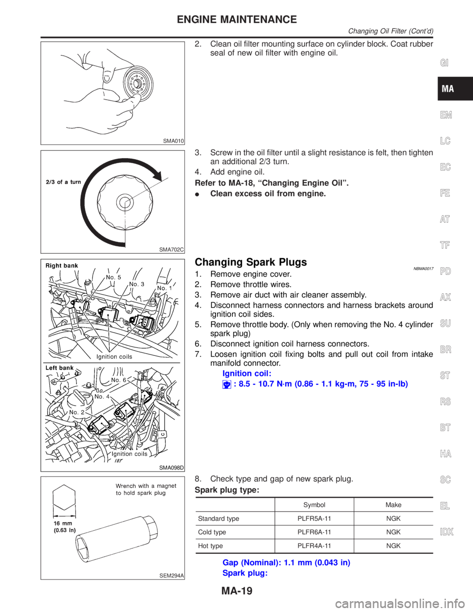
2. Clean oil filter mounting surface on cylinder block. Coat rubber
seal of new oil filter with engine oil.
SMA702C
3. Screw in the oil filter until a slight resistance is felt, then tighten
an additional 2/3 turn.
4. Add engine oil.
Refer to MA-18, ªChanging Engine Oilº.
IClean excess oil from engine.
SMA098D
Changing Spark PlugsNBMA00171. Remove engine cover.
2. Remove throttle wires.
3. Remove air duct with air cleaner assembly.
4. Disconnect harness connectors and harness brackets around
ignition coil sides.
5. Remove throttle body. (Only when removing the No. 4 cylinder
spark plug)
6. Disconnect ignition coil harness connectors.
7. Loosen ignition coil fixing bolts and pull out coil from intake
manifold connector.
Ignition coil:
: 8.5 - 10.7 N´m (0.86 - 1.1 kg-m, 75 - 95 in-lb)
SEM294A
8. Check type and gap of new spark plug.
Spark plug type:
Symbol Make
Standard type PLFR5A-11 NGK
Cold type PLFR6A-11 NGK
Hot type PLFR4A-11 NGK
Gap (Nominal): 1.1 mm (0.043 in)
Spark plug:
GI
EM
LC
EC
FE
AT
TF
PD
AX
SU
BR
ST
RS
BT
HA
SC
EL
IDX
ENGINE MAINTENANCE
Changing Oil Filter (Cont'd)
MA-19
Page 2033 of 2395
SPD475A
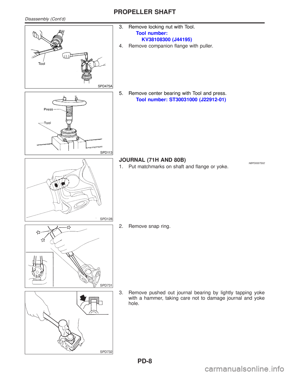
3. Remove locking nut with Tool.
Tool number:
KV38108300 (J44195)
4. Remove companion flange with puller.
SPD113
5. Remove center bearing with Tool and press.
Tool number: ST30031000 (J22912-01)
SPD128
JOURNAL (71H AND 80B)NBPD0007S021. Put matchmarks on shaft and flange or yoke.
SPD731
2. Remove snap ring.
SPD732
3. Remove pushed out journal bearing by lightly tapping yoke
with a hammer, taking care not to damage journal and yoke
hole.
PROPELLER SHAFT
Disassembly (Cont'd)
PD-8
Page 2036 of 2395
Service Data and Specifications (SDS)
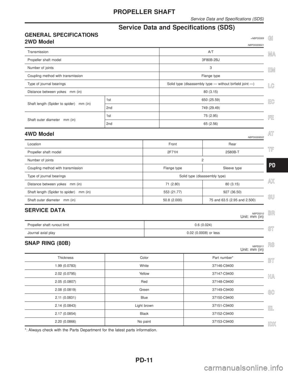
GENERAL SPECIFICATIONS=NBPD00092WD ModelNBPD0009S01
TransmissionA/T
Propeller shaft model3F80B-2BJ
Number of joints3
Coupling method with transmissionFlange type
Type of journal bearings Solid type (disassembly type Ð without birfield joint Ð)
Distance between yokes mm (in)80 (3.15)
Shaft length (Spider to spider) mm (in)1st 650 (25.59)
2nd 749 (29.49)
Shaft outer diameter mm (in)1st 75 (2.95)
2nd 65 (2.56)
4WD ModelNBPD0009S02
LocationFront Rear
Propeller shaft model 2F71H 2S80B-T
Number of joints2
Coupling method with transmission Flange type Sleeve type
Type of journal bearingsSolid type (disassembly type)
Distance between yokes mm (in) 71 (2.80) 80 (3.15)
Shaft length (Spider to spider) mm (in) 553 (21.77) 927 (36.50)
Shaft outer diameter mm (in) 50.8 (2.000) 75 and 63.5 (2.95 and 2.500)
SERVICE DATANBPD0010Unit: mm (in)
Propeller shaft runout limit0.6 (0.024)
Journal axial play0.02 (0.0008) or less
SNAP RING (80B)NBPD0011Unit: mm (in)
Thickness Color Part number*
1.99 (0.0783) White 37146-C9400
2.02 (0.0795) Yellow 37147-C9400
2.05 (0.0807) Red 37148-C9400
2.08 (0.0819) Green 37149-C9400
2.11 (0.0831) Blue 37150-C9400
2.14 (0.0843) Light brown 37151-C9400
2.17 (0.0854) Black 37152-C9400
2.20 (0.0866) No paint 37153-C9400
*: Always check with the Parts Department for the latest parts information.
GI
MA
EM
LC
EC
FE
AT
TF
AX
SU
BR
ST
RS
BT
HA
SC
EL
IDX
PROPELLER SHAFT
Service Data and Specifications (SDS)
PD-11
Page 2037 of 2395
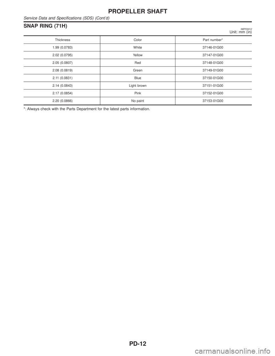
SNAP RING (71H)NBPD0012Unit: mm (in)
Thickness Color Part number*
1.99 (0.0783) White 37146-01G00
2.02 (0.0795) Yellow 37147-01G00
2.05 (0.0807) Red 37148-01G00
2.08 (0.0819) Green 37149-01G00
2.11 (0.0831) Blue 37150-01G00
2.14 (0.0843) Light brown 37151-01G00
2.17 (0.0854) Pink 37152-01G00
2.20 (0.0866) No paint 37153-01G00
*: Always check with the Parts Department for the latest parts information.
PROPELLER SHAFT
Service Data and Specifications (SDS) (Cont'd)
PD-12
Page 2049 of 2395
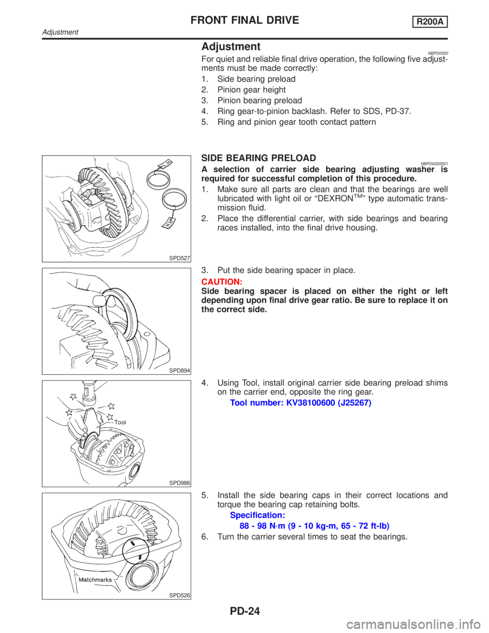
AdjustmentNBPD0020For quiet and reliable final drive operation, the following five adjust-
ments must be made correctly:
1. Side bearing preload
2. Pinion gear height
3. Pinion bearing preload
4. Ring gear-to-pinion backlash. Refer to SDS, PD-37.
5. Ring and pinion gear tooth contact pattern
SPD527
SIDE BEARING PRELOADNBPD0020S01A selection of carrier side bearing adjusting washer is
required for successful completion of this procedure.
1. Make sure all parts are clean and that the bearings are well
lubricated with light oil or ªDEXRON
TMº type automatic trans-
mission fluid.
2. Place the differential carrier, with side bearings and bearing
races installed, into the final drive housing.
SPD894
3. Put the side bearing spacer in place.
CAUTION:
Side bearing spacer is placed on either the right or left
depending upon final drive gear ratio. Be sure to replace it on
the correct side.
SPD986
4. Using Tool, install original carrier side bearing preload shims
on the carrier end, opposite the ring gear.
Tool number: KV38100600 (J25267)
SPD526
5. Install the side bearing caps in their correct locations and
torque the bearing cap retaining bolts.
Specification:
88 - 98 N´m (9 - 10 kg-m, 65 - 72 ft-lb)
6. Turn the carrier several times to seat the bearings.
FRONT FINAL DRIVER200A
Adjustment
PD-24
Page 2057 of 2395
![INFINITI QX4 2001 Factory Service Manual SPD554
6. Install differential case assembly on ring gear.
7. Apply locking agent [Locktite (stud lock) or equivalent] to ring
gear bolts, and install them.
Tighten bolts in a criss-cross pattern, lig INFINITI QX4 2001 Factory Service Manual SPD554
6. Install differential case assembly on ring gear.
7. Apply locking agent [Locktite (stud lock) or equivalent] to ring
gear bolts, and install them.
Tighten bolts in a criss-cross pattern, lig](/manual-img/42/57027/w960_57027-2056.png)
SPD554
6. Install differential case assembly on ring gear.
7. Apply locking agent [Locktite (stud lock) or equivalent] to ring
gear bolts, and install them.
Tighten bolts in a criss-cross pattern, lightly tapping bolt head
with a hammer.
PD353
8. Press-fit side bearing inner cones on differential case with Tool.
Tool number:
A KV38100300 (J25523)
B ST33061000 (J8107-2)
SPD679
FINAL DRIVE HOUSINGNBPD0021S031. Press-fit front and rear bearing outer races with Tools.
Tool number:
A ST30611000 (J25742-1)
B ST30621000 (J25742-5)
C ST30613000 (J25742-3)
SPD377
2. Select drive pinion height adjusting washer and pinion bearing
adjusting washer. Refer to ªPINION GEAR HEIGHT AND PIN-
ION BEARING PRELOADº, PD-25.
3. Install drive pinion height adjusting washer in drive pinion, and
press-fit pinion rear bearing inner cone in it, using press and
Tool.
Tool number:
ST30901000 (J26010-01)
FRONT FINAL DRIVER200A
Assembly (Cont'd)
PD-32
Page 2078 of 2395
SPD364A
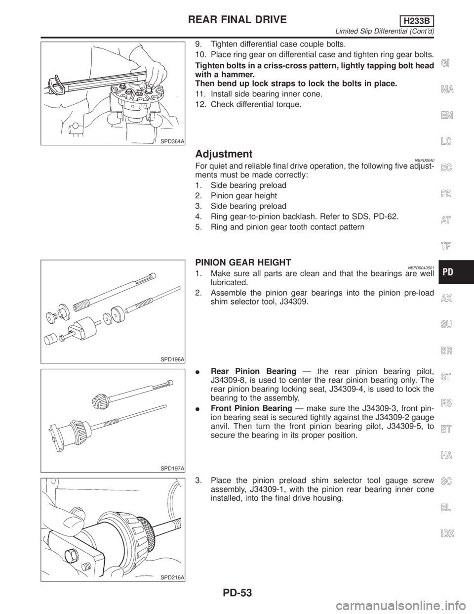
9. Tighten differential case couple bolts.
10. Place ring gear on differential case and tighten ring gear bolts.
Tighten bolts in a criss-cross pattern, lightly tapping bolt head
with a hammer.
Then bend up lock straps to lock the bolts in place.
11. Install side bearing inner cone.
12. Check differential torque.
AdjustmentNBPD0040For quiet and reliable final drive operation, the following five adjust-
ments must be made correctly:
1. Side bearing preload
2. Pinion gear height
3. Side bearing preload
4. Ring gear-to-pinion backlash. Refer to SDS, PD-62.
5. Ring and pinion gear tooth contact pattern
SPD196A
PINION GEAR HEIGHTNBPD0040S011. Make sure all parts are clean and that the bearings are well
lubricated.
2. Assemble the pinion gear bearings into the pinion pre-load
shim selector tool, J34309.
SPD197A
IRear Pinion BearingÐ the rear pinion bearing pilot,
J34309-8, is used to center the rear pinion bearing only. The
rear pinion bearing locking seat, J34309-4, is used to lock the
bearing to the assembly.
IFront Pinion BearingÐ make sure the J34309-3, front pin-
ion bearing seat is secured tightly against the J34309-2 gauge
anvil. Then turn the front pinion bearing pilot, J34309-5, to
secure the bearing in its proper position.
SPD216A
3. Place the pinion preload shim selector tool gauge screw
assembly, J34309-1, with the pinion rear bearing inner cone
installed, into the final drive housing.
GI
MA
EM
LC
EC
FE
AT
TF
AX
SU
BR
ST
RS
BT
HA
SC
EL
IDX
REAR FINAL DRIVEH233B
Limited Slip Differential (Cont'd)
PD-53