Page 2290 of 2395

SMT772D
TRANSFER CONTROL UNIT INSPECTION TABLENBTF0018S02(Data are reference values.)
Terminal
No.Item Condition Judgement standard
12-4WD shift solenoid
valve
&
4WD shift switch is set to ª2WDº
position.Less than 1V
4WD shift switch is set to any posi-
tion other than ª2WDº.Battery voltage
24WD shift indicator lamp
(2WD)
Lamp lights while system is operating
properly.Less than 1V
&
2WD indicator lamp does not come
on.Battery voltage
3 Ground Ð Ð
4Transfer shift relay
(High)While actuator is operating
(4H,4LO)Battery voltage
Actuator does not operate. Less than 1V
5 4WD warning lampLamp comes ON. (when engine is
stopped.)
(Fail-safe condition appears on
display, engine is stopped, actuator
position detection switch is
inoperative, oil temperature is too
high and/or tires of different size are
installed.)Less than 1V
Except above Battery voltage
6 Ground Ð Ð Ð
7 PNP switch (R position)
&
A/T selector lever is set to ªreverseº
position.Battery voltage
A/T selector lever is set to any posi-
tion other than ªreverseº.Less than 1V
8ÐÐÐÐ
GI
MA
EM
LC
EC
FE
AT
PD
AX
SU
BR
ST
RS
BT
HA
SC
EL
IDX
TROUBLE DIAGNOSIS Ð GENERAL DESCRIPTION
Transfer Control Unit Terminals and Reference Value (Cont'd)
TF-55
Page 2358 of 2395
SMT877C
Rear Case
DISASSEMBLYNBTF00771. Remove neutral-4LO switch and ATP switch.
2. Remove bolts.
SMT878C
3. Remove rear case from center case by tapping it lightly with a
plastic hammer.
SMT883C
Center Case
DISASSEMBLYNBTF00781. Remove oil pump shaft from main oil pump.
SMT884C
2. Remove stem bleeder from bleeder hole.
SMT844DB
3. Remove lock nut from companion flange.
IDo not reuse lock nut.
GI
MA
EM
LC
EC
FE
AT
PD
AX
SU
BR
ST
RS
BT
HA
SC
EL
IDX
DISASSEMBLY
Rear Case
TF-123
Page 2370 of 2395
SMT996C
2. Remove bolts to detach transfer cover.
IDo not reuse bolts.
SMT997C
3. Remove oil seal from transfer cover.
IDo not reuse oil seal.
SMT998C
4. Remove snap ring from main gear bearing.
IDo not reuse snap ring.
SMT999C
5. Remove sun gear by tapping it lightly.
SMT001D
6. Remove snap ring from sun gear.
IDo not reuse snap ring as it is a selective part.
7. Remove washer from sun gear.
GI
MA
EM
LC
EC
FE
AT
PD
AX
SU
BR
ST
RS
BT
HA
SC
EL
IDX
DISASSEMBLY
Front Case (Cont'd)
TF-135
Page 2384 of 2395

SMT969C
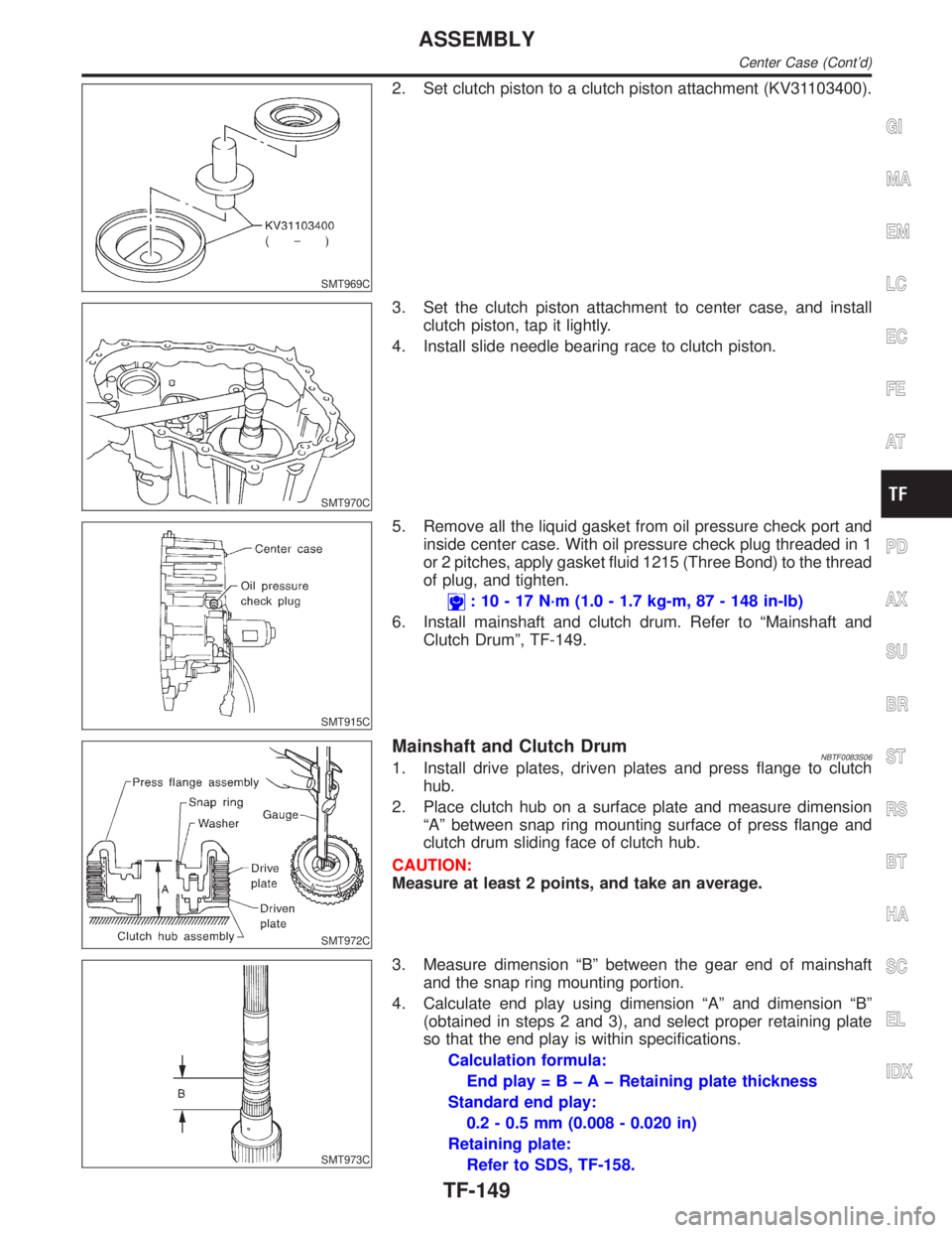
2. Set clutch piston to a clutch piston attachment (KV31103400).
SMT970C
3. Set the clutch piston attachment to center case, and install
clutch piston, tap it lightly.
4. Install slide needle bearing race to clutch piston.
SMT915C
5. Remove all the liquid gasket from oil pressure check port and
inside center case. With oil pressure check plug threaded in 1
or 2 pitches, apply gasket fluid 1215 (Three Bond) to the thread
of plug, and tighten.
: 10 - 17 N´m (1.0 - 1.7 kg-m, 87 - 148 in-lb)
6. Install mainshaft and clutch drum. Refer to ªMainshaft and
Clutch Drumº, TF-149.
SMT972C
Mainshaft and Clutch DrumNBTF0083S061. Install drive plates, driven plates and press flange to clutch
hub.
2. Place clutch hub on a surface plate and measure dimension
ªAº between snap ring mounting surface of press flange and
clutch drum sliding face of clutch hub.
CAUTION:
Measure at least 2 points, and take an average.
SMT973C
3. Measure dimension ªBº between the gear end of mainshaft
and the snap ring mounting portion.
4. Calculate end play using dimension ªAº and dimension ªBº
(obtained in steps 2 and 3), and select proper retaining plate
so that the end play is within specifications.
Calculation formula:
End play = B þ A þ Retaining plate thickness
Standard end play:
0.2 - 0.5 mm (0.008 - 0.020 in)
Retaining plate:
Refer to SDS, TF-158.
GI
MA
EM
LC
EC
FE
AT
PD
AX
SU
BR
ST
RS
BT
HA
SC
EL
IDX
ASSEMBLY
Center Case (Cont'd)
TF-149
Page 2389 of 2395
SMT894C
4. Make sure the two claws of oil gutter are securely attached to
slots in center case.
SMT895C
5. With the claws of oil gutter held by a finger, install center case
assembly to front case assembly.
CAUTION:
Pay careful attention so that mainshaft end does not damage
radial needle bearing in sun gear assembly.
6. Tap center case lightly with a rubber hammer or the like and
press-fit front drive shaft bearing into front case.
SMT896C
7. Make sure oil gutter rear end protrudes from point ªAº in the
figure.
8. Tighten bolts to specified torque.
: 41 - 48 N´m (4.2 - 4.9 kg-m, 30 - 35 ft-lb)
IBe sure to install air breather hose clamp, connector
bracket and harness clip.
SMT883C
9. Fit double-flat end of oil pump shaft into slot of main oil pump
and install it.
NOTE:
When oil pump shaft is rotated slightly, it drops into position where
both parts fit.
SMT884C
10. Install stem bleeder to center case.
ASSEMBLY
Final Assembly (Cont'd)
TF-154