Page 2190 of 2395
CAUTION:
Do not hold the steering wheel in a locked position for more
than 15 seconds.
4. If fluid leakage at connectors is noticed, loosen flare nut and
then retighten.
Do not overtighten connector as this can damage O-ring,
washer and connector.
5. Check rack boots for accumulation of power steering fluid.
Bleeding Hydraulic SystemNBST00131. Raise front end of vehicle until wheels are clear of the ground.
2. Add fluid into oil tank to specified level. Then, quickly turn
steering wheel fully to right and left and lightly touch steering
stoppers.
Repeat steering wheel operation until fluid level no longer
decreases.
3. Start engine.
Repeat step 2 above.
IIncomplete air bleeding will cause the following to occur. When
this happens, bleed air again.
a) Air bubbles in reservoir tank
b) Clicking noise in oil pump
c) Excessive buzzing in oil pump
Fluid noise may occur in the valve or oil pump. This is common
when the vehicle is stationary or while turning steering wheel
slowly. This does not affect performance or durability of the system.
SST491B
SST090B
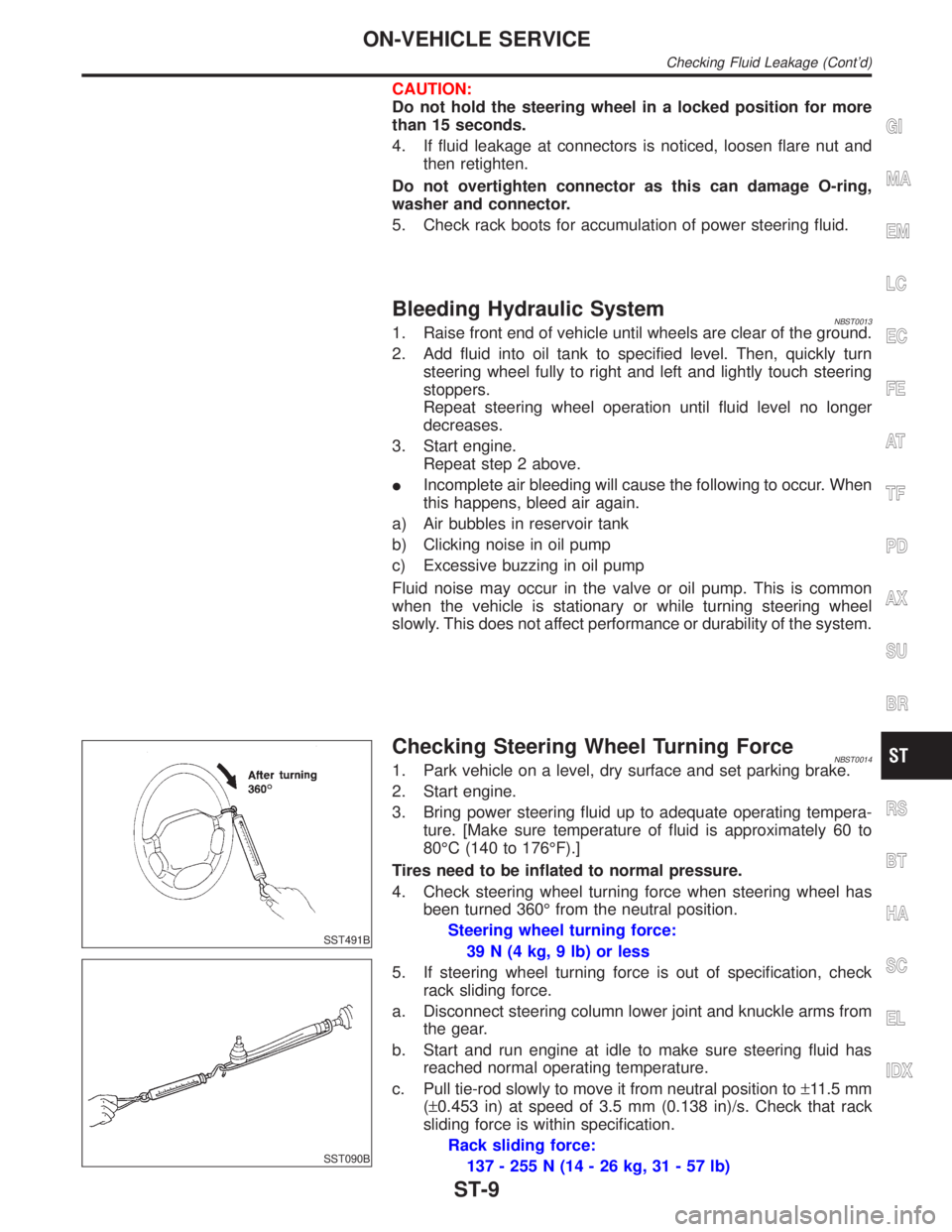
Checking Steering Wheel Turning ForceNBST00141. Park vehicle on a level, dry surface and set parking brake.
2. Start engine.
3. Bring power steering fluid up to adequate operating tempera-
ture. [Make sure temperature of fluid is approximately 60 to
80ÉC (140 to 176ÉF).]
Tires need to be inflated to normal pressure.
4. Check steering wheel turning force when steering wheel has
been turned 360É from the neutral position.
Steering wheel turning force:
39 N (4 kg, 9 lb) or less
5. If steering wheel turning force is out of specification, check
rack sliding force.
a. Disconnect steering column lower joint and knuckle arms from
the gear.
b. Start and run engine at idle to make sure steering fluid has
reached normal operating temperature.
c. Pull tie-rod slowly to move it from neutral position to±11.5 mm
(±0.453 in) at speed of 3.5 mm (0.138 in)/s. Check that rack
sliding force is within specification.
Rack sliding force:
137 - 255 N (14 - 26 kg, 31 - 57 lb)
GI
MA
EM
LC
EC
FE
AT
TF
PD
AX
SU
BR
RS
BT
HA
SC
EL
IDX
ON-VEHICLE SERVICE
Checking Fluid Leakage (Cont'd)
ST-9
Page 2195 of 2395
SST606C
SST607C
InspectionNBST0019IWhen steering wheel does not turn smoothly, check the steer-
ing column as follows and replace damaged parts.
a) Check column bearings for damage and unevenness. Lubri-
cate with recommended multi-purpose grease or replace steer-
ing column as an assembly, if necessary.
b) Check steering column lower shaft for deformation and break-
age. Replace if necessary.
IWhen the vehicle comes into a light collision, check length ªL
1º,
ªL
2º and ªL3º.
Steering column length ªL
1º:
716.7 - 718.7 mm (28.22 - 28.30 in)
Steering column lower shaft length ªL
2º:
178 - 180 mm (7.01 - 7.09 in)
Steering column upper joint length ªL
3º:
430.7 - 432.7 mm (16.96 - 17.04 in)
If out of the specifications, replace steering column upper joint
or steering column as an assembly.
SST582BE
TILT MECHANISMNBST0019S01After installing steering column, check tilt mechanism operation.
STEERING WHEEL AND STEERING COLUMN
Inspection
ST-14
Page 2205 of 2395
SST609C
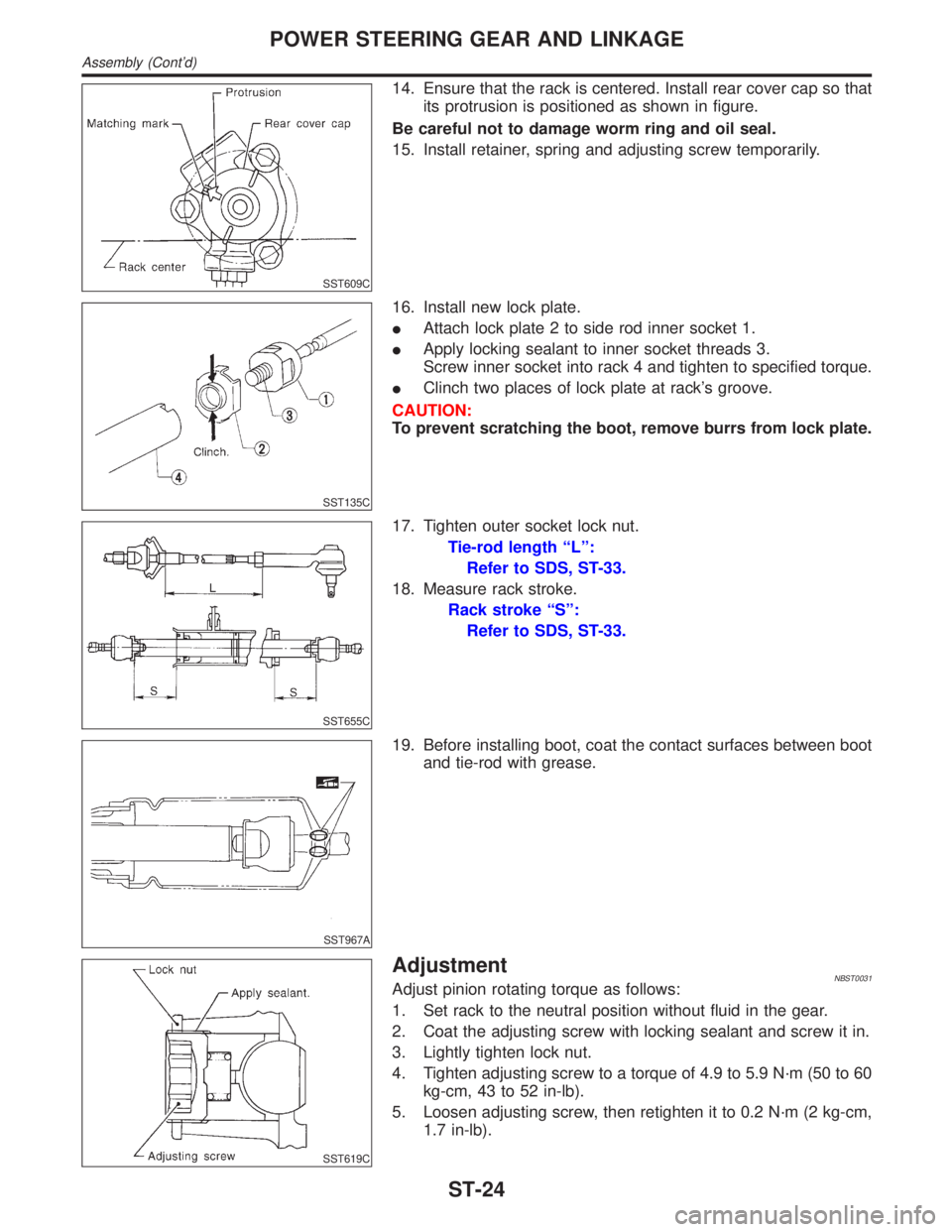
14. Ensure that the rack is centered. Install rear cover cap so that
its protrusion is positioned as shown in figure.
Be careful not to damage worm ring and oil seal.
15. Install retainer, spring and adjusting screw temporarily.
SST135C
16. Install new lock plate.
IAttach lock plate 2 to side rod inner socket 1.
IApply locking sealant to inner socket threads 3.
Screw inner socket into rack 4 and tighten to specified torque.
IClinch two places of lock plate at rack's groove.
CAUTION:
To prevent scratching the boot, remove burrs from lock plate.
SST655C
17. Tighten outer socket lock nut.
Tie-rod length ªLº:
Refer to SDS, ST-33.
18. Measure rack stroke.
Rack stroke ªSº:
Refer to SDS, ST-33.
SST967A
19. Before installing boot, coat the contact surfaces between boot
and tie-rod with grease.
SST619C
AdjustmentNBST0031Adjust pinion rotating torque as follows:
1. Set rack to the neutral position without fluid in the gear.
2. Coat the adjusting screw with locking sealant and screw it in.
3. Lightly tighten lock nut.
4. Tighten adjusting screw to a torque of 4.9 to 5.9 N´m (50 to 60
kg-cm, 43 to 52 in-lb).
5. Loosen adjusting screw, then retighten it to 0.2 N´m (2 kg-cm,
1.7 in-lb).
POWER STEERING GEAR AND LINKAGE
Assembly (Cont'd)
ST-24
Page 2210 of 2395
InspectionNBST0035IIf pulley is cracked or deformed, replace it.
IIf an oil leak is found around pulley shaft oil seal, replace the
seal.
ICheck the casing and the inside of the rear body for damage.
If damages are found in the rear body, replace the entire rear
body. If the casing is damaged, replace the entire power steer-
ing pump as an assembly.
ICheck the cam ring for damage. If damage is found, replace
the cam ring, rotor and vane as a set.
ICheck the side plates (front and rear) for damage. If damage
is found, replace the side plates as a set (front and rear).
SST934C
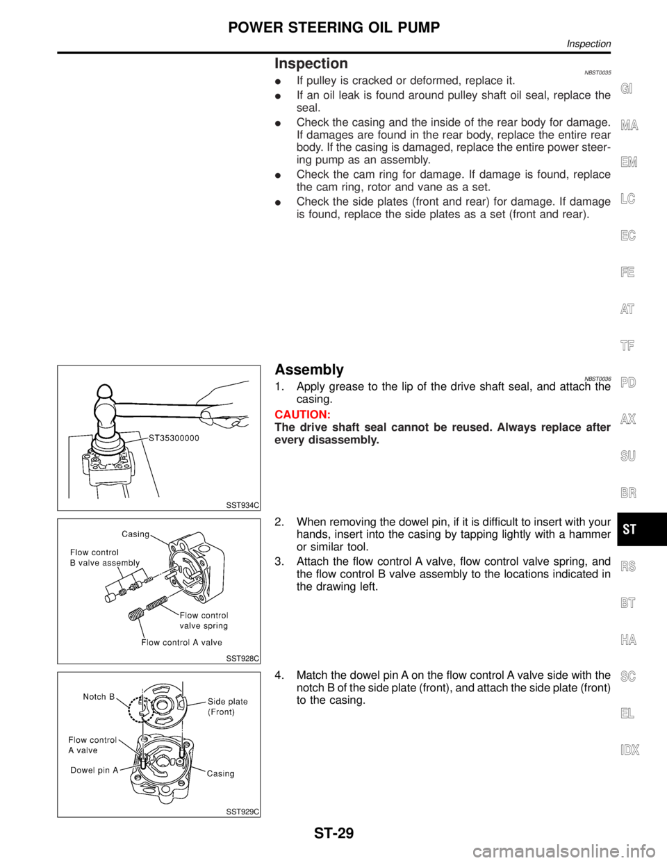
AssemblyNBST00361. Apply grease to the lip of the drive shaft seal, and attach the
casing.
CAUTION:
The drive shaft seal cannot be reused. Always replace after
every disassembly.
SST928C
2. When removing the dowel pin, if it is difficult to insert with your
hands, insert into the casing by tapping lightly with a hammer
or similar tool.
3. Attach the flow control A valve, flow control valve spring, and
the flow control B valve assembly to the locations indicated in
the drawing left.
SST929C
4. Match the dowel pin A on the flow control A valve side with the
notch B of the side plate (front), and attach the side plate (front)
to the casing.
GI
MA
EM
LC
EC
FE
AT
TF
PD
AX
SU
BR
RS
BT
HA
SC
EL
IDX
POWER STEERING OIL PUMP
Inspection
ST-29
Page 2247 of 2395
ALL-MODE 4WD TRANSFER BASIC CONTROLNBTF0007S01
SMT043D
HYDRAULIC CONTROL CIRCUITSNBTF0007S02
SMT040D
OUTLINENBTF0007S03All-mode 4WD transfer is controlled by the transfer control unit and
sensors.
If a malfunction occurs in the all-mode 4WD system, the 4WD
warning lamp lights up to indicate the system malfunction. There
are two ways to identify the cause of the malfunction.
1) Performing the self-diagnosis. (The 4WD warning lamp will
indicate what kind of malfunction has occurred by flickering.)
2) Performing diagnosis using CONSULT-II.
ALL-MODE 4WD SYSTEM
Control System (Cont'd)
TF-12
Page 2273 of 2395
Indicated items Display Conditions
4WD-mode2WD
4WD shift switchIn ª2WDº position
AUTO In ªAUTOº position
LOCK In ª4Hº position
4L In ª4LOº position
Front wheel speed 0 - 255 km/h (0 - 158 MPH) 0 km/h (vehicle at standstill)
Rear wheel speed 0 - 255 km/h (0 - 158 MPH) 0 km/h (vehicle at standstill)
Shift ACTR operating 1,
Shift activating monitor 1OFF During normal operation
ON During shifts from ª4Hº to ª4LOº position
Shift ACTR operating 2,
Shift activating monitor 2OFF During normal operation
ON During shifts from ª4LOº to ª4Hº position
4WD fail lamp OFF During normal operation
ONDuring 2-second period (after key switch turned to ªONº) or
when system is out of order
Shift ACTR position sensing
switch 1OFF 4WD shift switch is in a position other than ª4LOº.
ON 4WD shift switch in ª4LOº position
Shift ACTR position sensing
switch 2OFF 4WD shift switch in ª4LOº position
ON 4WD shift switch is in a position other than ª4LOº.
2WD indicator lamp OFF Engine at rest or system out of order
ON Except the above condition
AUTO indicator lamp
OFFEngine at rest during 2WD-mode operation or system out of
order
ON4WD shift switch in ª4LOº or ª4Hº position and A/T selector
lever in ªAUTOº position
LOCK indicator lamp
OFFEngine at rest and A/T selector lever in ªAUTOº position during
2WD-mode operation or system out of order
ON 4WD shift switch in ª4Hº or ª4LOº position
4L indicator lamp
OFFEngine at rest and A/T selector lever in ªAUTOº position during
2WD-mode operation or system out of order
ON 4WD shift switch in ª4LOº position
WORK SUPPORTNBTF0012S06PurposeNBTF0012S0601When there is no problem with transfer and 4WD system, follow-
ing symptoms in ªAUTOº mode may be claimed by a customer.
ITight corner braking symptom after accelerator (throttle) open-
ing (Note 1)
IVibration when accelerating on a low road (snow-covered or
icy road) (Note 2)
It is possible to deal with these symptoms by changing
ªCLUTCH FORCE RELEASE LIMIT VALUEº. However, be
careful when changing the values because it may adversely
affect driving performance.
NOTE:
1) When the accelerator is slightly open (approx. 1/8) or fully
closed after being opened. The tight corner braking symptom
during idle creep driving with accelerator fully closed cannot be
ON BOARD DIAGNOSTIC SYSTEM DESCRIPTION
Trouble Diagnosis with CONSULT-II (Cont'd)
TF-38
Page 2274 of 2395

solved by this method. Refer to SYMPTOM 8, TF-108.
2) A slight shock is felt at a few hertz as if it were being pushed
lightly from behind.
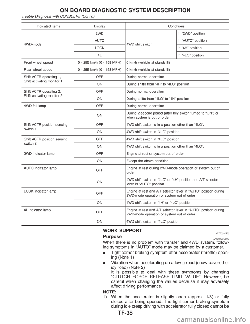
SMT962D
CONSULT-II Setting ProcedureNBTF0012S06021. Turn ignition switch to ªOFFº position.
2. Connect CONSULT-II to data link connector, which is located
in instrument lower panel on driver side.
3. Turn ignition switch to ªONº position.
4. Touch ªSTARTº.
5. Touch ªALL MODE 4WDº.
SMT965D
6. Touch ªWORK SUPPORTº.
SMT967D
7. Select WORK ITEM by touching ªCLUTCH/F RLS LIM ADJº.
NOTE:
ªSTART TORQ OFFSET ADJº is displayed, but the transfer does
not have this function.
CLUTCH FORCE RELEASE LIMIT ADJUSTMENTNBTF0012S071.2 kg-m: Tight corner braking symptom is alleviated. However,
vibration may occur when accelerating on a low road (icy road,
etc.).
0.3 kg-m: Initial set value
0.2 kg-m: Do not set to this value because the tight corner braking
symptom will get worse.
GI
MA
EM
LC
EC
FE
AT
PD
AX
SU
BR
ST
RS
BT
HA
SC
EL
IDX
ON BOARD DIAGNOSTIC SYSTEM DESCRIPTION
Trouble Diagnosis with CONSULT-II (Cont'd)
TF-39
Page 2276 of 2395
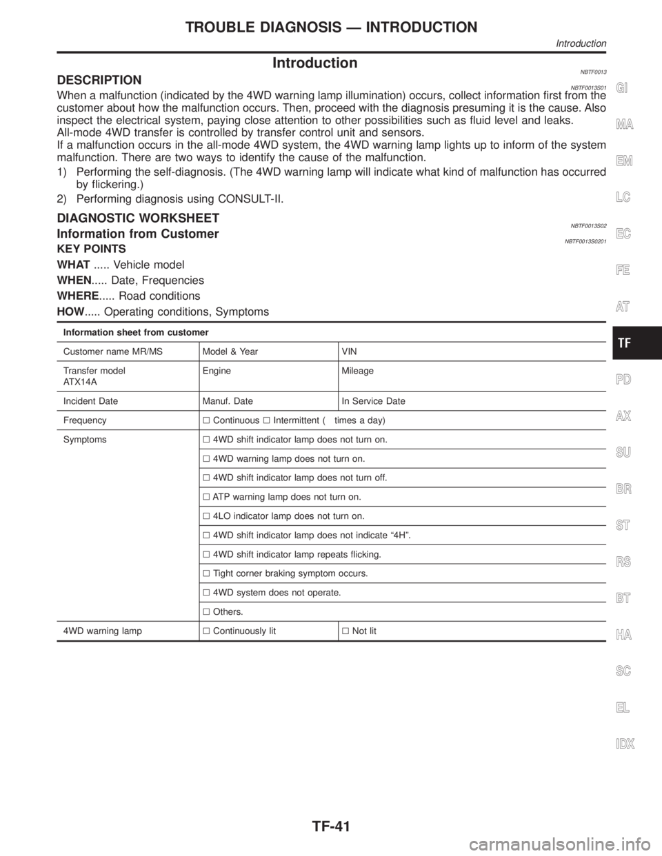
IntroductionNBTF0013DESCRIPTIONNBTF0013S01When a malfunction (indicated by the 4WD warning lamp illumination) occurs, collect information first from the
customer about how the malfunction occurs. Then, proceed with the diagnosis presuming it is the cause. Also
inspect the electrical system, paying close attention to other possibilities such as fluid level and leaks.
All-mode 4WD transfer is controlled by transfer control unit and sensors.
If a malfunction occurs in the all-mode 4WD system, the 4WD warning lamp lights up to inform of the system
malfunction. There are two ways to identify the cause of the malfunction.
1) Performing the self-diagnosis. (The 4WD warning lamp will indicate what kind of malfunction has occurred
by flickering.)
2) Performing diagnosis using CONSULT-II.
DIAGNOSTIC WORKSHEETNBTF0013S02Information from CustomerNBTF0013S0201KEY POINTS
WHAT..... Vehicle model
WHEN..... Date, Frequencies
WHERE..... Road conditions
HOW..... Operating conditions, Symptoms
Information sheet from customer
Customer name MR/MS Model & Year VIN
Transfer model
ATX14AEngine Mileage
Incident Date Manuf. Date In Service Date
FrequencylContinuouslIntermittent ( times a day)
Symptomsl4WD shift indicator lamp does not turn on.
l4WD warning lamp does not turn on.
l4WD shift indicator lamp does not turn off.
lATP warning lamp does not turn on.
l4LO indicator lamp does not turn on.
l4WD shift indicator lamp does not indicate ª4Hº.
l4WD shift indicator lamp repeats flicking.
lTight corner braking symptom occurs.
l4WD system does not operate.
lOthers.
4WD warning lamplContinuously litlNot lit
GI
MA
EM
LC
EC
FE
AT
PD
AX
SU
BR
ST
RS
BT
HA
SC
EL
IDX
TROUBLE DIAGNOSIS Ð INTRODUCTION
Introduction
TF-41