2001 INFINITI QX4 light
[x] Cancel search: lightPage 1572 of 2395
SEL685V
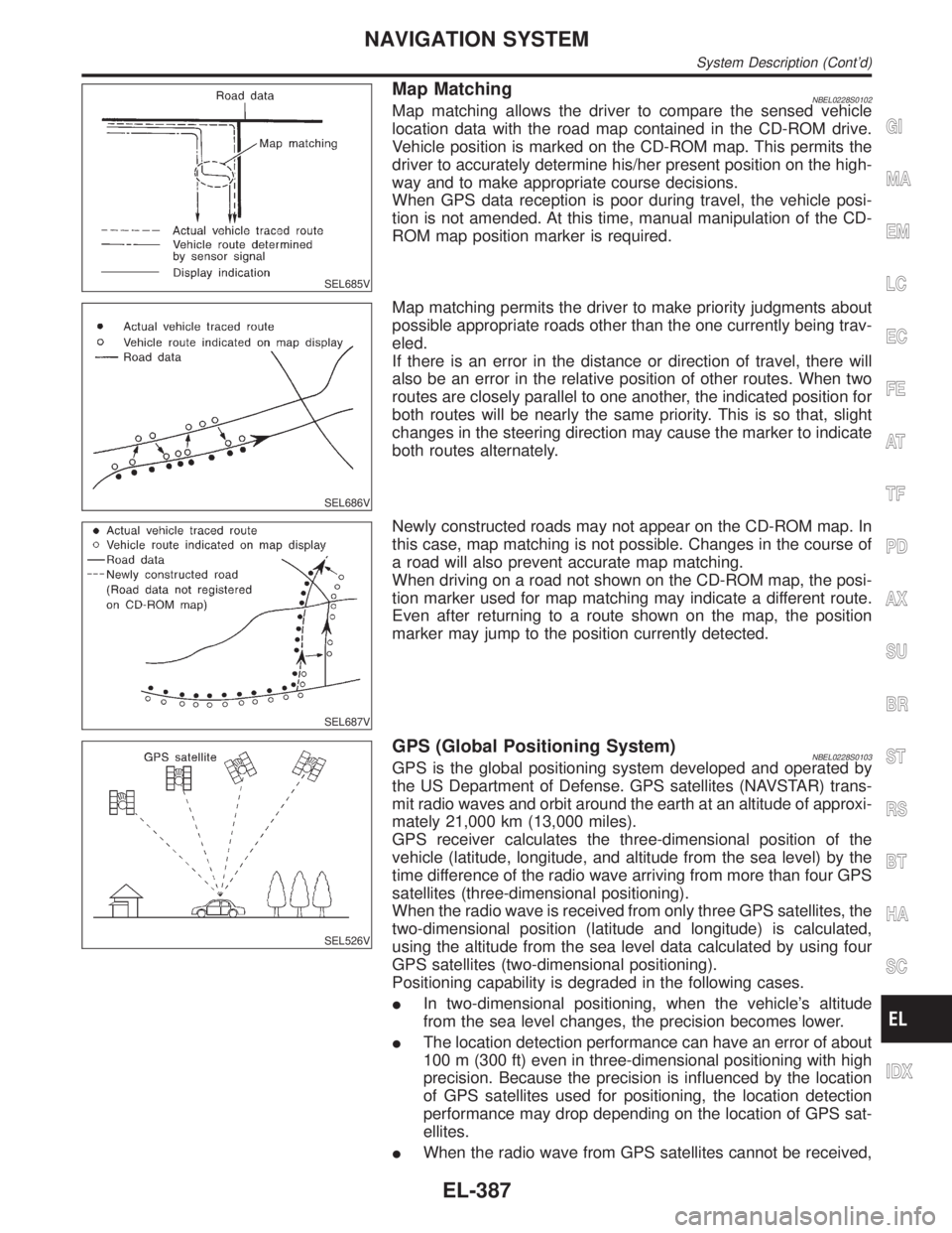
Map MatchingNBEL0228S0102Map matching allows the driver to compare the sensed vehicle
location data with the road map contained in the CD-ROM drive.
Vehicle position is marked on the CD-ROM map. This permits the
driver to accurately determine his/her present position on the high-
way and to make appropriate course decisions.
When GPS data reception is poor during travel, the vehicle posi-
tion is not amended. At this time, manual manipulation of the CD-
ROM map position marker is required.
SEL686V
Map matching permits the driver to make priority judgments about
possible appropriate roads other than the one currently being trav-
eled.
If there is an error in the distance or direction of travel, there will
also be an error in the relative position of other routes. When two
routes are closely parallel to one another, the indicated position for
both routes will be nearly the same priority. This is so that, slight
changes in the steering direction may cause the marker to indicate
both routes alternately.
SEL687V
Newly constructed roads may not appear on the CD-ROM map. In
this case, map matching is not possible. Changes in the course of
a road will also prevent accurate map matching.
When driving on a road not shown on the CD-ROM map, the posi-
tion marker used for map matching may indicate a different route.
Even after returning to a route shown on the map, the position
marker may jump to the position currently detected.
SEL526V
GPS (Global Positioning System)NBEL0228S0103GPS is the global positioning system developed and operated by
the US Department of Defense. GPS satellites (NAVSTAR) trans-
mit radio waves and orbit around the earth at an altitude of approxi-
mately 21,000 km (13,000 miles).
GPS receiver calculates the three-dimensional position of the
vehicle (latitude, longitude, and altitude from the sea level) by the
time difference of the radio wave arriving from more than four GPS
satellites (three-dimensional positioning).
When the radio wave is received from only three GPS satellites, the
two-dimensional position (latitude and longitude) is calculated,
using the altitude from the sea level data calculated by using four
GPS satellites (two-dimensional positioning).
Positioning capability is degraded in the following cases.
IIn two-dimensional positioning, when the vehicle's altitude
from the sea level changes, the precision becomes lower.
IThe location detection performance can have an error of about
100 m (300 ft) even in three-dimensional positioning with high
precision. Because the precision is influenced by the location
of GPS satellites used for positioning, the location detection
performance may drop depending on the location of GPS sat-
ellites.
IWhen the radio wave from GPS satellites cannot be received,
GI
MA
EM
LC
EC
FE
AT
TF
PD
AX
SU
BR
ST
RS
BT
HA
SC
IDX
NAVIGATION SYSTEM
System Description (Cont'd)
EL-387
Page 1589 of 2395
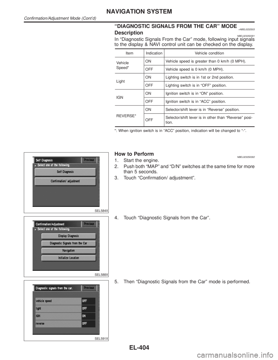
ªDIAGNOSTIC SIGNALS FROM THE CARº MODE=NBEL0232S03DescriptionNBEL0232S0301In ªDiagnostic Signals From the Carº mode, following input signals
to the display & NAVI control unit can be checked on the display.
Item Indication Vehicle condition
Vehicle
Speed*ON Vehicle speed is greater than 0 km/h (0 MPH).
OFF Vehicle speed is 0 km/h (0 MPH).
LightON Lighting switch is in 1st or 2nd position.
OFF Lighting switch is in ªOFFº position.
IGNON Ignition switch is in ªONº position.
OFF Ignition switch is in ªACCº position.
REVERSE*ON Selector/shift lever is in ªReverseº position.
OFFSelector/shift lever is in other than ªReverseº posi-
tion.
*: When ignition switch is in ªACCº position, indication will be changed to ª-º.
SEL584X
How to PerformNBEL0232S03021. Start the engine.
2. Push both ªMAPº and ªD/Nº switches at the same time for more
than 5 seconds.
3. Touch ªConfirmation/ adjustmentº.
SEL588X
4. Touch ªDiagnostic Signals from the Carº.
SEL591X
5. Then ªDiagnostic Signals from the Carº mode is performed.
NAVIGATION SYSTEM
Confirmation/Adjustment Mode (Cont'd)
EL-404
Page 1597 of 2395
SEL602X
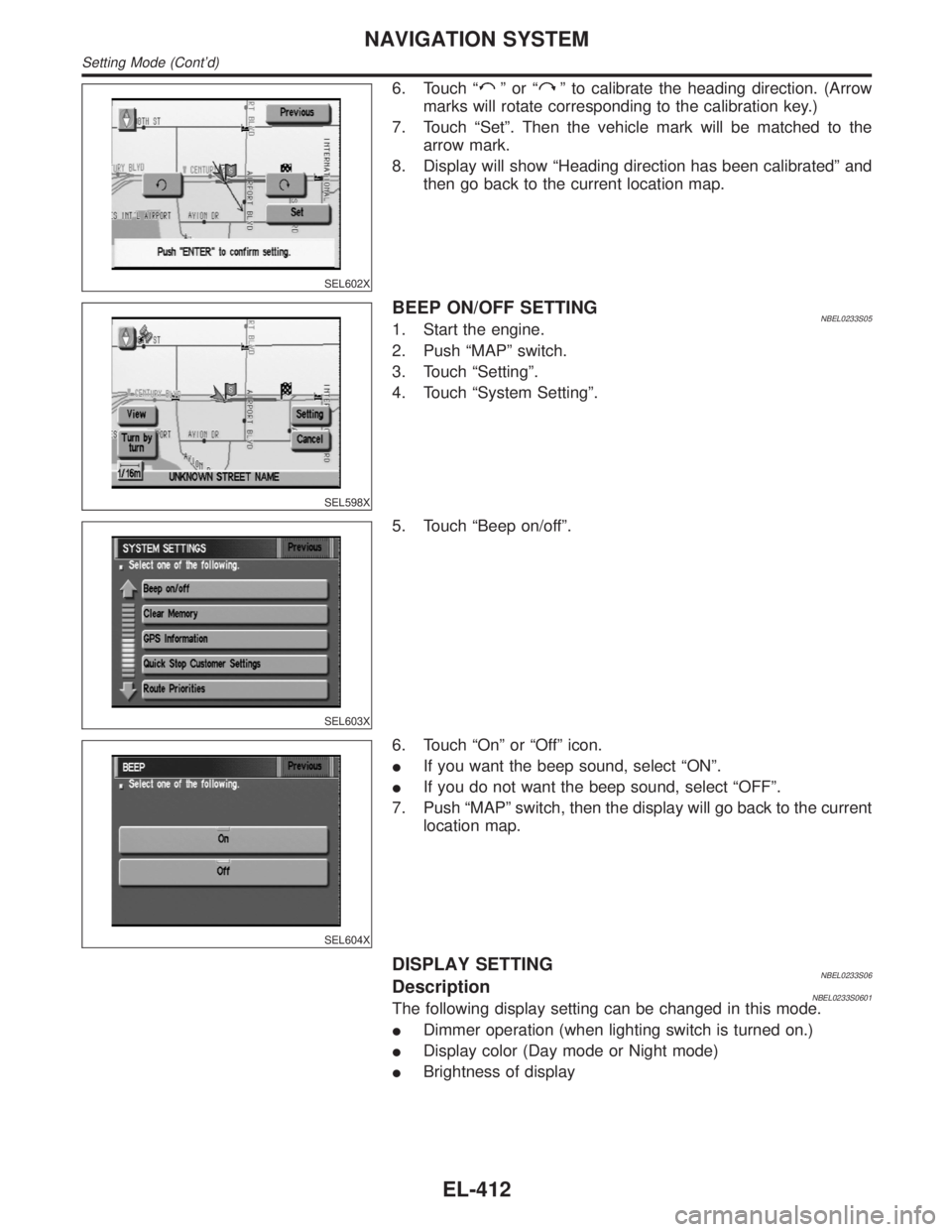
6. Touch ªºorªº to calibrate the heading direction. (Arrow
marks will rotate corresponding to the calibration key.)
7. Touch ªSetº. Then the vehicle mark will be matched to the
arrow mark.
8. Display will show ªHeading direction has been calibratedº and
then go back to the current location map.
SEL598X
BEEP ON/OFF SETTINGNBEL0233S051. Start the engine.
2. Push ªMAPº switch.
3. Touch ªSettingº.
4. Touch ªSystem Settingº.
SEL603X
5. Touch ªBeep on/offº.
SEL604X
6. Touch ªOnº or ªOffº icon.
IIf you want the beep sound, select ªONº.
IIf you do not want the beep sound, select ªOFFº.
7. Push ªMAPº switch, then the display will go back to the current
location map.
DISPLAY SETTINGNBEL0233S06DescriptionNBEL0233S0601The following display setting can be changed in this mode.
IDimmer operation (when lighting switch is turned on.)
IDisplay color (Day mode or Night mode)
IBrightness of display
NAVIGATION SYSTEM
Setting Mode (Cont'd)
EL-412
Page 1598 of 2395
SEL605X
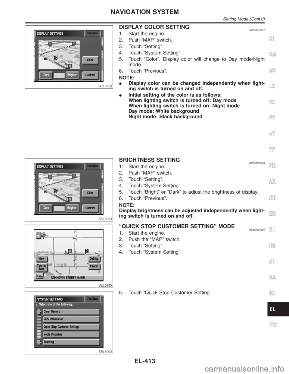
DISPLAY COLOR SETTINGNBEL0233S071. Start the engine.
2. Push ªMAPº switch.
3. Touch ªSettingº.
4. Touch ªSystem Settingº.
5. Touch ªColorº. Display color will change to Day mode/Night
mode.
6. Touch ªPreviousº.
NOTE:
IDisplay color can be changed independently when light-
ing switch is turned on and off.
IInitial setting of the color is as follows:
When lighting switch is turned off: Day mode
When lighting switch is turned on: Night mode
Day mode: White background
Night mode: Black background
SEL605X
BRIGHTNESS SETTINGNBEL0233S081. Start the engine.
2. Push ªMAPº switch.
3. Touch ªSettingº.
4. Touch ªSystem Settingº.
5. Touch ªBrightº or ªDarkº to adjust the brightness of display.
6. Touch ªPreviousº.
NOTE:
Display brightness can be adjusted independently when light-
ing switch is turned on and off.
SEL598X
ªQUICK STOP CUSTOMER SETTINGº MODENBEL0233S091. Start the engine.
2. Push the ªMAPº switch.
3. Touch ªSettingº.
4. Touch ªSystem Settingº.
SEL600X
5. Touch ªQuick Stop Customer Settingº.
GI
MA
EM
LC
EC
FE
AT
TF
PD
AX
SU
BR
ST
RS
BT
HA
SC
IDX
NAVIGATION SYSTEM
Setting Mode (Cont'd)
EL-413
Page 1602 of 2395
SEL611X
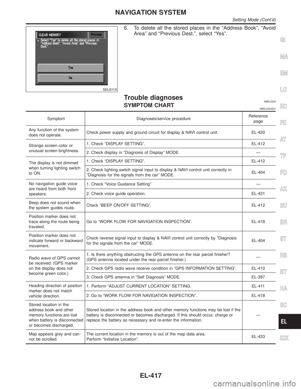
6. To delete all the stored places in the ªAddress Bookº, ªAvoid
Areaº and ªPrevious Dest.º, select ªYesº.
Trouble diagnosesNBEL0234SYMPTOM CHARTNBEL0234S01
Symptom Diagnoses/service procedureReference
page
Any function of the system
does not operate.Check power supply and ground circuit for display & NAVI control unit. EL-420
Strange screen color or
unusual screen brightness.1. Check ªDISPLAY SETTINGº. EL-412
2. Check display in ªDiagnosis of Displayº MODE. Ð
The display is not dimmed
when turning lighting switch
to ON.1. Check ªDISPLAY SETTINGº. EL-412
2. Check lighting switch signal input to display & NAVI control unit correctly in
ªDiagnosis for the signals from the carº MODE.EL-404
No navigation guide voice
are heard from both front
speakers.1. Check ªVoice Guidance Settingº. Ð
2. Check voice guide operation. EL-421
Beep does not sound when
the system guides route.Check ªBEEP ON/OFF SETTINGº. EL-412
Position marker does not
trace along the route being
traveled.Go to ªWORK FLOW FOR NAVIGATION INSPECTIONº. EL-418
Position marker does not
indicate forward or backward
movement.Check reverse signal input to display & NAVI control unit correctly by ªDiagnosis
for the signals from the carº MODE.EL-404
Radio wave of GPS cannot
be received. (GPS marker
on the display does not
become green color.)1. Is there anything obstructing the GPS antenna on the rear parcel finisher?
(GPS antenna located under the rear parcel finisher.)Ð
2. Check GPS radio wave receive condition in ªGPS INFORMATION SETTINGº. EL-410
3. Check GPS antenna in ªSelf Diagnosisº MODE. EL-397
Heading direction of position
marker does not match
vehicle direction.1. Perform ªADJUST CURRENT LOCATIONº SETTING. EL-411
2. Go to ªWORK FLOW FOR NAVIGATION INSPECTIONº. EL-418
Stored location in the
address book and other
memory functions are lost
when battery is disconnected
or becomes discharged.Stored location in the address book and other memory functions may be lost if the
battery is disconnected or becomes discharged. If this should occur, charge or
replace the battery as necessary and re-enter the information.Ð
Map appears grey and can-
not be scrolled.The current location in the memory is out of the map data area.
Perform ªInitialize Locationº.EL-433
GI
MA
EM
LC
EC
FE
AT
TF
PD
AX
SU
BR
ST
RS
BT
HA
SC
IDX
NAVIGATION SYSTEM
Setting Mode (Cont'd)
EL-417
Page 1614 of 2395
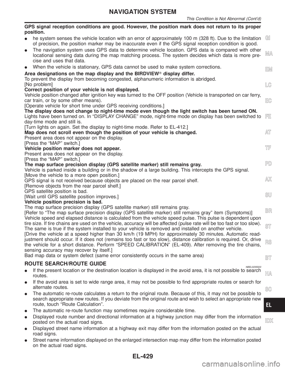
GPS signal reception conditions are good. However, the position mark does not return to its proper
position.
Ihe system senses the vehicle location with an error of approximately 100 m (328 ft). Due to the limitation
of precision, the position marker may be inaccurate even if the GPS signal reception condition is good.
IThe navigation system uses GPS data to determine vehicle location. GPS data is compared with other
locational sensing data during the map matching process. The system decides which data is more pre-
cise and uses that data.
IWhen the vehicle is stationary, GPS data cannot be used to make system corrections.
Area designations on the map display and the BIRDVIEWTdisplay differ.
To prevent the display from becoming congested, alphanumeric information is abridged.
[No problem]
Correct position of your vehicle is not displayed.
Vehicle position changed after ignition key was turned to the OFF position (Vehicle is transported on car ferry,
car train, or by some other means).
[Operate vehicle for short time under GPS receiving conditions.]
The display does not change to night-time mode even though the light switch has been turned ON.
Lights have been turned on. In ªDISPLAY CHANGEº mode, night-time mode on display has been switched to
day-time mode and still is.
[Turn lights on again. Set the display to night-time mode. Refer to EL-412.]
Map does not scroll even though the position of your vehicle is changed.
Present area does not appear on the display.
[Press the ªMAPº switch.]
Vehicle position marker does not appear.
Present area does not appear on the display.
[Press the ªMAPº switch.]
The map surface precision display (GPS satellite marker) still remains gray.
Vehicle is parked inside a building or in the shadow of a large building. This intercepts the GPS signal.
[Move the vehicle to a more open position.]
GPS signal is not received because objects are placed on the rear parcel shelf.
[Remove objects from the rear parcel shelf.]
GPS satellite position is bad.
[Wait until GPS satellite position improves.]
Vehicle position precision is bad.
The map surface precision display (GPS satellite marker) still remains gray.
[Refer to ªThe map surface precision display (GPS satellite marker) still remains grayº item (Symptoms)]
Vehicle speed and elapsed distance is calculated from the vehicle speed pulse. This pulse is dependent upon
tire size. If tire chains are used on the vehicle, accuracy will be affected (pulse rate will be too fast or too slow).
The same is true if the system installed to your vehicle is removed and installed on another vehicle.
[Drive the vehicle at a speed higher than 30 km/h (19 MPH) for approximately 30 minutes. Automatic read-
justment should occur. If it does not (remains too fast or too slow), distance calibration is required. Or, drive
the vehicle for a short distance. Perform ªSPEED CALIBRATIONº (EL-409). After removing the tire chains,
sensing accuracy may recover by itself.]
Bad map data or system defect (same error consistently occurs in the same area)
ROUTE SEARCH/ROUTE GUIDENBEL0235S03IIf the present location or the destination location is displayed in the avoid area, it is not possible to search
routes.
IIf the avoid area is set to wide range area, it may not be possible to find appropriate routes or search for
alternate routes.
IThe automatic re-route calculates a return to the original route. Because of this, it may not be possible to
search appropriate new routes. If you deviate from the original route and wish to select an appropriate new
route, touch ªRoute Calculationº.
IThe automatic re-route function may sometimes require considerable time.
IDisplayed route number and directional information at a highway junction may differ from the information
posted on the actual road signs.
IDisplayed street name information at a highway exit may differ from the information posted on the actual
road signs.
IStreet name information displayed on the enlarged intersection map may differ from the information posted
on the actual road signs.
GI
MA
EM
LC
EC
FE
AT
TF
PD
AX
SU
BR
ST
RS
BT
HA
SC
IDX
NAVIGATION SYSTEM
This Condition is Not Abnormal (Cont'd)
EL-429
Page 1616 of 2395
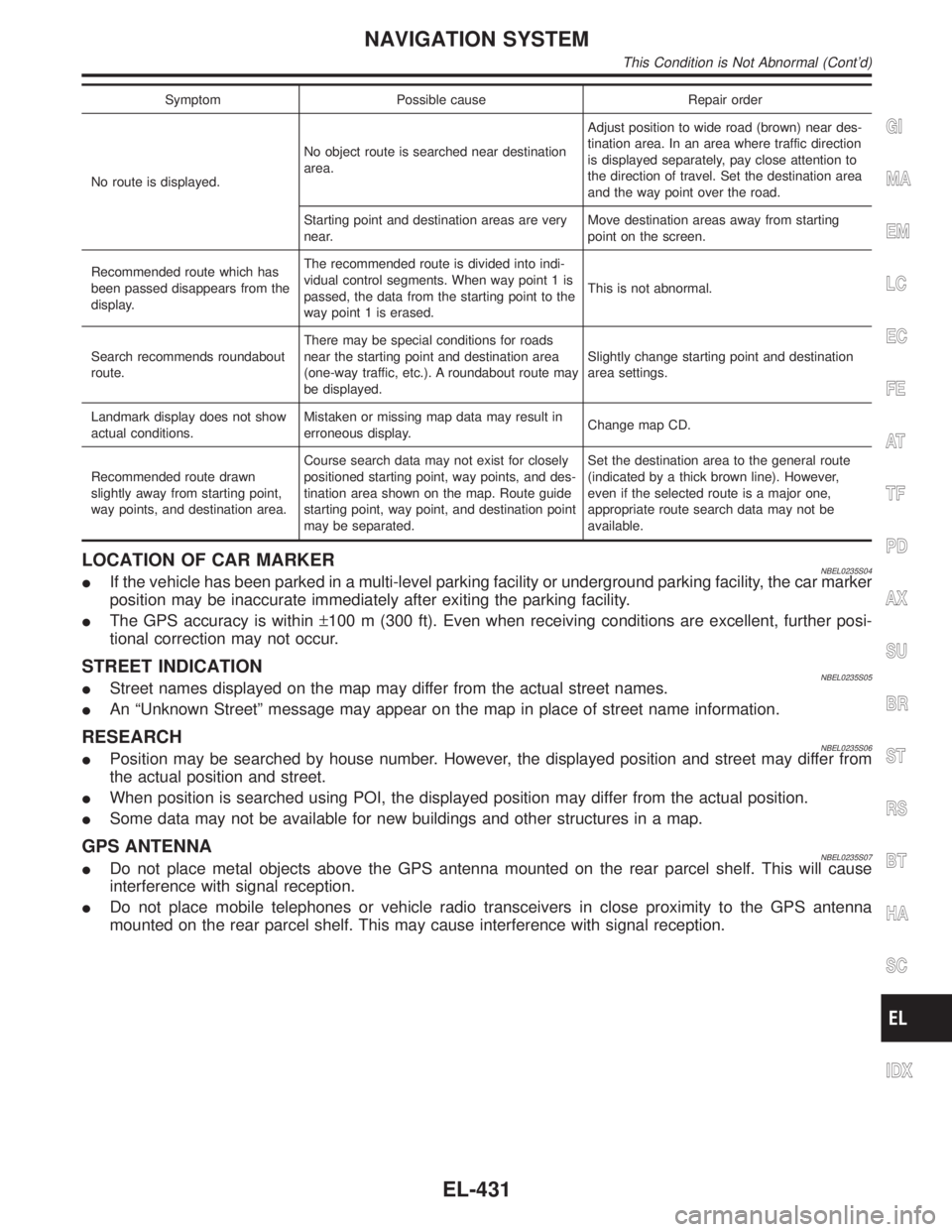
Symptom Possible cause Repair order
No route is displayed.No object route is searched near destination
area.Adjust position to wide road (brown) near des-
tination area. In an area where traffic direction
is displayed separately, pay close attention to
the direction of travel. Set the destination area
and the way point over the road.
Starting point and destination areas are very
near.Move destination areas away from starting
point on the screen.
Recommended route which has
been passed disappears from the
display.The recommended route is divided into indi-
vidual control segments. When way point 1 is
passed, the data from the starting point to the
way point 1 is erased.This is not abnormal.
Search recommends roundabout
route.There may be special conditions for roads
near the starting point and destination area
(one-way traffic, etc.). A roundabout route may
be displayed.Slightly change starting point and destination
area settings.
Landmark display does not show
actual conditions.Mistaken or missing map data may result in
erroneous display.Change map CD.
Recommended route drawn
slightly away from starting point,
way points, and destination area.Course search data may not exist for closely
positioned starting point, way points, and des-
tination area shown on the map. Route guide
starting point, way point, and destination point
may be separated.Set the destination area to the general route
(indicated by a thick brown line). However,
even if the selected route is a major one,
appropriate route search data may not be
available.
LOCATION OF CAR MARKERNBEL0235S04IIf the vehicle has been parked in a multi-level parking facility or underground parking facility, the car marker
position may be inaccurate immediately after exiting the parking facility.
IThe GPS accuracy is within±100 m (300 ft). Even when receiving conditions are excellent, further posi-
tional correction may not occur.
STREET INDICATIONNBEL0235S05IStreet names displayed on the map may differ from the actual street names.
IAn ªUnknown Streetº message may appear on the map in place of street name information.
RESEARCHNBEL0235S06IPosition may be searched by house number. However, the displayed position and street may differ from
the actual position and street.
IWhen position is searched using POI, the displayed position may differ from the actual position.
ISome data may not be available for new buildings and other structures in a map.
GPS ANTENNANBEL0235S07IDo not place metal objects above the GPS antenna mounted on the rear parcel shelf. This will cause
interference with signal reception.
IDo not place mobile telephones or vehicle radio transceivers in close proximity to the GPS antenna
mounted on the rear parcel shelf. This may cause interference with signal reception.
GI
MA
EM
LC
EC
FE
AT
TF
PD
AX
SU
BR
ST
RS
BT
HA
SC
IDX
NAVIGATION SYSTEM
This Condition is Not Abnormal (Cont'd)
EL-431
Page 1642 of 2395
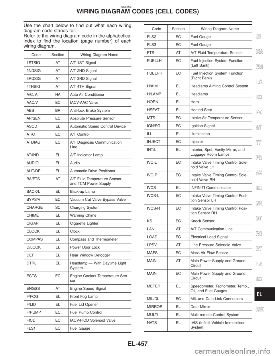
NBEL0145
Use the chart below to find out what each wiring
diagram code stands for.
Refer to the wiring diagram code in the alphabetical
index to find the location (page number) of each
wiring diagram.
Code Section Wiring Diagram Name
1STSIG AT A/T 1ST Signal
2NDSIG AT A/T 2ND Signal
3RDSIG AT A/T 3RD Signal
4THSIG AT A/T 4TH Signal
A/C, A HA Auto Air Conditioner
AAC/V EC IACV-AAC Valve
ABS BR Anti-lock Brake System
AP/SEN EC Absolute Pressure Sensor
ASCD EL Automatic Speed Control Device
AT/C EC A/T Control
ATDIAG EC A/T Diagnosis Communication
Line
AT/IND EL A/T Indicator Lamp
AUDIO EL Audio
AUT/DP EL Automatic Drive Positioner
BA/FTS AT A/T Fluid Temperature Sensor
and TCM Power Supply
BACK/L EL Back-up Lamp
BYPS/V EC Vacuum Cut Valve Bypass Valve
CHARGE SC Charging System
CHIME EL Warning Chime
CIGAR EL Cigarette Lighter
CLOCK EL Clock
COMPAS EL Compass and Thermometer
D/LOCK EL Power Door Lock
DEF EL Rear Window Defogger
DTRL EL Headlamp Ð With Daytime Light
System Ð
ECTS EC Engine Coolant Temperature Sen-
sor
ENGSS AT Engine Speed Signal
F/FOG EL Front Fog Lamp
F/LID EL Fuel Lid Opener
F/PUMP EC Fuel Pump Control
FICD EC IACV-FICD Solenoid Valve
FLS1 EC Fuel Gauge
Code Section Wiring Diagram Name
FLS2 EC Fuel Gauge
FLS3 EC Fuel Gauge
FTS AT A/T Fluid Temperature Sensor
FUELLH EC Fuel Injection System Function
(Left Bank)
FUELRH EC Fuel Injection System Function
(Right Bank)
H/AIM EL Headlamp Aiming Control System
H/LAMP EL Headlamp
HORN EL Horn
HSEAT EL Heated Seat
IATS EC Intake Air Temperature Sensor
IGN/SG EC Ignition Signal
ILL EL Illumination
INJECT EC Injector
INT/L EL Interior, Spot, Vanity Mirror, and
Luggage Room Lamps
IVC-L EC Intake Valve Timing Control Sole-
noid Valve LH
IVC-R EC Intake Valve Timing Control Sole-
noid Valve RH
IVCS EL INFINITI Communicator
IVCS-L EC Intake Valve Timing Control Posi-
tion Sensor LH
IVCS-R EC Intake Valve Timing Control Posi-
tion Sensor RH
KS EC Knock Sensor
LAN AT A/T Communication Line
LOAD EC Electrical Load Signal
LPSV AT Line Pressure Solenoid Valve
MAFS EC Mass Air Flow Sensor
MAIN AT Main Power Supply and Ground
Circuit
MAIN EC Main Power Supply and Ground
Circuit
METER EL Speedometer, Tachometer, Temp.,
Oil, and Fuel Gauges
MIL/DL EC MIL and Data Link Connectors
MIRROR EL Door Mirror
MULTI EL Multi-remote Control System
NATS EL IVIS (Infiniti Vehicle Immobiliser
System)
GI
MA
EM
LC
EC
FE
AT
TF
PD
AX
SU
BR
ST
RS
BT
HA
SC
IDX
WIRING DIAGRAM CODES (CELL CODES)
EL-457