Page 1317 of 2395
4 CHECK TAIL LAMP SWITCH GROUND CIRCUIT
1. Disconnect headlamp battery saver control unit connector.
2. Check continuity between headlamp battery saver control unit terminal 5, 13 and ground.
SEL379X
OK or NG
OK©Check headlamp battery saver control unit. Refer to EL-42.
NG©Check the following.
ILighting switch
IHarness for open or short between headlamp battery saver control unit terminal 5, 13
and lighting switch terminal 11
IHarness between lighting switch terminal 5 and ground
WARNING CHIME
Trouble Diagnoses (Cont'd)
EL-132
Page 1333 of 2395
Wiring Diagram Ð CIGAR ÐNBEL0156
MEL812L
CIGARETTE LIGHTER
Wiring Diagram Ð CIGAR Ð
EL-148
Page 1334 of 2395
MEL813L
GI
MA
EM
LC
EC
FE
AT
TF
PD
AX
SU
BR
ST
RS
BT
HA
SC
IDX
CIGARETTE LIGHTER
Wiring Diagram Ð CIGAR Ð (Cont'd)
EL-149
Page 1343 of 2395

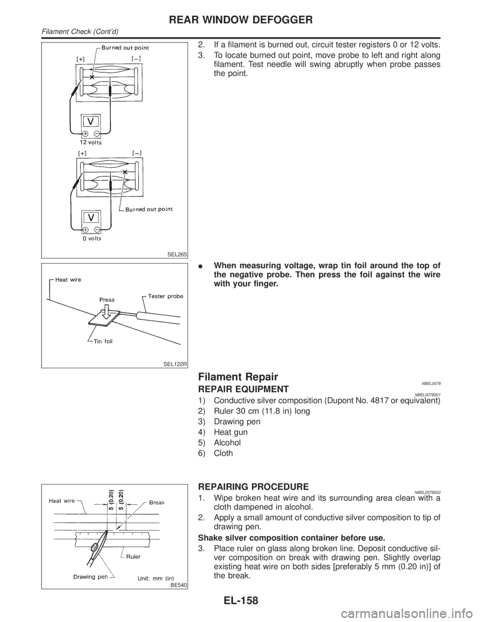
SEL265
2. If a filament is burned out, circuit tester registers 0 or 12 volts.
3. To locate burned out point, move probe to left and right along
filament. Test needle will swing abruptly when probe passes
the point.
SEL122R
IWhen measuring voltage, wrap tin foil around the top of
the negative probe. Then press the foil against the wire
with your finger.
Filament RepairNBEL0078REPAIR EQUIPMENTNBEL0078S011) Conductive silver composition (Dupont No. 4817 or equivalent)
2) Ruler 30 cm (11.8 in) long
3) Drawing pen
4) Heat gun
5) Alcohol
6) Cloth
BE540
REPAIRING PROCEDURENBEL0078S021. Wipe broken heat wire and its surrounding area clean with a
cloth dampened in alcohol.
2. Apply a small amount of conductive silver composition to tip of
drawing pen.
Shake silver composition container before use.
3. Place ruler on glass along broken line. Deposit conductive sil-
ver composition on break with drawing pen. Slightly overlap
existing heat wire on both sides [preferably 5 mm (0.20 in)] of
the break.
REAR WINDOW DEFOGGER
Filament Check (Cont'd)
EL-158
Page 1385 of 2395

2) End
After performing preliminary check, go to symptom chart
below.
Before starting trouble diagnoses below, perform preliminary
check, EL-199. Symptom numbers in the symptom chart cor-
respond with those of preliminary check.
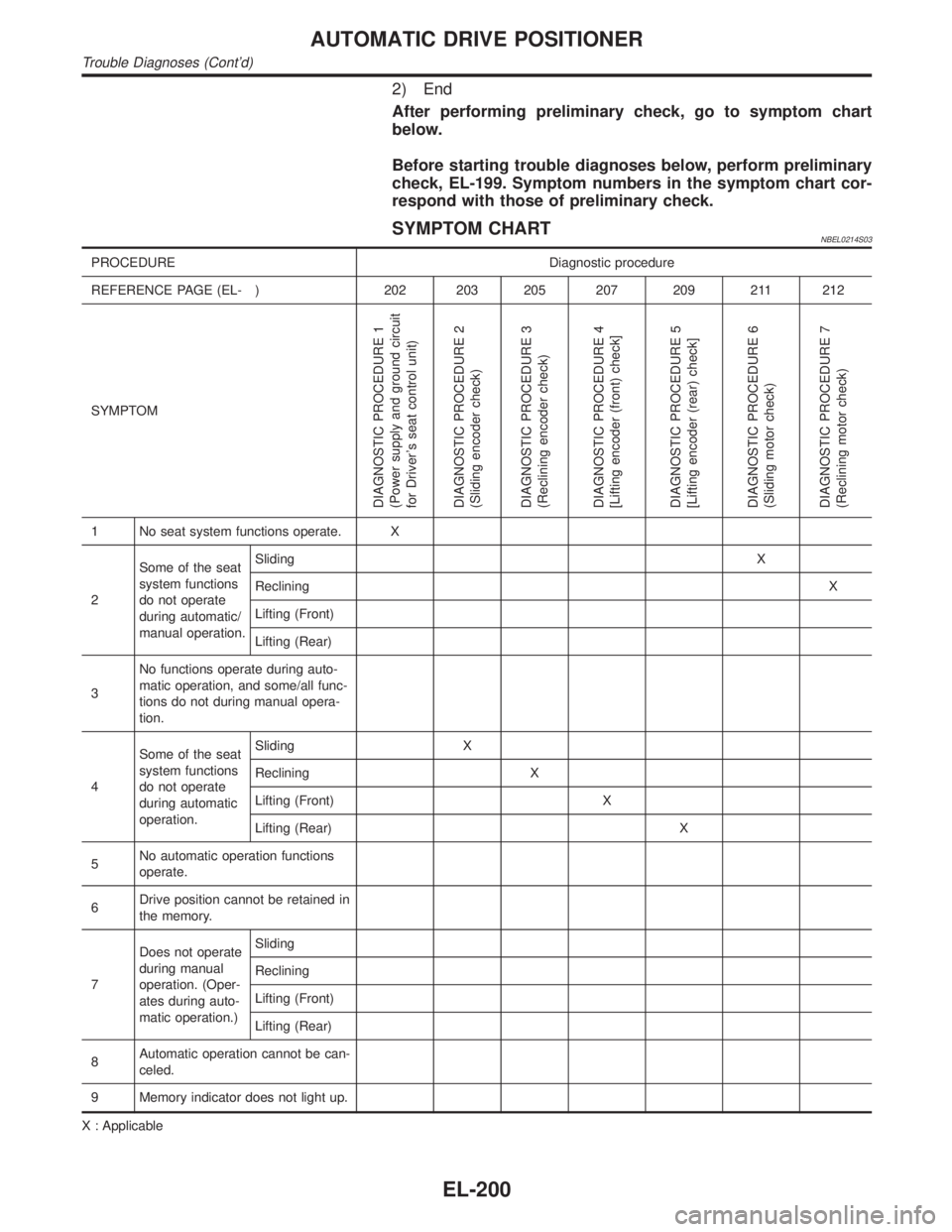
SYMPTOM CHARTNBEL0214S03
PROCEDURE Diagnostic procedure
REFERENCE PAGE (EL- ) 202 203 205 207 209 211 212
SYMPTOM
DIAGNOSTIC PROCEDURE 1
(Power supply and ground circuit
for Driver's seat control unit)
DIAGNOSTIC PROCEDURE 2
(Sliding encoder check)
DIAGNOSTIC PROCEDURE 3
(Reclining encoder check)
DIAGNOSTIC PROCEDURE 4
[Lifting encoder (front) check]
DIAGNOSTIC PROCEDURE 5
[Lifting encoder (rear) check]
DIAGNOSTIC PROCEDURE 6
(Sliding motor check)
DIAGNOSTIC PROCEDURE 7
(Reclining motor check)
1 No seat system functions operate. X
2Some of the seat
system functions
do not operate
during automatic/
manual operation.SlidingX
RecliningX
Lifting (Front)
Lifting (Rear)
3No functions operate during auto-
matic operation, and some/all func-
tions do not during manual opera-
tion.
4Some of the seat
system functions
do not operate
during automatic
operation.Sliding X
Reclining X
Lifting (Front) X
Lifting (Rear) X
5No automatic operation functions
operate.
6Drive position cannot be retained in
the memory.
7Does not operate
during manual
operation. (Oper-
ates during auto-
matic operation.)Sliding
Reclining
Lifting (Front)
Lifting (Rear)
8Automatic operation cannot be can-
celed.
9 Memory indicator does not light up.
X : Applicable
AUTOMATIC DRIVE POSITIONER
Trouble Diagnoses (Cont'd)
EL-200
Page 1386 of 2395
![INFINITI QX4 2001 Factory Service Manual PROCEDURE Diagnostic procedure
REFERENCE PAGE (EL- ) 213 214 215 216 217 220 220
SYMPTOM
DIAGNOSTIC PROCEDURE 8
[Lifting motor (front) check]
DIAGNOSTIC PROCEDURE 9
[Lifting motor (rear) check]
DIAGNO INFINITI QX4 2001 Factory Service Manual PROCEDURE Diagnostic procedure
REFERENCE PAGE (EL- ) 213 214 215 216 217 220 220
SYMPTOM
DIAGNOSTIC PROCEDURE 8
[Lifting motor (front) check]
DIAGNOSTIC PROCEDURE 9
[Lifting motor (rear) check]
DIAGNO](/manual-img/42/57027/w960_57027-1385.png)
PROCEDURE Diagnostic procedure
REFERENCE PAGE (EL- ) 213 214 215 216 217 220 220
SYMPTOM
DIAGNOSTIC PROCEDURE 8
[Lifting motor (front) check]
DIAGNOSTIC PROCEDURE 9
[Lifting motor (rear) check]
DIAGNOSTIC PROCEDURE 10
(Power seat switch check)
DIAGNOSTIC PROCEDURE 11
(Cancel switch check)
DIAGNOSTIC PROCEDURE 12
(Key, park position, door switch
and vehicle speed sensor check)
DIAGNOSTIC PROCEDURE 13
(Seat memory switch check)
DIAGNOSTIC PROCEDURE 14
(Memory indicator check)
1 No seat system functions operate.
2Some of the seat
system functions
do not operate
during automatic/
manual operation.Sliding
Reclining
Lifting (Front) X
Lifting (Rear) X
3No functions operate during auto-
matic operation, and some/all func-
tions do not during manual opera-
tion.XX
(ACC, ON
START
signal)
4Some of the seat
system functions
do not operate
during automatic
operation.Sliding
Reclining
Lifting (Front)
Lifting (Rear)
5No automatic operation functions
operate.XX
6Drive position cannot be retained in
the memory.X
(IGN ON
signal)X
7Does not operate
during manual
operation. (Oper-
ates during auto-
matic operation.)Sliding X
Reclining X
Lifting (Front) X
Lifting (Rear) X
8Automatic operation cannot be can-
celed.X
9 Memory indicator does not light up.X
X : Applicable
GI
MA
EM
LC
EC
FE
AT
TF
PD
AX
SU
BR
ST
RS
BT
HA
SC
IDX
AUTOMATIC DRIVE POSITIONER
Trouble Diagnoses (Cont'd)
EL-201
Page 1503 of 2395
THEFT WARNING HEADLAMP ALARM CHECK=NBEL0123S10
1 CHECK THEFT WARNING HEADLAMP ALARM OPERATION
1. Disconnect smart entrance control unit connector.
2. Apply ground to smart entrance control unit terminal 4.
SEL570X
Refer to wiring diagram in EL-304.
OK or NG
OK©Headlamp alarm is OK.
NG©GO TO 2.
2 CHECK HEADLAMP OPERATION
Does headlamp come on when turning lighting switch ªONº?
Ye s©Check harness for open or short between headlamp relay and smart entrance control
unit.
No©Check headlamp system. Refer to ªHEADLAMPº.
THEFT WARNING SYSTEM
Trouble Diagnoses (Cont'd)
EL-318
Page 1504 of 2395

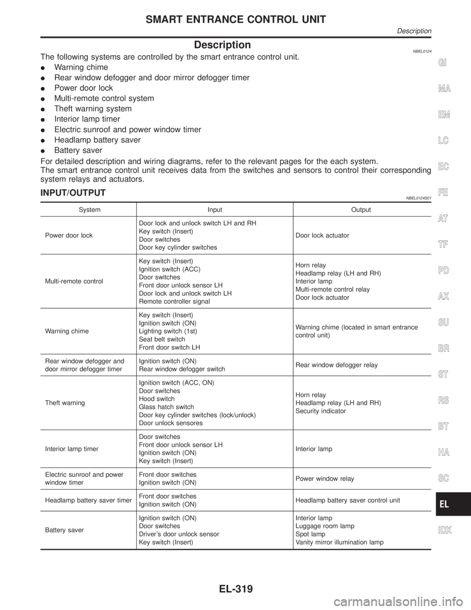
DescriptionNBEL0124The following systems are controlled by the smart entrance control unit.
IWarning chime
IRear window defogger and door mirror defogger timer
IPower door lock
IMulti-remote control system
ITheft warning system
IInterior lamp timer
IElectric sunroof and power window timer
IHeadlamp battery saver
IBattery saver
For detailed description and wiring diagrams, refer to the relevant pages for the each system.
The smart entrance control unit receives data from the switches and sensors to control their corresponding
system relays and actuators.
INPUT/OUTPUTNBEL0124S01
System Input Output
Power door lockDoor lock and unlock switch LH and RH
Key switch (Insert)
Door switches
Door key cylinder switchesDoor lock actuator
Multi-remote controlKey switch (Insert)
Ignition switch (ACC)
Door switches
Front door unlock sensor LH
Door lock and unlock switch LH
Remote controller signalHorn relay
Headlamp relay (LH and RH)
Interior lamp
Multi-remote control relay
Door lock actuator
Warning chimeKey switch (Insert)
Ignition switch (ON)
Lighting switch (1st)
Seat belt switch
Front door switch LHWarning chime (located in smart entrance
control unit)
Rear window defogger and
door mirror defogger timerIgnition switch (ON)
Rear window defogger switchRear window defogger relay
Theft warningIgnition switch (ACC, ON)
Door switches
Hood switch
Glass hatch switch
Door key cylinder switches (lock/unlock)
Door unlock sensoresHorn relay
Headlamp relay (LH and RH)
Security indicator
Interior lamp timerDoor switches
Front door unlock sensor LH
Ignition switch (ON)
Key switch (Insert)Interior lamp
Electric sunroof and power
window timerFront door switches
Ignition switch (ON)Power window relay
Headlamp battery saver timerFront door switches
Ignition switch (ON)Headlamp battery saver control unit
Battery saverIgnition switch (ON)
Door switches
Driver's door unlock sensor
Key switch (Insert)Interior lamp
Luggage room lamp
Spot lamp
Vanity mirror illumination lamp
GI
MA
EM
LC
EC
FE
AT
TF
PD
AX
SU
BR
ST
RS
BT
HA
SC
IDX
SMART ENTRANCE CONTROL UNIT
Description
EL-319