2001 DODGE RAM wheel bolt torque
[x] Cancel search: wheel bolt torquePage 1634 of 2889

INSTALLATION
(1) Align reference marks and install pitman arm.
(2) Install the lock washer and retaining nut on
the pitman shaft and tighten nut to 251 N´m (185 ft.
lbs.).
(3) Install drag link to the pitman arm. Install the
nut and tighten to 108 N´m (80 ft. lbs.).
(4) Install drag link to the right steering knuckle.
Install the nut and tighten to 88 N´m (65 ft. lbs.).
(5) Install tie rod to the left steering knuckle and
drag link. Install the nuts and tighten to 108 N´m
(80 ft. lbs.).(6) Install steering damper on the axle. Tighten
nut to 95 N´m (75 ft. lbs.).
(7) Install steering damper on the tie rod. Tighten
nut to 81 N´m (60 ft. lbs.).
(8) Remove the supports and lower the vehicle to
the surface. Center steering wheel and adjust toe,
refer to Group 2 Suspension.
(9) After adjustment tighten tie rod adjustment
sleeve clamp bolts to 61 N´m (45 ft. lbs.).
NOTE: Position the clamp on the sleeve so retaining
bolt is located on the bottom side of the sleeve.
SPECIFICATIONS
TORQUE CHART
TORQUE SPECIFICATIONS
DESCRIPTION N´m Ft. Lbs. In. Lbs.
Pitman Arm
Gear Shaft251 185 Ð
Drag Link
Pitman Arm108 80 Ð
Drag Link
Tie Rod88 65 Ð
Drag Link
Adjuster Clamp61 45 Ð
Tie Rod End
Knuckle108 80 Ð
Tie Rod End
Adjuster Clamp61 45 Ð
Steering Damper
Axle95 70 Ð
Steering Damper
Tie Rod81 60 Ð
BR/BELINKAGE - 4WD 19 - 41
LINKAGE - 4WD (Continued)
Page 1717 of 2889
INSTALLATION
NOTE: If a new transmission is being installed, be
sure to use all components supplied with the new
transmission. For example, if a new shift tower is
supplied with the new transmission, do not re-use
the original shift tower.
Befor installation apply light coat of Mopar high
temperature bearing grease to contact surfaces of fol-
lowing components:
²input shaft splines.
²release bearing slide surface of front retainer.
²release bearing bore.
²release fork.
²release fork ball stud.
²propeller shaft slip yoke.
(1) Apply sealer to threads of bottom PTO cover
bolt and install bolt in case.
(2) Mount transmission on jack and position trans-
mission under vehicle.
(3) Raise transmission until input shaft is centered
in release bearing and clutch disc hub.
(4) Move transmission forward and start input
shaft in release bearing, clutch disc and pilot bush-
ing.
(5) Work transmission forward until seated against
clutch housing. Do not allow transmission to remain
unsupported after input shaft has entered clutch
disc.
(6) Install and tighten transmission-to-clutch hous-
ing bolts to 108 N´m (80 ft. lbs.).
(7) Install transmission mount on transmission or
rear crossmember.
(8) Install rear crossmember.
(9) Remove transmission jack and engine support
fixture.
(10) Position transmission harness wires in clips
on shift cover.
(11) Install clutch slave cylinder and install slave
cylinder shield, if equipped.
(12) Connect speed sensor and backup light switch
wires.
TWO WHEEL DRIVE
(1) Fill transmission with recommended lubricant.
Correct fill level is bottom edge of fill plug hole.
(2) Align and install propeller shaft.
(3) Lower vehicle.
(4) Clean the mating surfaces of shift tower, isola-
tor plate, and shift cover with suitable wax and
grease remover.
(5) Apply Mopar Gasket Maker, or equivalent, to
the sealing surface of the shift cover. Do not over
apply sealant.(6) Install the isolator plate onto the shift cover,
metal side down.
(7) Install the shift tower onto the isolator plate.
No sealant is necessary between the shift tower and
the isolator plate.
(8) Verify that the shift tower, isolator plate, and
the shift tower bushings are properly aligned.
(9) Install the bolts to hold the shift tower to the
isolator plate and the shift cover. Tighten the shift
tower bolts to 10.2±11.25 N´m (7.5±8.3 ft. lbs.).
(10) Install the shift lever extension onto the shift
tower and lever assembly.
(11) Install shift boot and bezel.
(12) Connect battery negative cable.
FOUR WHEEL DRIVE
(1) Install transfer case shift mechanism on trans-
mission.
(2) Install transfer case on transmission jack.
Secure transfer case to jack with safety chains.
(3) Raise jack and align transfer case input gear
with transmission mainshaft.
(4) Move transfer case forward and seat it on
adapter.
(5) Install and tighten transfer case attaching
nuts. Tighten nuts to 41-47 N´m (30-35 ft. lbs.) if
case has 3/8 studs, or 30-41 N´m (22-30 ft. lbs.) if
case has 5/16 studs.
(6) Install transfer case shift mechanism to side of
transfer case.
(7) Connect transfer case shift lever to range lever
on transfer case.
(8) Align and connect propeller shafts.
(9) Fill transmission with required lubricant.
Check lubricant level in transfer case and add lubri-
cant if necessary.
(10) Install transfer case skid plate, if equipped,
and crossmember. Tighten attaching bolts/nuts to 41
N´m (30 ft. lbs.) torque.
(11) Install exhaust system components.
(12) Lower vehicle.
(13) Clean the mating surfaces of shift tower, iso-
lator plate, and shift cover with suitable wax and
grease remover.
(14) Apply Mopar Gasket Maker, or equivalent, to
the sealing surface of the shift cover. Do not over
apply sealant.
(15) Install the isolator plate onto the shift cover,
metal side down.
(16) Install the shift tower onto the isolator plate.
No sealant is necessary between the shift tower and
the isolator plate.
(17) Verify that the shift tower, isolator plate, and
the shift tower bushings are properly aligned.
21 - 82 MANUAL - NV4500BR/BE
MANUAL - NV4500 (Continued)
Page 1761 of 2889
(5) Clean the mating surfaces of shift tower and
isolator plate with suitable wax and grease remover.
(6) Apply Mopar Gasket Maker or equivalent to
sealing surface of the transmission case. Do not over
apply sealant.
(7) Install isolator plate onto the transmission case
metal side down.
(8) Install shift tower onto the isolator plate. No
sealant is necessary between the shift tower and top
of isolator plate.
(9) Verify that the shift tower, isolator plate and
the shift socket are properly aligned.
(10) Install bolts to hold the shift tower to the iso-
lator plate and the transmission case. Tighten bolts
to 10.2±11.25 N´m (7.5±8.3 ft. lbs.).
(11) Install shift boot and bezel.
(12) Connect battery negative cable.
FOUR WHEEL DRIVE
(1) Install and secure transfer case on the trans-
mission jack.
(2) Raise and align transfer case input gear with
transmission mainshaft.
(3) Move transfer case forward and seat it on
adapter.
(4) Install and tighten transfer case mounting nuts
to 41-47 N´m (30-35 ft. lbs.) if case has 3/8 studs. If
case has 5/16 studs tighten to 30-41 N´m (22-30 ft.
lbs.).
(5) Connect transfer case shift lever to range lever
on transfer case.(6) Install propeller shafts with reference marks
aligned.
(7) Fill transmission with required lubricant.
Check lubricant level in transfer case and add lubri-
cant if necessary.
(8) Install transfer case skid plate, if equipped,
and crossmember. Tighten attaching bolts/nuts to 41
N´m (30 ft. lbs.).
(9) Install exhaust system components.
(10) Remove support and lower vehicle.
(11) Shift transmission into third gear.
(12) Clean the mating surfaces of shift tower, iso-
lator plate, and transmission case with suitable wax
and grease remover.
(13) Apply Mopar Gasket Maker or equivalent to
the sealing surface of the transmission case. Do not
over apply sealant.
(14) Install isolator plate onto the transmission
case, metal side down.
(15) Install shift tower onto the isolator plate. No
sealant is necessary between the shift tower and top
of isolator plate.
(16) Verify that the shift tower, isolator plate and
the shift tower bushings are properly aligned.
(17) Install the bolts to hold the shift tower to the
isolator plate and the transmission case. Tighten the
shift tower bolts to 10.2±11.25 N´m (7.5±8.3 ft. lbs.).
(18) Install shift lever boot and bezel.
(19) Connect battery negative cable.
SPECIFICATIONS
SPECIFICATIONS - NV5600
TORQUE SPECIFICATIONS
DESCRIPTION N´m Ft. Lbs. In. Lbs.
Plug, Crossover Cam and
Detent48 35 -
Bolt, Input Retainer 28 20 -
Bolt, 5-6 Crossover Bracket 28 20 -
Bolt, Clutch Housing 48 35 -
Bolt, Extension/Adapter Housing 48 35 -
Bolt, Shift Tower 9 7 80
Switch, Back-up Lamp 28 20 -
Bolt, Shift Blocker 55 41 -
Bolt, PTO Cover 40 30 -
Pivot, Clutch Release Lever 22 16 -
Plug, Fill 30 22 -
Nut, Output Shaft 339 250 -
21 - 126 MANUAL - NV5600BR/BE
MANUAL - NV5600 (Continued)
Page 1895 of 2889
OPERATION
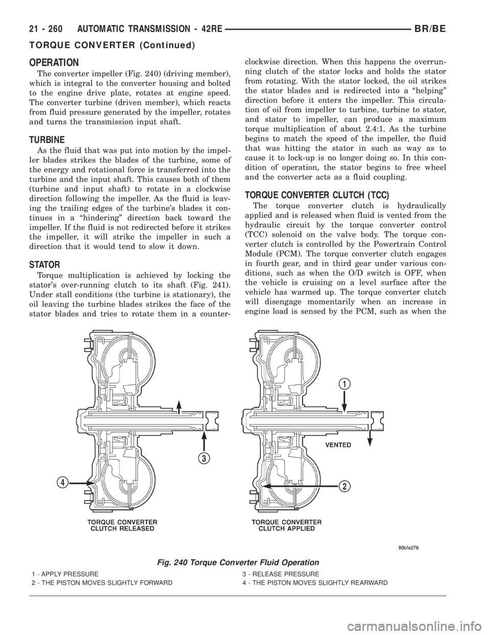
The converter impeller (Fig. 240) (driving member),
which is integral to the converter housing and bolted
to the engine drive plate, rotates at engine speed.
The converter turbine (driven member), which reacts
from fluid pressure generated by the impeller, rotates
and turns the transmission input shaft.
TURBINE
As the fluid that was put into motion by the impel-
ler blades strikes the blades of the turbine, some of
the energy and rotational force is transferred into the
turbine and the input shaft. This causes both of them
(turbine and input shaft) to rotate in a clockwise
direction following the impeller. As the fluid is leav-
ing the trailing edges of the turbine's blades it con-
tinues in a ªhinderingº direction back toward the
impeller. If the fluid is not redirected before it strikes
the impeller, it will strike the impeller in such a
direction that it would tend to slow it down.
STATOR
Torque multiplication is achieved by locking the
stator's over-running clutch to its shaft (Fig. 241).
Under stall conditions (the turbine is stationary), the
oil leaving the turbine blades strikes the face of the
stator blades and tries to rotate them in a counter-clockwise direction. When this happens the overrun-
ning clutch of the stator locks and holds the stator
from rotating. With the stator locked, the oil strikes
the stator blades and is redirected into a ªhelpingº
direction before it enters the impeller. This circula-
tion of oil from impeller to turbine, turbine to stator,
and stator to impeller, can produce a maximum
torque multiplication of about 2.4:1. As the turbine
begins to match the speed of the impeller, the fluid
that was hitting the stator in such as way as to
cause it to lock-up is no longer doing so. In this con-
dition of operation, the stator begins to free wheel
and the converter acts as a fluid coupling.
TORQUE CONVERTER CLUTCH (TCC)
The torque converter clutch is hydraulically
applied and is released when fluid is vented from the
hydraulic circuit by the torque converter control
(TCC) solenoid on the valve body. The torque con-
verter clutch is controlled by the Powertrain Control
Module (PCM). The torque converter clutch engages
in fourth gear, and in third gear under various con-
ditions, such as when the O/D switch is OFF, when
the vehicle is cruising on a level surface after the
vehicle has warmed up. The torque converter clutch
will disengage momentarily when an increase in
engine load is sensed by the PCM, such as when the
Fig. 240 Torque Converter Fluid Operation
1 - APPLY PRESSURE 3 - RELEASE PRESSURE
2 - THE PISTON MOVES SLIGHTLY FORWARD 4 - THE PISTON MOVES SLIGHTLY REARWARD
21 - 260 AUTOMATIC TRANSMISSION - 42REBR/BE
TORQUE CONVERTER (Continued)
Page 2239 of 2889
OPERATION
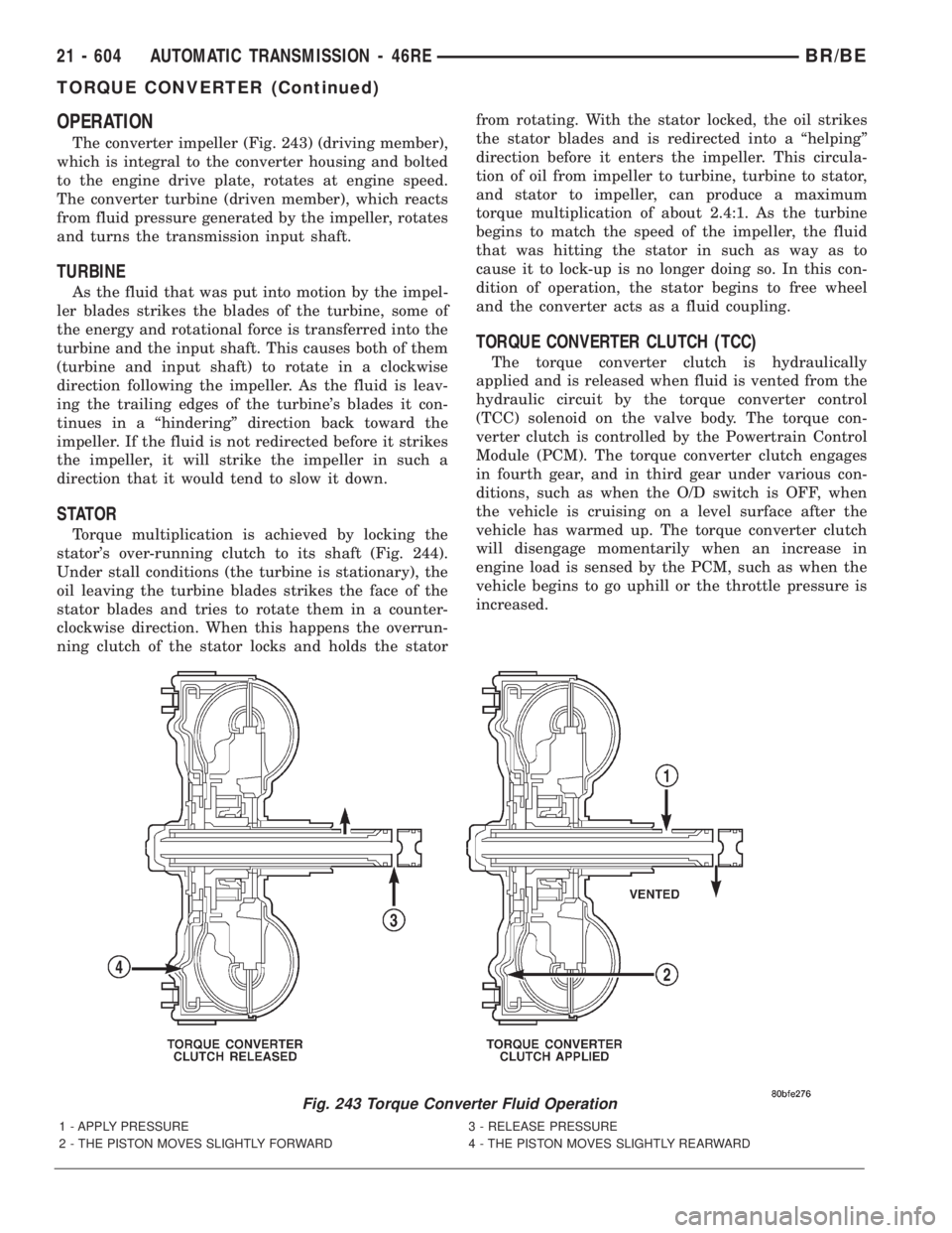
The converter impeller (Fig. 243) (driving member),
which is integral to the converter housing and bolted
to the engine drive plate, rotates at engine speed.
The converter turbine (driven member), which reacts
from fluid pressure generated by the impeller, rotates
and turns the transmission input shaft.
TURBINE
As the fluid that was put into motion by the impel-
ler blades strikes the blades of the turbine, some of
the energy and rotational force is transferred into the
turbine and the input shaft. This causes both of them
(turbine and input shaft) to rotate in a clockwise
direction following the impeller. As the fluid is leav-
ing the trailing edges of the turbine's blades it con-
tinues in a ªhinderingº direction back toward the
impeller. If the fluid is not redirected before it strikes
the impeller, it will strike the impeller in such a
direction that it would tend to slow it down.
STATOR
Torque multiplication is achieved by locking the
stator's over-running clutch to its shaft (Fig. 244).
Under stall conditions (the turbine is stationary), the
oil leaving the turbine blades strikes the face of the
stator blades and tries to rotate them in a counter-
clockwise direction. When this happens the overrun-
ning clutch of the stator locks and holds the statorfrom rotating. With the stator locked, the oil strikes
the stator blades and is redirected into a ªhelpingº
direction before it enters the impeller. This circula-
tion of oil from impeller to turbine, turbine to stator,
and stator to impeller, can produce a maximum
torque multiplication of about 2.4:1. As the turbine
begins to match the speed of the impeller, the fluid
that was hitting the stator in such as way as to
cause it to lock-up is no longer doing so. In this con-
dition of operation, the stator begins to free wheel
and the converter acts as a fluid coupling.
TORQUE CONVERTER CLUTCH (TCC)
The torque converter clutch is hydraulically
applied and is released when fluid is vented from the
hydraulic circuit by the torque converter control
(TCC) solenoid on the valve body. The torque con-
verter clutch is controlled by the Powertrain Control
Module (PCM). The torque converter clutch engages
in fourth gear, and in third gear under various con-
ditions, such as when the O/D switch is OFF, when
the vehicle is cruising on a level surface after the
vehicle has warmed up. The torque converter clutch
will disengage momentarily when an increase in
engine load is sensed by the PCM, such as when the
vehicle begins to go uphill or the throttle pressure is
increased.
Fig. 243 Torque Converter Fluid Operation
1 - APPLY PRESSURE 3 - RELEASE PRESSURE
2 - THE PISTON MOVES SLIGHTLY FORWARD 4 - THE PISTON MOVES SLIGHTLY REARWARD
21 - 604 AUTOMATIC TRANSMISSION - 46REBR/BE
TORQUE CONVERTER (Continued)
Page 2412 of 2889
OPERATION
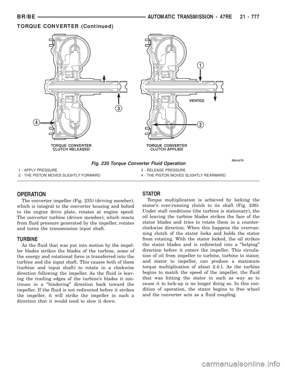
The converter impeller (Fig. 235) (driving member),
which is integral to the converter housing and bolted
to the engine drive plate, rotates at engine speed.
The converter turbine (driven member), which reacts
from fluid pressure generated by the impeller, rotates
and turns the transmission input shaft.
TURBINE
As the fluid that was put into motion by the impel-
ler blades strikes the blades of the turbine, some of
the energy and rotational force is transferred into the
turbine and the input shaft. This causes both of them
(turbine and input shaft) to rotate in a clockwise
direction following the impeller. As the fluid is leav-
ing the trailing edges of the turbine's blades it con-
tinues in a ªhinderingº direction back toward the
impeller. If the fluid is not redirected before it strikes
the impeller, it will strike the impeller in such a
direction that it would tend to slow it down.
STATOR
Torque multiplication is achieved by locking the
stator's over-running clutch to its shaft (Fig. 236).
Under stall conditions (the turbine is stationary), the
oil leaving the turbine blades strikes the face of the
stator blades and tries to rotate them in a counter-
clockwise direction. When this happens the overrun-
ning clutch of the stator locks and holds the stator
from rotating. With the stator locked, the oil strikes
the stator blades and is redirected into a ªhelpingº
direction before it enters the impeller. This circula-
tion of oil from impeller to turbine, turbine to stator,
and stator to impeller, can produce a maximum
torque multiplication of about 2.4:1. As the turbine
begins to match the speed of the impeller, the fluid
that was hitting the stator in such as way as to
cause it to lock-up is no longer doing so. In this con-
dition of operation, the stator begins to free wheel
and the converter acts as a fluid coupling.
Fig. 235 Torque Converter Fluid Operation
1 - APPLY PRESSURE 3 - RELEASE PRESSURE
2 - THE PISTON MOVES SLIGHTLY FORWARD 4 - THE PISTON MOVES SLIGHTLY REARWARD
BR/BEAUTOMATIC TRANSMISSION - 47RE 21 - 777
TORQUE CONVERTER (Continued)
Page 2571 of 2889
OPERATION
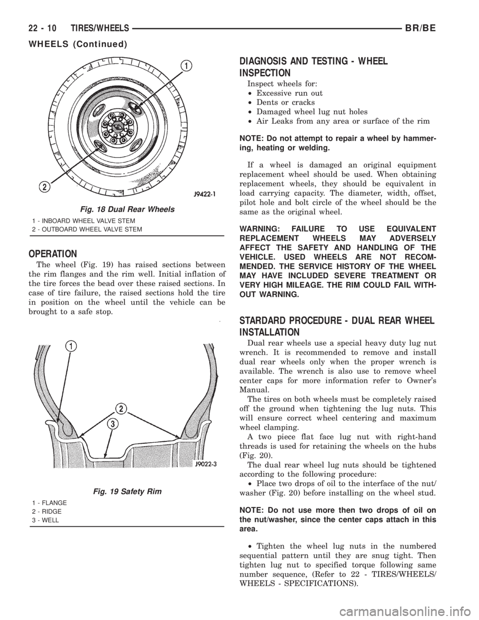
The wheel (Fig. 19) has raised sections between
the rim flanges and the rim well. Initial inflation of
the tire forces the bead over these raised sections. In
case of tire failure, the raised sections hold the tire
in position on the wheel until the vehicle can be
brought to a safe stop.
DIAGNOSIS AND TESTING - WHEEL
INSPECTION
Inspect wheels for:
²Excessive run out
²Dents or cracks
²Damaged wheel lug nut holes
²Air Leaks from any area or surface of the rim
NOTE: Do not attempt to repair a wheel by hammer-
ing, heating or welding.
If a wheel is damaged an original equipment
replacement wheel should be used. When obtaining
replacement wheels, they should be equivalent in
load carrying capacity. The diameter, width, offset,
pilot hole and bolt circle of the wheel should be the
same as the original wheel.
WARNING: FAILURE TO USE EQUIVALENT
REPLACEMENT WHEELS MAY ADVERSELY
AFFECT THE SAFETY AND HANDLING OF THE
VEHICLE. USED WHEELS ARE NOT RECOM-
MENDED. THE SERVICE HISTORY OF THE WHEEL
MAY HAVE INCLUDED SEVERE TREATMENT OR
VERY HIGH MILEAGE. THE RIM COULD FAIL WITH-
OUT WARNING.
STARDARD PROCEDURE - DUAL REAR WHEEL
INSTALLATION
Dual rear wheels use a special heavy duty lug nut
wrench. It is recommended to remove and install
dual rear wheels only when the proper wrench is
available. The wrench is also use to remove wheel
center caps for more information refer to Owner's
Manual.
The tires on both wheels must be completely raised
off the ground when tightening the lug nuts. This
will ensure correct wheel centering and maximum
wheel clamping.
A two piece flat face lug nut with right-hand
threads is used for retaining the wheels on the hubs
(Fig. 20).
The dual rear wheel lug nuts should be tightened
according to the following procedure:
²Place two drops of oil to the interface of the nut/
washer (Fig. 20) before installing on the wheel stud.
NOTE: Do not use more then two drops of oil on
the nut/washer, since the center caps attach in this
area.
²Tighten the wheel lug nuts in the numbered
sequential pattern until they are snug tight. Then
tighten lug nut to specified torque following same
number sequence, (Refer to 22 - TIRES/WHEELS/
WHEELS - SPECIFICATIONS).
Fig. 18 Dual Rear Wheels
1 - INBOARD WHEEL VALVE STEM
2 - OUTBOARD WHEEL VALVE STEM
Fig. 19 Safety Rim
1 - FLANGE
2 - RIDGE
3 - WELL
22 - 10 TIRES/WHEELSBR/BE
WHEELS (Continued)