2001 DODGE RAM wheel bolt torque
[x] Cancel search: wheel bolt torquePage 258 of 2889
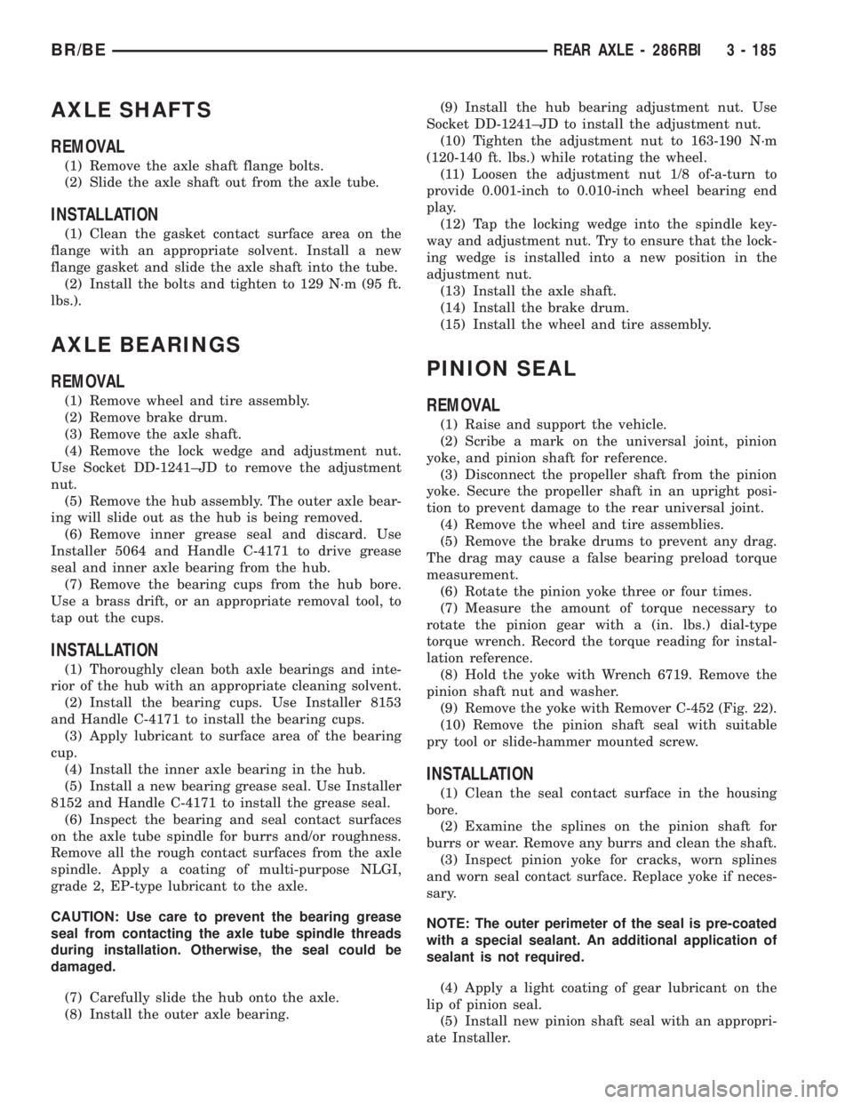
AXLE SHAFTS
REMOVAL
(1) Remove the axle shaft flange bolts.
(2) Slide the axle shaft out from the axle tube.
INSTALLATION
(1) Clean the gasket contact surface area on the
flange with an appropriate solvent. Install a new
flange gasket and slide the axle shaft into the tube.
(2) Install the bolts and tighten to 129 N´m (95 ft.
lbs.).
AXLE BEARINGS
REMOVAL
(1) Remove wheel and tire assembly.
(2) Remove brake drum.
(3) Remove the axle shaft.
(4) Remove the lock wedge and adjustment nut.
Use Socket DD-1241±JD to remove the adjustment
nut.
(5) Remove the hub assembly. The outer axle bear-
ing will slide out as the hub is being removed.
(6) Remove inner grease seal and discard. Use
Installer 5064 and Handle C-4171 to drive grease
seal and inner axle bearing from the hub.
(7) Remove the bearing cups from the hub bore.
Use a brass drift, or an appropriate removal tool, to
tap out the cups.
INSTALLATION
(1) Thoroughly clean both axle bearings and inte-
rior of the hub with an appropriate cleaning solvent.
(2) Install the bearing cups. Use Installer 8153
and Handle C-4171 to install the bearing cups.
(3) Apply lubricant to surface area of the bearing
cup.
(4) Install the inner axle bearing in the hub.
(5) Install a new bearing grease seal. Use Installer
8152 and Handle C-4171 to install the grease seal.
(6) Inspect the bearing and seal contact surfaces
on the axle tube spindle for burrs and/or roughness.
Remove all the rough contact surfaces from the axle
spindle. Apply a coating of multi-purpose NLGI,
grade 2, EP-type lubricant to the axle.
CAUTION: Use care to prevent the bearing grease
seal from contacting the axle tube spindle threads
during installation. Otherwise, the seal could be
damaged.
(7) Carefully slide the hub onto the axle.
(8) Install the outer axle bearing.(9) Install the hub bearing adjustment nut. Use
Socket DD-1241±JD to install the adjustment nut.
(10) Tighten the adjustment nut to 163-190 N´m
(120-140 ft. lbs.) while rotating the wheel.
(11) Loosen the adjustment nut 1/8 of-a-turn to
provide 0.001-inch to 0.010-inch wheel bearing end
play.
(12) Tap the locking wedge into the spindle key-
way and adjustment nut. Try to ensure that the lock-
ing wedge is installed into a new position in the
adjustment nut.
(13) Install the axle shaft.
(14) Install the brake drum.
(15) Install the wheel and tire assembly.
PINION SEAL
REMOVAL
(1) Raise and support the vehicle.
(2) Scribe a mark on the universal joint, pinion
yoke, and pinion shaft for reference.
(3) Disconnect the propeller shaft from the pinion
yoke. Secure the propeller shaft in an upright posi-
tion to prevent damage to the rear universal joint.
(4) Remove the wheel and tire assemblies.
(5) Remove the brake drums to prevent any drag.
The drag may cause a false bearing preload torque
measurement.
(6) Rotate the pinion yoke three or four times.
(7) Measure the amount of torque necessary to
rotate the pinion gear with a (in. lbs.) dial-type
torque wrench. Record the torque reading for instal-
lation reference.
(8) Hold the yoke with Wrench 6719. Remove the
pinion shaft nut and washer.
(9) Remove the yoke with Remover C-452 (Fig. 22).
(10) Remove the pinion shaft seal with suitable
pry tool or slide-hammer mounted screw.
INSTALLATION
(1) Clean the seal contact surface in the housing
bore.
(2) Examine the splines on the pinion shaft for
burrs or wear. Remove any burrs and clean the shaft.
(3) Inspect pinion yoke for cracks, worn splines
and worn seal contact surface. Replace yoke if neces-
sary.
NOTE: The outer perimeter of the seal is pre-coated
with a special sealant. An additional application of
sealant is not required.
(4) Apply a light coating of gear lubricant on the
lip of pinion seal.
(5) Install new pinion shaft seal with an appropri-
ate Installer.
BR/BEREAR AXLE - 286RBI 3 - 185
Page 263 of 2889
(14) Remove support and lower vehicle.
DIFFERENTIAL - TRAC-LOK
DIAGNOSIS AND TESTING - TRAC-LOKY
The most common problem is a chatter noise when
turning corners. Before removing a Trac-lokyunit
for repair, drain, flush and refill the axle with the
specified lubricant. A container of Mopar Trac-loky
Lubricant (friction modifier) should be added after
repair service or during a lubricant change.
After changing the lubricant, drive the vehicle and
make 10 to 12 slow, figure-eight turns. This maneu-
ver will pump lubricant through the clutches. This
will correct the condition in most instances. If the
chatter persists, clutch damage could have occurred.
DIFFERENTIAL TEST
The differential can be tested without removing the
differential case by measuring rotating torque. Make
sure brakes are not dragging during this measure-
ment.
(1) Place blocks in front and rear of both front
wheels.
(2) Raise one rear wheel until it is completely off
the ground.
(3) Engine off, transmission in neutral, and park-
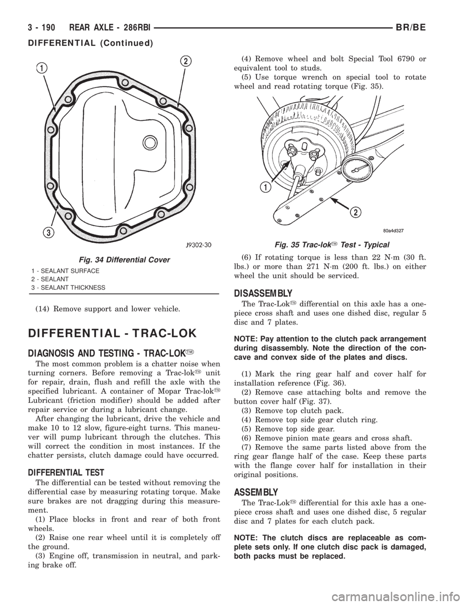
ing brake off.(4) Remove wheel and bolt Special Tool 6790 or
equivalent tool to studs.
(5) Use torque wrench on special tool to rotate
wheel and read rotating torque (Fig. 35).
(6) If rotating torque is less than 22 N´m (30 ft.
lbs.) or more than 271 N´m (200 ft. lbs.) on either
wheel the unit should be serviced.
DISASSEMBLY
The Trac-Lokydifferential on this axle has a one-
piece cross shaft and uses one dished disc, regular 5
disc and 7 plates.
NOTE: Pay attention to the clutch pack arrangement
during disassembly. Note the direction of the con-
cave and convex side of the plates and discs.
(1) Mark the ring gear half and cover half for
installation reference (Fig. 36).
(2) Remove case attaching bolts and remove the
button cover half (Fig. 37).
(3) Remove top clutch pack.
(4) Remove top side gear clutch ring.
(5) Remove top side gear.
(6) Remove pinion mate gears and cross shaft.
(7) Remove the same parts listed above from the
ring gear flange half of the case. Keep these parts
with the flange cover half for installation in their
original positions.
ASSEMBLY
The Trac-Lokydifferential for this axle has a one-
piece cross shaft and uses one dished disc, 5 regular
disc and 7 plates for each clutch pack.
NOTE: The clutch discs are replaceable as com-
plete sets only. If one clutch disc pack is damaged,
both packs must be replaced.
Fig. 34 Differential Cover
1 - SEALANT SURFACE
2 - SEALANT
3 - SEALANT THICKNESS
Fig. 35 Trac-lokYTest - Typical
3 - 190 REAR AXLE - 286RBIBR/BE
DIFFERENTIAL (Continued)
Page 274 of 2889
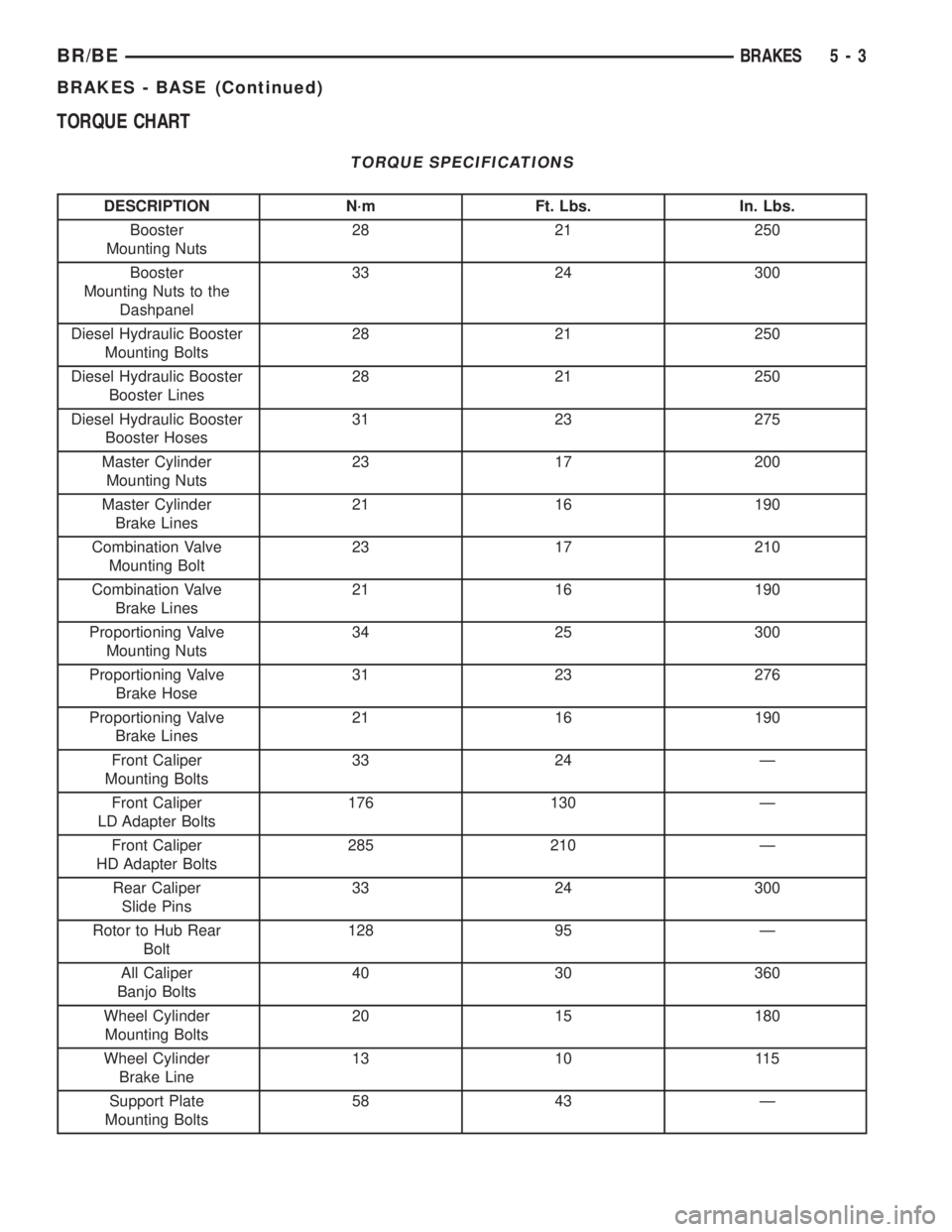
TORQUE CHART
TORQUE SPECIFICATIONS
DESCRIPTION N´m Ft. Lbs. In. Lbs.
Booster
Mounting Nuts28 21 250
Booster
Mounting Nuts to the
Dashpanel33 24 300
Diesel Hydraulic Booster
Mounting Bolts28 21 250
Diesel Hydraulic Booster
Booster Lines28 21 250
Diesel Hydraulic Booster
Booster Hoses31 23 275
Master Cylinder
Mounting Nuts23 17 200
Master Cylinder
Brake Lines21 16 190
Combination Valve
Mounting Bolt23 17 210
Combination Valve
Brake Lines21 16 190
Proportioning Valve
Mounting Nuts34 25 300
Proportioning Valve
Brake Hose31 23 276
Proportioning Valve
Brake Lines21 16 190
Front Caliper
Mounting Bolts33 24 Ð
Front Caliper
LD Adapter Bolts176 130 Ð
Front Caliper
HD Adapter Bolts285 210 Ð
Rear Caliper
Slide Pins33 24 300
Rotor to Hub Rear
Bolt128 95 Ð
All Caliper
Banjo Bolts40 30 360
Wheel Cylinder
Mounting Bolts20 15 180
Wheel Cylinder
Brake Line13 10 115
Support Plate
Mounting Bolts58 43 Ð
BR/BEBRAKES 5 - 3
BRAKES - BASE (Continued)
Page 303 of 2889
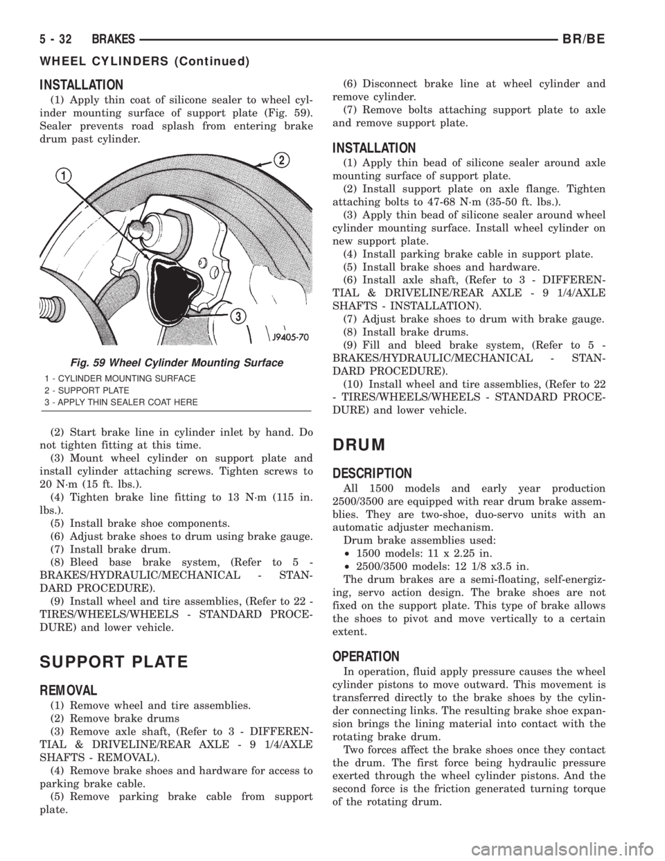
INSTALLATION
(1) Apply thin coat of silicone sealer to wheel cyl-
inder mounting surface of support plate (Fig. 59).
Sealer prevents road splash from entering brake
drum past cylinder.
(2) Start brake line in cylinder inlet by hand. Do
not tighten fitting at this time.
(3) Mount wheel cylinder on support plate and
install cylinder attaching screws. Tighten screws to
20 N´m (15 ft. lbs.).
(4) Tighten brake line fitting to 13 N´m (115 in.
lbs.).
(5) Install brake shoe components.
(6) Adjust brake shoes to drum using brake gauge.
(7) Install brake drum.
(8) Bleed base brake system, (Refer to 5 -
BRAKES/HYDRAULIC/MECHANICAL - STAN-
DARD PROCEDURE).
(9) Install wheel and tire assemblies, (Refer to 22 -
TIRES/WHEELS/WHEELS - STANDARD PROCE-
DURE) and lower vehicle.
SUPPORT PLATE
REMOVAL
(1) Remove wheel and tire assemblies.
(2) Remove brake drums
(3) Remove axle shaft, (Refer to 3 - DIFFEREN-
TIAL & DRIVELINE/REAR AXLE - 9 1/4/AXLE
SHAFTS - REMOVAL).
(4) Remove brake shoes and hardware for access to
parking brake cable.
(5) Remove parking brake cable from support
plate.(6) Disconnect brake line at wheel cylinder and
remove cylinder.
(7) Remove bolts attaching support plate to axle
and remove support plate.
INSTALLATION
(1) Apply thin bead of silicone sealer around axle
mounting surface of support plate.
(2) Install support plate on axle flange. Tighten
attaching bolts to 47-68 N´m (35-50 ft. lbs.).
(3) Apply thin bead of silicone sealer around wheel
cylinder mounting surface. Install wheel cylinder on
new support plate.
(4) Install parking brake cable in support plate.
(5) Install brake shoes and hardware.
(6) Install axle shaft, (Refer to 3 - DIFFEREN-
TIAL & DRIVELINE/REAR AXLE - 9 1/4/AXLE
SHAFTS - INSTALLATION).
(7) Adjust brake shoes to drum with brake gauge.
(8) Install brake drums.
(9) Fill and bleed brake system, (Refer to 5 -
BRAKES/HYDRAULIC/MECHANICAL - STAN-
DARD PROCEDURE).
(10) Install wheel and tire assemblies, (Refer to 22
- TIRES/WHEELS/WHEELS - STANDARD PROCE-
DURE) and lower vehicle.
DRUM
DESCRIPTION
All 1500 models and early year production
2500/3500 are equipped with rear drum brake assem-
blies. They are two-shoe, duo-servo units with an
automatic adjuster mechanism.
Drum brake assemblies used:
²1500 models: 11 x 2.25 in.
²2500/3500 models: 12 1/8 x3.5 in.
The drum brakes are a semi-floating, self-energiz-
ing, servo action design. The brake shoes are not
fixed on the support plate. This type of brake allows
the shoes to pivot and move vertically to a certain
extent.
OPERATION
In operation, fluid apply pressure causes the wheel
cylinder pistons to move outward. This movement is
transferred directly to the brake shoes by the cylin-
der connecting links. The resulting brake shoe expan-
sion brings the lining material into contact with the
rotating brake drum.
Two forces affect the brake shoes once they contact
the drum. The first force being hydraulic pressure
exerted through the wheel cylinder pistons. And the
second force is the friction generated turning torque
of the rotating drum.
Fig. 59 Wheel Cylinder Mounting Surface
1 - CYLINDER MOUNTING SURFACE
2 - SUPPORT PLATE
3 - APPLY THIN SEALER COAT HERE
5 - 32 BRAKESBR/BE
WHEEL CYLINDERS (Continued)
Page 314 of 2889
CLUTCH
TABLE OF CONTENTS
page page
CLUTCH
DESCRIPTION............................1
OPERATION.............................1
WARNING...............................2
DIAGNOSIS AND TESTING..................2
CLUTCH...............................2
SPECIFICATIONS.........................7
CLUTCH DISC
DESCRIPTION............................7
OPERATION.............................8
REMOVAL...............................8
INSTALLATION............................9
CLUTCH HOUSING
DIAGNOSIS AND TESTING.................11
CLUTCH HOUSING.....................11
REMOVAL..............................13
INSTALLATION...........................13
CLUTCH RELEASE BEARING
DESCRIPTION...........................14
OPERATION.............................14
REMOVAL..............................15
INSTALLATION...........................15
PRESSURE PLATE
DESCRIPTION...........................15OPERATION.............................16
FLYWHEEL
DESCRIPTION...........................16
OPERATION.............................16
DIAGNOSIS AND TESTING.................17
FLYWHEEL............................17
DISASSEMBLY...........................17
ASSEMBLY.............................17
PILOT BEARING
DESCRIPTION...........................17
OPERATION.............................18
REMOVAL..............................18
INSTALLATION...........................18
CLUTCH PEDAL
REMOVAL..............................18
INSTALLATION...........................19
LINKAGE
DESCRIPTION...........................19
OPERATION.............................20
REMOVAL..............................20
INSTALLATION...........................20
CLUTCH PEDAL POSITION SWITCH
DESCRIPTION...........................22
OPERATION.............................22
CLUTCH
DESCRIPTION
The clutch mechanism consists of a flywheel, a sin-
gle, dry-type disc, and a diaphragm style clutch cover
(Fig. 1). A hydraulic linkage is used to operate the
clutch release bearing and fork. The flywheel is
bolted to the rear flange of the crankshaft. The
clutch pressure plate is bolted to the flywheel with
the clutch disc located between these two compo-
nents. The clutch system provides the mechanical,
but still easily detachable, link between the engine
and the transmission. The system is designed to
ensure that the full torque output of the engine is
transfered to the transmission while isolating the
transmission from the engine firing pulses to mini-
mize concerns such as gear rattle.
OPERATION
Leverage, clamping force, and friction are what
make the clutch work. The disc serves as the friction
element and a diaphragm spring and pressure plate
provide the clamping force. The clutch pedal, hydrau-
lic linkage, release lever and bearing provide the
leverage.
The clutch master cylinder push rod is connected
to the clutch pedal. When the clutch pedal is
depressed, the slave cylinder is operated by the
clutch master cylinder mounted on the dash panel.
The release fork is actuated by the hydraulic slave
cylinder mounted on the transmission housing. The
release bearing is operated by a release fork pivoting
on a ball stud mounted in the transmission housing.
The release bearing then depresses the pressure
plate spring fingers, thereby releasing pressure on
the clutch disc and allowing the engine crankshaft to
spin independently of the transmission input shaft
(Fig. 2).
BR/BECLUTCH 6 - 1
Page 317 of 2889
Oil contamination indicates a leak at either the
rear main seal or transmission input shaft. Oil leak-
age produces a residue of oil on the housing interior
and on the clutch cover and flywheel. Heat buildup
caused by slippage between the cover, disc and fly-
wheel, can sometimes bake the oil residue onto the
components. The glaze-like residue ranges in color
from amber to black.
Road splash contamination means dirt/water is
entering the clutch housing due to loose bolts, hous-
ing cracks or through hydraulic line openings. Driv-
ing through deep water puddles can force water/road
splash into the housing through such openings.
Clutch fluid leaks are usually from damaged slave
cylinder push rod seals.
IMPROPER RELEASE OR CLUTCH ENGAGEMENT
Clutch release or engagement problems are caused
by wear or damage to one or more clutch compo-
nents. A visual inspection of the release components
will usually reveal the problem part.
Release problems can result in hard shifting and
noise. Items to look for are: leaks at the clutch cylin-
ders and interconnecting line; loose slave cylinder
bolts; worn/loose release fork and pivot stud; dam-
aged release bearing; and a worn clutch disc, or pres-
sure plate.
Normal condensation in vehicles that are stored or
out of service for long periods of time can generate
enough corrosion to make the disc stick to the fly-
wheel, or pressure plate. If this condition is experi-
enced, correction only requires that the disc be
loosened manually through the inspection plate open-
ing.
Engagement problems usually result in slip, chat-
ter/shudder, and noisy operation. The primary causes
are clutch disc contamination; clutch disc wear; mis-
alignment, or distortion; flywheel damage; or a com-
bination of the foregoing. A visual inspection is
required to determine the part actually causing the
problem.
CLUTCH MISALIGNMENT
Clutch components must be in proper alignment
with the crankshaft and transmission input shaft.
Misalignment caused by excessive runout or warpage
of any clutch component will cause grab, chatter and
improper clutch release.
CLUTCH COVER AND DISC RUNOUT
Check the clutch disc before installation. Axial
(face) runout of anewdisc should not exceed 0.50
mm (0.020 in.). Measure runout about 6 mm (1/4 in.)
from the outer edge of the disc facing. Obtain
another disc if runout is excessive.Check condition of the clutch before installation. A
warped cover or diaphragm spring will cause grab
and incomplete release or engagement. Be careful
when handling the cover and disc. Impact can distort
the cover, diaphragm spring, release fingers and the
hub of the clutch disc.
Use an alignment tool when positioning the disc on
the flywheel. The tool prevents accidental misalign-
ment which could result in cover distortion and disc
damage.
A frequent cause of clutch cover distortion (and con-
sequent misalignment) is improper bolt tightening.
CLUTCH FLYWHEEL RUNOUT
Check flywheel runout whenever misalignment is
suspected. Flywheel runout should not exceed 0.08
mm (0.003 in.). Measure runout at the outer edge of
the flywheel face with a dial indicator. Mount the
indicator on the rear face of the engine block.
Common causes of runout are:
²heat warpage
²improper machining
²incorrect bolt tightening
²improper seating on crankshaft flange shoulder
²foreign material on crankshaft flange
Flywheel machining is not recommended. The fly-
wheel clutch surface is machined to a unique contour
and machining will negate this feature. However,
minor flywheel scoring can be cleaned up by hand with
180 grit emery, or with surface grinding equipment.
Remove only enough material to reduce scoring
(approximately 0.001 - 0.003 in.). Heavy stock removal
isnot recommended.
Replace the flywheel if scoring
is severe and deeper than 0.076 mm (0.003 in.).
Excessive stock removal can result in flywheel crack-
ing or warpage after installation; it can also weaken
the flywheel and interfere with proper clutch release.
Clean the crankshaft flange before mounting the
flywheel. Dirt and grease on the flange surface may
cock the flywheel causing excessive runout. Use new
bolts when remounting a flywheel and secure the
bolts with MopartLock And Seal. Tighten flywheel
bolts to specified torque only. Overtightening can dis-
tort the flywheel hub causing runout.
DIAGNOSIS CHART
The clutch inspection chart (Fig. 3) outlines items to
be checked before and during clutch installation. Use
the chart as a check list to help avoid overlooking
potential problem sources during service operations.
The diagnosis charts describe common clutch prob-
lems, causes and correction. Fault conditions are listed
at the top of each chart. Conditions, causes and correc-
tive action are outlined in the indicated columns.
The charts are provided as a convenient reference
when diagnosing faulty clutch operation.
6 - 4 CLUTCHBR/BE
CLUTCH (Continued)
Page 320 of 2889
CONDITION POSSIBLE CAUSES CORRECTION
Contact surface of release bearing
damaged.1. Clutch cover incorrect or release
fingers bent or distorted.1. Replace clutch cover and release
bearing.
2. Release bearing defective or
damaged.2. Replace the release bearing.
3. Release bearing misaligned. 3. Check and correct runout of
clutch components. Check front
bearing sleeve for damage/
alignment. Repair as necessary.
Partial engagement of clutch disc.
One side of disc is worn and the
other side is glazed and lightly
worn.1. Clutch pressure plate position
incorrect.1. Replace clutch disc and cover.
2. Clutch cover, spring, or release
fingers bent or distorted.2. Replace clutch disc and cover.
3. Clutch disc damaged or
distorted.2. Replace clutch disc.
4. Clutch misalignment. 4. Check alignment and runout of
flywheel, disc, pressure plate, andùr
clutch housing. Correct as
necessary.
SPECIFICATIONS
SPECIFICATIONS - CLUTCH
TORQUE SPECIFICATIONS
DESCRIPTION N´m Ft. Lbs. In. Lbs.
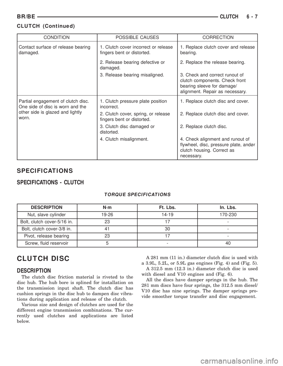
Nut, slave cylinder 19-26 14-19 170-230
Bolt, clutch cover-5/16 in. 23 17 -
Bolt, clutch cover-3/8 in. 41 30 -
Pivot, release bearing 23 17 -
Screw, fluid reservoir 5 - 40
CLUTCH DISC
DESCRIPTION
The clutch disc friction material is riveted to the
disc hub. The hub bore is splined for installation on
the transmission input shaft. The clutch disc has
cushion springs in the disc hub to dampen disc vibra-
tions during application and release of the clutch.
Various size and design of clutches are used for the
different engine transmission combinations. The cur-
rently used clutches and applications are listed
below.A 281 mm (11 in.) diameter clutch disc is used with
a 3.9L, 5.2L, or 5.9L gas engines (Fig. 4) and (Fig. 5).
A 312.5 mm (12.3 in.) diameter clutch disc is used
with diesel and V10 engines and (Fig. 6).
All the discs have damper springs in the hub. The
281 mm discs have four springs, the 312.5 mm diesel/
V10 disc has nine springs. The damper springs pro-
vide smoother torque transfer and disc engagement.
BR/BECLUTCH 6 - 7
CLUTCH (Continued)
Page 321 of 2889
OPERATION
The clutch disc is held onto the surface of the fly-
wheel by the force exerted by the pressure plate's
diaphragm spring. The friction material of the clutch
disc then transfers the engine torque from the fly-
wheel and pressure plate to the input shaft of the
transmission.
REMOVAL
(1) Raise and support vehicle.
(2) Support engine with wood block and adjustable
jack stand (Fig. 7). Supporting engine is necessary to
avoid undue strain on engine mounts.
(3) Remove transmission and transfer case, if
equipped. Refer to Group 21, Transmission and
Transfer Case, for proper procedures.
(4) If clutch cover will be reused, mark position of
cover on flywheel with paint or scriber (Fig. 8).
(5) Insert clutch alignment tool in clutch disc and
into pilot bushing. Tool will hold disc in place when
cover bolts are removed.
(6) If clutch cover will be reused, loosen cover bolts
evenly, only few threads at a time, and in a diagonal
pattern (Fig. 9). This relieves cover spring tension
evenly to avoid warping.
(7) Remove cover bolts completely and remove
cover, disc and alignment tool.
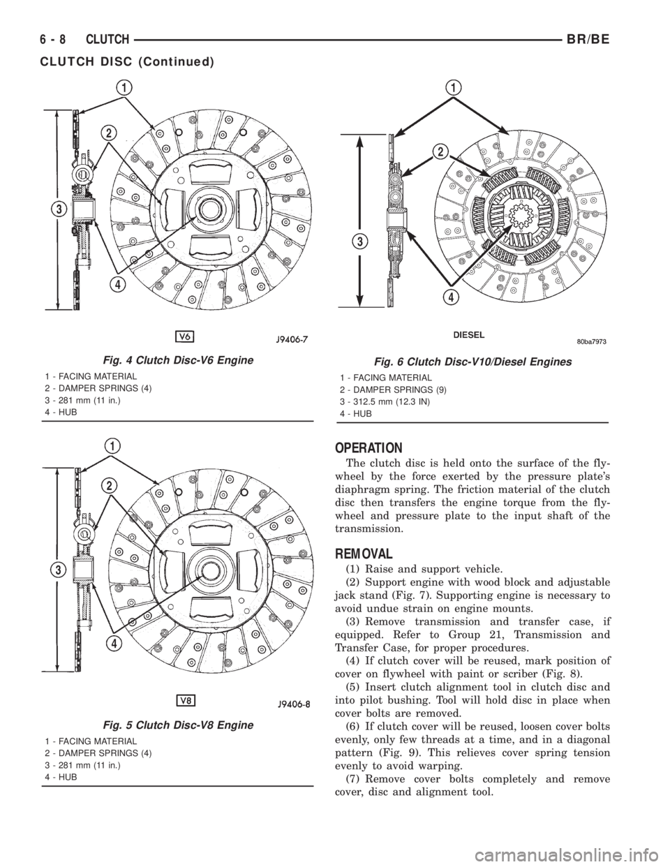
Fig. 4 Clutch Disc-V6 Engine
1 - FACING MATERIAL
2 - DAMPER SPRINGS (4)
3 - 281 mm (11 in.)
4 - HUB
Fig. 5 Clutch Disc-V8 Engine
1 - FACING MATERIAL
2 - DAMPER SPRINGS (4)
3 - 281 mm (11 in.)
4 - HUB
Fig. 6 Clutch Disc-V10/Diesel Engines
1 - FACING MATERIAL
2 - DAMPER SPRINGS (9)
3 - 312.5 mm (12.3 IN)
4 - HUB
6 - 8 CLUTCHBR/BE
CLUTCH DISC (Continued)