2001 DODGE RAM wheel bolt torque
[x] Cancel search: wheel bolt torquePage 1268 of 2889
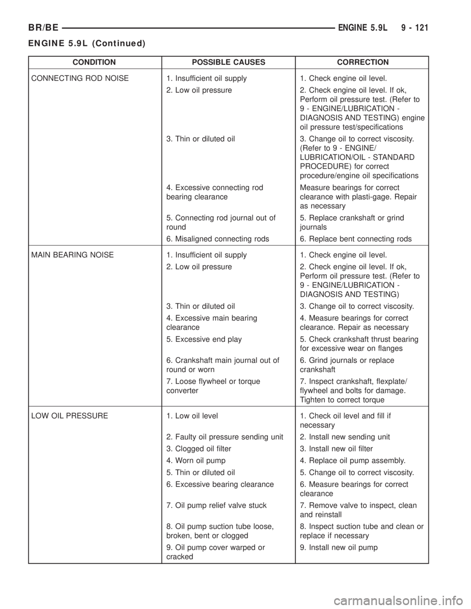
CONDITION POSSIBLE CAUSES CORRECTION
CONNECTING ROD NOISE 1. Insufficient oil supply 1. Check engine oil level.
2. Low oil pressure 2. Check engine oil level. If ok,
Perform oil pressure test. (Refer to
9 - ENGINE/LUBRICATION -
DIAGNOSIS AND TESTING) engine
oil pressure test/specifications
3. Thin or diluted oil 3. Change oil to correct viscosity.
(Refer to 9 - ENGINE/
LUBRICATION/OIL - STANDARD
PROCEDURE) for correct
procedure/engine oil specifications
4. Excessive connecting rod
bearing clearanceMeasure bearings for correct
clearance with plasti-gage. Repair
as necessary
5. Connecting rod journal out of
round5. Replace crankshaft or grind
journals
6. Misaligned connecting rods 6. Replace bent connecting rods
MAIN BEARING NOISE 1. Insufficient oil supply 1. Check engine oil level.
2. Low oil pressure 2. Check engine oil level. If ok,
Perform oil pressure test. (Refer to
9 - ENGINE/LUBRICATION -
DIAGNOSIS AND TESTING)
3. Thin or diluted oil 3. Change oil to correct viscosity.
4. Excessive main bearing
clearance4. Measure bearings for correct
clearance. Repair as necessary
5. Excessive end play 5. Check crankshaft thrust bearing
for excessive wear on flanges
6. Crankshaft main journal out of
round or worn6. Grind journals or replace
crankshaft
7. Loose flywheel or torque
converter7. Inspect crankshaft, flexplate/
flywheel and bolts for damage.
Tighten to correct torque
LOW OIL PRESSURE 1. Low oil level 1. Check oil level and fill if
necessary
2. Faulty oil pressure sending unit 2. Install new sending unit
3. Clogged oil filter 3. Install new oil filter
4. Worn oil pump 4. Replace oil pump assembly.
5. Thin or diluted oil 5. Change oil to correct viscosity.
6. Excessive bearing clearance 6. Measure bearings for correct
clearance
7. Oil pump relief valve stuck 7. Remove valve to inspect, clean
and reinstall
8. Oil pump suction tube loose,
broken, bent or clogged8. Inspect suction tube and clean or
replace if necessary
9. Oil pump cover warped or
cracked9. Install new oil pump
BR/BEENGINE 5.9L 9 - 121
ENGINE 5.9L (Continued)
Page 1280 of 2889
TORQUE
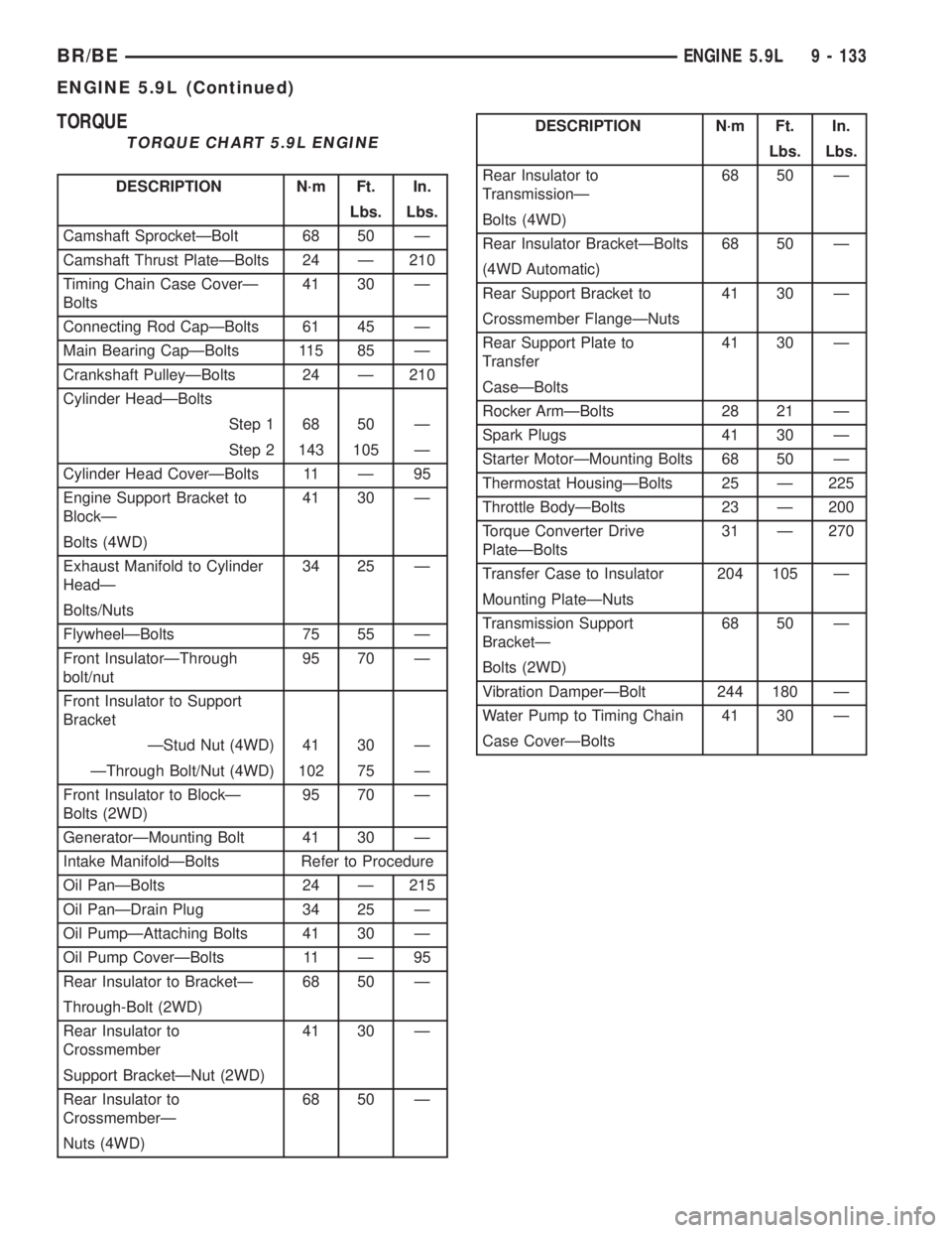
TORQUE CHART 5.9L ENGINE
DESCRIPTION N´m Ft. In.
Lbs. Lbs.
Camshaft SprocketÐBolt 68 50 Ð
Camshaft Thrust PlateÐBolts 24 Ð 210
Timing Chain Case CoverÐ
Bolts41 30 Ð
Connecting Rod CapÐBolts 61 45 Ð
Main Bearing CapÐBolts 115 85 Ð
Crankshaft PulleyÐBolts 24 Ð 210
Cylinder HeadÐBolts
Step 1 68 50 Ð
Step 2 143 105 Ð
Cylinder Head CoverÐBolts 11 Ð 95
Engine Support Bracket to
BlockÐ41 30 Ð
Bolts (4WD)
Exhaust Manifold to Cylinder
HeadÐ34 25 Ð
Bolts/Nuts
FlywheelÐBolts 75 55 Ð
Front InsulatorÐThrough
bolt/nut95 70 Ð
Front Insulator to Support
Bracket
ÐStud Nut (4WD) 41 30 Ð
ÐThrough Bolt/Nut (4WD) 102 75 Ð
Front Insulator to BlockÐ
Bolts (2WD)95 70 Ð
GeneratorÐMounting Bolt 41 30 Ð
Intake ManifoldÐBolts Refer to Procedure
Oil PanÐBolts 24 Ð 215
Oil PanÐDrain Plug 34 25 Ð
Oil PumpÐAttaching Bolts 41 30 Ð
Oil Pump CoverÐBolts 11 Ð 95
Rear Insulator to BracketÐ 68 50 Ð
Through-Bolt (2WD)
Rear Insulator to
Crossmember41 30 Ð
Support BracketÐNut (2WD)
Rear Insulator to
CrossmemberÐ68 50 Ð
Nuts (4WD)
DESCRIPTION N´m Ft. In.
Lbs. Lbs.
Rear Insulator to
TransmissionÐ68 50 Ð
Bolts (4WD)
Rear Insulator BracketÐBolts 68 50 Ð
(4WD Automatic)
Rear Support Bracket to 41 30 Ð
Crossmember FlangeÐNuts
Rear Support Plate to
Transfer41 30 Ð
CaseÐBolts
Rocker ArmÐBolts 28 21 Ð
Spark Plugs 41 30 Ð
Starter MotorÐMounting Bolts 68 50 Ð
Thermostat HousingÐBolts 25 Ð 225
Throttle BodyÐBolts 23 Ð 200
Torque Converter Drive
PlateÐBolts31 Ð 270
Transfer Case to Insulator 204 105 Ð
Mounting PlateÐNuts
Transmission Support
BracketÐ68 50 Ð
Bolts (2WD)
Vibration DamperÐBolt 244 180 Ð
Water Pump to Timing Chain 41 30 Ð
Case CoverÐBolts
BR/BEENGINE 5.9L 9 - 133
ENGINE 5.9L (Continued)
Page 1323 of 2889
CONDITION POSSIBLE CAUSES CORRECTION
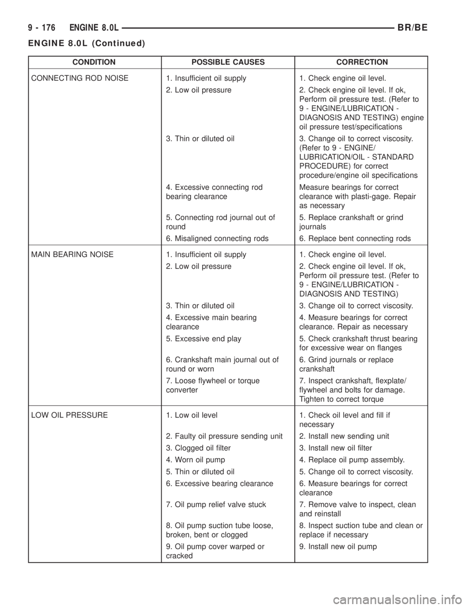
CONNECTING ROD NOISE 1. Insufficient oil supply 1. Check engine oil level.
2. Low oil pressure 2. Check engine oil level. If ok,
Perform oil pressure test. (Refer to
9 - ENGINE/LUBRICATION -
DIAGNOSIS AND TESTING) engine
oil pressure test/specifications
3. Thin or diluted oil 3. Change oil to correct viscosity.
(Refer to 9 - ENGINE/
LUBRICATION/OIL - STANDARD
PROCEDURE) for correct
procedure/engine oil specifications
4. Excessive connecting rod
bearing clearanceMeasure bearings for correct
clearance with plasti-gage. Repair
as necessary
5. Connecting rod journal out of
round5. Replace crankshaft or grind
journals
6. Misaligned connecting rods 6. Replace bent connecting rods
MAIN BEARING NOISE 1. Insufficient oil supply 1. Check engine oil level.
2. Low oil pressure 2. Check engine oil level. If ok,
Perform oil pressure test. (Refer to
9 - ENGINE/LUBRICATION -
DIAGNOSIS AND TESTING)
3. Thin or diluted oil 3. Change oil to correct viscosity.
4. Excessive main bearing
clearance4. Measure bearings for correct
clearance. Repair as necessary
5. Excessive end play 5. Check crankshaft thrust bearing
for excessive wear on flanges
6. Crankshaft main journal out of
round or worn6. Grind journals or replace
crankshaft
7. Loose flywheel or torque
converter7. Inspect crankshaft, flexplate/
flywheel and bolts for damage.
Tighten to correct torque
LOW OIL PRESSURE 1. Low oil level 1. Check oil level and fill if
necessary
2. Faulty oil pressure sending unit 2. Install new sending unit
3. Clogged oil filter 3. Install new oil filter
4. Worn oil pump 4. Replace oil pump assembly.
5. Thin or diluted oil 5. Change oil to correct viscosity.
6. Excessive bearing clearance 6. Measure bearings for correct
clearance
7. Oil pump relief valve stuck 7. Remove valve to inspect, clean
and reinstall
8. Oil pump suction tube loose,
broken, bent or clogged8. Inspect suction tube and clean or
replace if necessary
9. Oil pump cover warped or
cracked9. Install new oil pump
9 - 176 ENGINE 8.0LBR/BE
ENGINE 8.0L (Continued)
Page 1425 of 2889
CRANKSHAFT OIL SEAL -
REAR
REMOVAL
(1) Disconnect the battery negative cables.
(2) Remove the transmission and transfer case (if
equipped).
(3) Remove the clutch cover and disc (if manual
transmission equipped) (Refer to 6 - CLUTCH/
CLUTCH DISC - REMOVAL).
(4) Remove the flywheel or converter drive plate.
(5) Drill holes 180É apart into the seal. Be careful
not to contact the drill against the crankshaft.
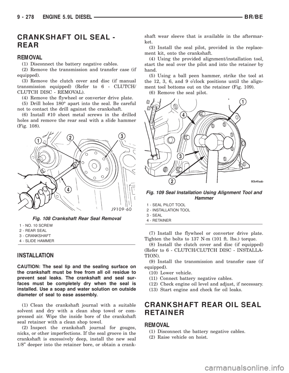
(6) Install #10 sheet metal screws in the drilled
holes and remove the rear seal with a slide hammer
(Fig. 108).
INSTALLATION
CAUTION: The seal lip and the sealing surface on
the crankshaft must be free from all oil residue to
prevent seal leaks. The crankshaft and seal sur-
faces must be completely dry when the seal is
installed. Use a soap and water solution on outside
diameter of seal to ease assembly.
(1) Clean the crankshaft journal with a suitable
solvent and dry with a clean shop towel or com-
pressed air. Wipe the inside bore of the crankshaft
seal retainer with a clean shop towel.
(2) Inspect the crankshaft journal for gouges,
nicks, or other imperfections. If the seal groove in the
crankshaft is excessively deep, install the new seal
1/8º deeper into the retainer bore, or obtain a crank-shaft wear sleeve that is available in the aftermar-
ket.
(3) Install the seal pilot, provided in the replace-
ment kit, onto the crankshaft.
(4) Using the provided alignment/installation tool,
start the seal over the pilot and into the retainer by
hand.
(5) Using a ball peen hammer, strike the tool at
the 12, 3, 6, and 9 o'clock positions until the align-
ment tool bottoms out on the retainer (Fig. 109).
(6) Remove the seal pilot.
(7) Install the flywheel or converter drive plate.
Tighten the bolts to 137 N´m (101 ft. lbs.) torque.
(8) Install the clutch cover and disc (if equipped)
(Refer to 6 - CLUTCH/CLUTCH DISC - INSTALLA-
TION).
(9) Install the transmission and transfer case (if
equipped).
(10) Lower vehicle.
(11) Connect battery negative cables.
(12) Check engine oil level and adjust, if necessary.
(13) Start engine and check for oil leaks.
CRANKSHAFT REAR OIL SEAL
RETAINER
REMOVAL
(1) Disconnect the battery negative cables.
(2) Raise vehicle on hoist.
Fig. 108 Crankshaft Rear Seal Removal
1 - NO. 10 SCREW
2 - REAR SEAL
3 - CRANKSHAFT
4 - SLIDE HAMMER
Fig. 109 Seal Installation Using Alignment Tool and
Hammer
1 - SEAL PILOT TOOL
2 - INSTALLATION TOOL
3 - SEAL
4 - RETAINER
9 - 278 ENGINE 5.9L DIESELBR/BE
Page 1426 of 2889
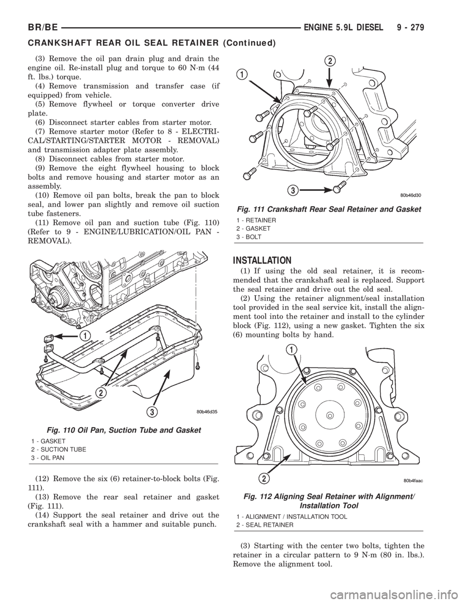
(3) Remove the oil pan drain plug and drain the
engine oil. Re-install plug and torque to 60 N´m (44
ft. lbs.) torque.
(4) Remove transmission and transfer case (if
equipped) from vehicle.
(5) Remove flywheel or torque converter drive
plate.
(6) Disconnect starter cables from starter motor.
(7) Remove starter motor (Refer to 8 - ELECTRI-
CAL/STARTING/STARTER MOTOR - REMOVAL)
and transmission adapter plate assembly.
(8) Disconnect cables from starter motor.
(9) Remove the eight flywheel housing to block
bolts and remove housing and starter motor as an
assembly.
(10) Remove oil pan bolts, break the pan to block
seal, and lower pan slightly and remove oil suction
tube fasteners.
(11) Remove oil pan and suction tube (Fig. 110)
(Refer to 9 - ENGINE/LUBRICATION/OIL PAN -
REMOVAL).
(12) Remove the six (6) retainer-to-block bolts (Fig.
111).
(13) Remove the rear seal retainer and gasket
(Fig. 111).
(14) Support the seal retainer and drive out the
crankshaft seal with a hammer and suitable punch.
INSTALLATION
(1) If using the old seal retainer, it is recom-
mended that the crankshaft seal is replaced. Support
the seal retainer and drive out the old seal.
(2) Using the retainer alignment/seal installation
tool provided in the seal service kit, install the align-
ment tool into the retainer and install to the cylinder
block (Fig. 112), using a new gasket. Tighten the six
(6) mounting bolts by hand.
(3) Starting with the center two bolts, tighten the
retainer in a circular pattern to 9 N´m (80 in. lbs.).
Remove the alignment tool.
Fig. 110 Oil Pan, Suction Tube and Gasket
1 - GASKET
2 - SUCTION TUBE
3 - OIL PAN
Fig. 111 Crankshaft Rear Seal Retainer and Gasket
1 - RETAINER
2 - GASKET
3 - BOLT
Fig. 112 Aligning Seal Retainer with Alignment/
Installation Tool
1 - ALIGNMENT / INSTALLATION TOOL
2 - SEAL RETAINER
BR/BEENGINE 5.9L DIESEL 9 - 279
CRANKSHAFT REAR OIL SEAL RETAINER (Continued)
Page 1427 of 2889
CAUTION: The seal lip and the sealing surface on
the crankshaft must be free from all oil residue to
prevent seal leaks. The crankshaft and seal sur-
faces must be completely dry when the seal is
installed. Use a soap and water solution on outside
diameter of seal to ease assembly.
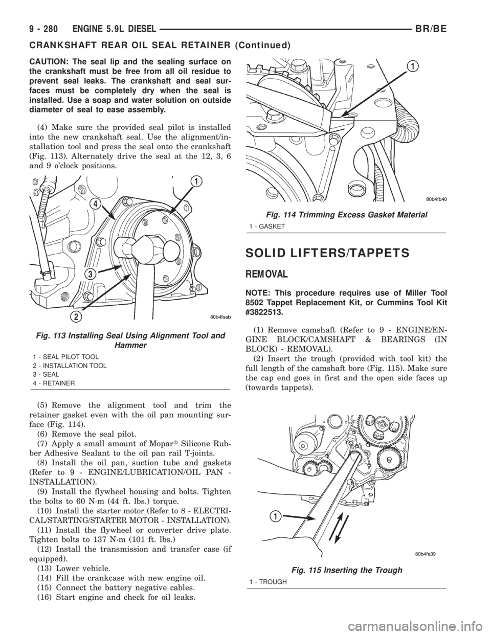
(4) Make sure the provided seal pilot is installed
into the new crankshaft seal. Use the alignment/in-
stallation tool and press the seal onto the crankshaft
(Fig. 113). Alternately drive the seal at the 12, 3, 6
and 9 o'clock positions.
(5) Remove the alignment tool and trim the
retainer gasket even with the oil pan mounting sur-
face (Fig. 114).
(6) Remove the seal pilot.
(7) Apply a small amount of MopartSilicone Rub-
ber Adhesive Sealant to the oil pan rail T-joints.
(8) Install the oil pan, suction tube and gaskets
(Refer to 9 - ENGINE/LUBRICATION/OIL PAN -
INSTALLATION).
(9) Install the flywheel housing and bolts. Tighten
the bolts to 60 N´m (44 ft. lbs.) torque.
(10)
Install the starter motor (Refer to 8 - ELECTRI-
CAL/STARTING/STARTER MOTOR - INSTALLATION).
(11) Install the flywheel or converter drive plate.
Tighten bolts to 137 N´m (101 ft. lbs.)
(12) Install the transmission and transfer case (if
equipped).
(13) Lower vehicle.
(14) Fill the crankcase with new engine oil.
(15) Connect the battery negative cables.
(16) Start engine and check for oil leaks.
SOLID LIFTERS/TAPPETS
REMOVAL
NOTE: This procedure requires use of Miller Tool
8502 Tappet Replacement Kit, or Cummins Tool Kit
#3822513.
(1) Remove camshaft (Refer to 9 - ENGINE/EN-
GINE BLOCK/CAMSHAFT & BEARINGS (IN
BLOCK) - REMOVAL).
(2) Insert the trough (provided with tool kit) the
full length of the camshaft bore (Fig. 115). Make sure
the cap end goes in first and the open side faces up
(towards tappets).
Fig. 115 Inserting the Trough
1 - TROUGH
Fig. 113 Installing Seal Using Alignment Tool and
Hammer
1 - SEAL PILOT TOOL
2 - INSTALLATION TOOL
3 - SEAL
4 - RETAINER
Fig. 114 Trimming Excess Gasket Material
1 - GASKET
9 - 280 ENGINE 5.9L DIESELBR/BE
CRANKSHAFT REAR OIL SEAL RETAINER (Continued)
Page 1443 of 2889
²Milky discoloration indicates coolant dilution.
(4) Clean the area around the oil filter head.
Remove the filter (Refer to 9 - ENGINE/LUBRICA-
TION/OIL FILTER - REMOVAL).
(5) Install new oil filter (Refer to 9 - ENGINE/LU-
BRICATION/OIL FILTER - INSTALLATION).
(6) Clean the drain plug and the sealing surface of
the pan. Check the condition of the threads and seal-
ing surface on the oil pan and drain plug.
(7) Install the drain plug. Tighten the plug to 60
N´m (44 ft. lbs.) torque.
(8) Use only High-Quality Multi-Viscosity lubricat-
ing oil in the Cummins Turbo Diesel engine. Choose
the correct oil for the operating conditions (Refer to
LUBRICATION & MAINTENANCE/FLUID TYPES -
DESCRIPTION).
(9) Fill the engine with the correct grade of new oil
(Refer to LUBRICATION & MAINTENANCE/FLUID
CAPACITIES - SPECIFICATIONS).
(10) Start the engine and operate it at idle for sev-
eral minutes. Check for leaks at the filter and drain
plug.
(11) Stop engine. Wait several minutes to allow the
oil to drain back to the pan and check the level
again.
USED ENGINE OIL DISPOSAL Care should be
exercised when disposing of used engine oil after
it has been drained from a vehicle's engine.
OIL COOLER & LINES
CLEANING AND INSPECTION
Clean the sealing surfaces.
Apply 483 kPa (70 psi) air pressure to the element
to check for leaks. If the element leaks, replace the
element.
OIL FILTER
REMOVAL
(1) Clean the area around the oil filter head.
Remove the filter using a 90-95 mm filter wrench.
(2) Clean the gasket surface of the filter head. The
filter canister O-Ring seal can stick on the filter
head. Make sure it is removed.
INSTALLATION
(1) Fill the oil filter element with clean oil before
installation. Use the same type oil that will be used
in the engine.
(2) Apply a light film of lubricating oil to the seal-
ing surface before installing the filter.CAUTION: Mechanical over-tightening may distort
the threads or damage the filter element seal.
(3) Install the filter until it contacts the sealing
surface of the oil filter adapter. Tighten filter an
additional ó turn.
OIL PAN
REMOVAL
(1) Disconnect the battery negative cables.
(2) Raise vehicle on hoist.
(3) Remove transmission and transfer case (if
equipped).
(4) Remove flywheel.
(5) Disconnect starter cables from starter motor.
(6) Remove starter motor (Refer to 8 - ELECTRI-
CAL/STARTING/STARTER MOTOR - REMOVAL)
and transmission adapter plate assembly.
WARNING: HOT OIL CAN CAUSE PERSONAL
INJURY.
(7) Drain the engine oil (Refer to 9 - ENGINE/LU-
BRICATION/OIL - STANDARD PROCEDURE).
(8) Install the oil pan drain plug with a new seal-
ing washer and tighten to 60 N´m (44 ft. lbs.) torque.
(9) Remove oil pan bolts, break the pan to block
seal, and lower pan slightly and remove oil suction
tube fasteners.
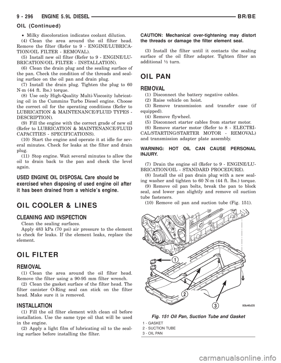
(10) Remove oil pan and suction tube (Fig. 151).
Fig. 151 Oil Pan, Suction Tube and Gasket
1 - GASKET
2 - SUCTION TUBE
3 - OIL PAN
9 - 296 ENGINE 5.9L DIESELBR/BE
OIL (Continued)
Page 1444 of 2889
CLEANING
Remove all gasket material from the oil pan and
cylinder block sealing surfaces. Extra effort may be
required around T-joint areas. Clean oil pan and
flush suction tube with a suitable solvent.
INSPECTION
Inspect the oil pan, suction tube, and tube braces
for cracks and damage. Replace any defective compo-
nent. Inspect the oil drain plug and drain hole
threads. Inspect the oil pan sealing surface for
straightness. Repair any minor imperfections with a
ball-peen hammer. Do not attempt to repair an oil
pan by welding.
INSTALLATION
(1) Fill the T-joint between the pan rail/gear hous-
ing and pan rail/rear seal retainer with sealant. Use
MopartSilicone Rubber Adhesive Sealant or equiva-
lent.
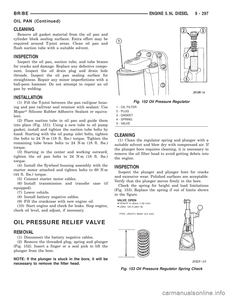
(2) Place suction tube in oil pan and guide them
into place (Fig. 151). Using a new tube to oil pump
gasket, install and tighten the suction tube bolts by
hand. Starting with the oil pump inlet bolts, tighten
the bolts to 24 N´m (18 ft. lbs.) torque. Tighten the
remaining tube brace bolts to 24 N´m (18 ft. lbs.)
torque.
(3) Starting in the center and working outward,
tighten the oil pan bolts to 24 N´m (18 ft. lbs.)
torque.
(4) Install the flywheel housing assembly with the
starter motor attached and tighten bolts to 60 N´m
(44 ft. lbs.) torque.
(5) Connect starter motor cables.
(6) Install transmission and transfer case (if
equipped).
(7) Lower vehicle.
(8) Install battery negative cables.
(9) Fill the crankcase with new engine oil.
(10) Start engine and check for leaks. Stop engine,
check oil level, and adjust, if necessary.
OIL PRESSURE RELIEF VALVE
REMOVAL
(1) Disconnect the battery negative cables.
(2) Remove the threaded plug, spring and plunger
(Fig. 152). Insert a finger or a seal pick to lift the
plunger from the bore.
NOTE: If the plunger is stuck in the bore, it will be
necessary to remove the filter head.
CLEANING
(1) Clean the regulator spring and plunger with a
suitable solvent and blow dry with compressed air. If
the plunger bore requires cleaning, it is necessary to
remove the oil filter head to avoid getting debris into
the engine.
INSPECTION
Inspect the plunger and plunger bore for cracks
and excessive wear. Polished surfaces are acceptable.
Verify that the plunger moves freely in the bore.
Check the spring for height and load limitations
(Fig. 153). Replace the spring if out of limits shown
in the figure.
Fig. 152 Oil Pressure Regulator
1 - OIL FILTER
2 - PLUG
3 - GASKET
4 - SPRING
5 - VALVE
Fig. 153 Oil Pressure Regulator Spring Check
BR/BEENGINE 5.9L DIESEL 9 - 297
OIL PAN (Continued)