2001 DODGE RAM wheel bolt torque
[x] Cancel search: wheel bolt torquePage 322 of 2889
INSTALLATION
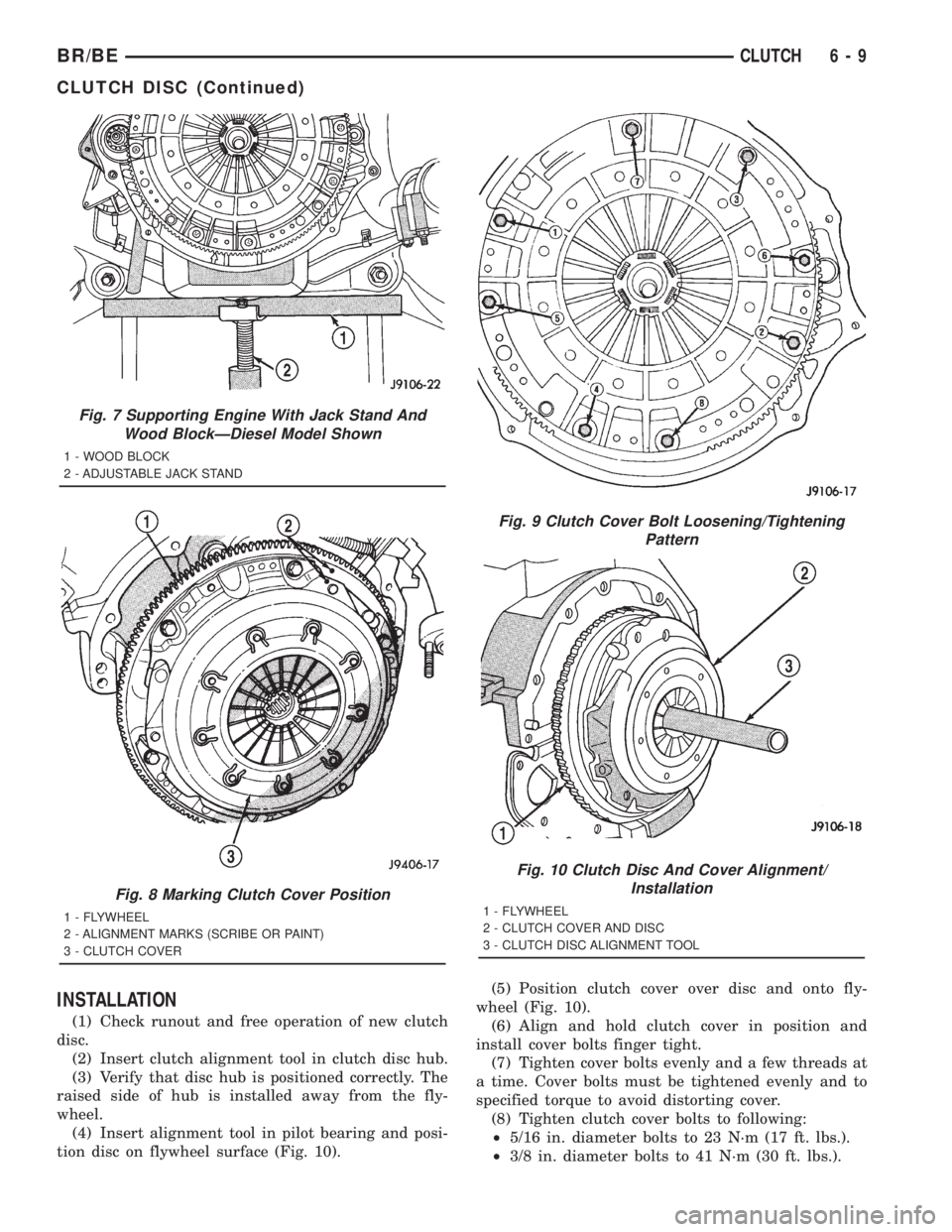
(1) Check runout and free operation of new clutch
disc.
(2) Insert clutch alignment tool in clutch disc hub.
(3) Verify that disc hub is positioned correctly. The
raised side of hub is installed away from the fly-
wheel.
(4) Insert alignment tool in pilot bearing and posi-
tion disc on flywheel surface (Fig. 10).(5) Position clutch cover over disc and onto fly-
wheel (Fig. 10).
(6) Align and hold clutch cover in position and
install cover bolts finger tight.
(7) Tighten cover bolts evenly and a few threads at
a time. Cover bolts must be tightened evenly and to
specified torque to avoid distorting cover.
(8) Tighten clutch cover bolts to following:
²5/16 in. diameter bolts to 23 N´m (17 ft. lbs.).
²3/8 in. diameter bolts to 41 N´m (30 ft. lbs.).
Fig. 7 Supporting Engine With Jack Stand And
Wood BlockÐDiesel Model Shown
1 - WOOD BLOCK
2 - ADJUSTABLE JACK STAND
Fig. 8 Marking Clutch Cover Position
1 - FLYWHEEL
2 - ALIGNMENT MARKS (SCRIBE OR PAINT)
3 - CLUTCH COVER
Fig. 9 Clutch Cover Bolt Loosening/Tightening
Pattern
Fig. 10 Clutch Disc And Cover Alignment/
Installation
1 - FLYWHEEL
2 - CLUTCH COVER AND DISC
3 - CLUTCH DISC ALIGNMENT TOOL
BR/BECLUTCH 6 - 9
CLUTCH DISC (Continued)
Page 327 of 2889
(4) Lubricate release fork and pivot contact sur-
faces with MopartHigh Temperature wheel bearing
grease before installation.
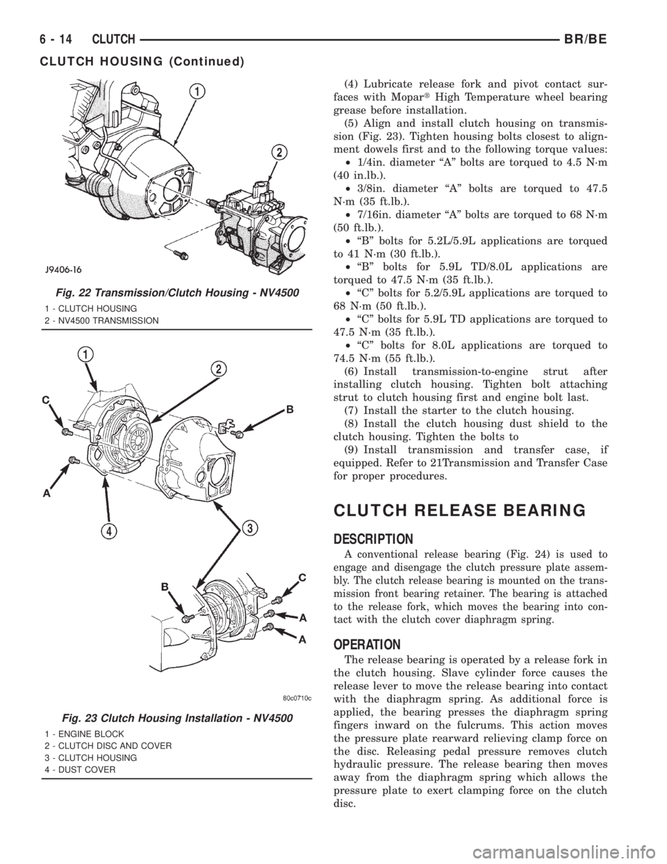
(5) Align and install clutch housing on transmis-
sion (Fig. 23). Tighten housing bolts closest to align-
ment dowels first and to the following torque values:
²1/4in. diameter ªAº bolts are torqued to 4.5 N´m
(40 in.lb.).
²3/8in. diameter ªAº bolts are torqued to 47.5
N´m (35 ft.lb.).
²7/16in. diameter ªAº bolts are torqued to 68 N´m
(50 ft.lb.).
²ªBº bolts for 5.2L/5.9L applications are torqued
to 41 N´m (30 ft.lb.).
²ªBº bolts for 5.9L TD/8.0L applications are
torqued to 47.5 N´m (35 ft.lb.).
²ªCº bolts for 5.2/5.9L applications are torqued to
68 N´m (50 ft.lb.).
²ªCº bolts for 5.9L TD applications are torqued to
47.5 N´m (35 ft.lb.).
²ªCº bolts for 8.0L applications are torqued to
74.5 N´m (55 ft.lb.).
(6) Install transmission-to-engine strut after
installing clutch housing. Tighten bolt attaching
strut to clutch housing first and engine bolt last.
(7) Install the starter to the clutch housing.
(8) Install the clutch housing dust shield to the
clutch housing. Tighten the bolts to
(9) Install transmission and transfer case, if
equipped. Refer to 21Transmission and Transfer Case
for proper procedures.
CLUTCH RELEASE BEARING
DESCRIPTION
A conventional release bearing (Fig. 24) is used to
engage and disengage the clutch pressure plate assem-
bly. The clutch release bearing is mounted on the trans-
mission front bearing retainer. The bearing is attached
to the release fork, which moves the bearing into con-
tact with the clutch cover diaphragm spring.
OPERATION
The release bearing is operated by a release fork in
the clutch housing. Slave cylinder force causes the
release lever to move the release bearing into contact
with the diaphragm spring. As additional force is
applied, the bearing presses the diaphragm spring
fingers inward on the fulcrums. This action moves
the pressure plate rearward relieving clamp force on
the disc. Releasing pedal pressure removes clutch
hydraulic pressure. The release bearing then moves
away from the diaphragm spring which allows the
pressure plate to exert clamping force on the clutch
disc.
Fig. 22 Transmission/Clutch Housing - NV4500
1 - CLUTCH HOUSING
2 - NV4500 TRANSMISSION
Fig. 23 Clutch Housing Installation - NV4500
1 - ENGINE BLOCK
2 - CLUTCH DISC AND COVER
3 - CLUTCH HOUSING
4 - DUST COVER
6 - 14 CLUTCHBR/BE
CLUTCH HOUSING (Continued)
Page 330 of 2889
shaft speeds and releasing the energy back into the
system when the crankshaft slows down.
DIAGNOSIS AND TESTING - FLYWHEEL
Check flywheel runout whenever misalignment is
suspected. Flywheel runout should not exceed 0.08
mm (0.003 in.). Measure runout at the outer edge of
the flywheel face with a dial indicator. Mount the
indicator on a stud installed in place of one of the fly-
wheel bolts.
Common causes of runout are:
²heat warpage
²improper machining
²incorrect bolt tightening
²improper seating on crankshaft flange shoulder
²foreign material on crankshaft flange
Flywheel machining is not recommended. The fly-
wheel clutch surface is machined to a unique contour
and machining will negate this feature. However,
minor flywheel scoring can be cleaned up by hand with
180 grit emery, or with surface grinding equipment.
Remove only enough material to reduce scoring
(approximately 0.001 - 0.003 in.). Heavy stock removal
isnot recommended.
Replace the flywheel if scoring
is severe and deeper than 0.076 mm (0.003 in.).
Excessive stock removal can result in flywheel crack-
ing or warpage after installation; it can also weaken
the flywheel and interfere with proper clutch release.
Clean the crankshaft flange before mounting the
flywheel. Dirt and grease on the flange surface may
cock the flywheel causing excessive runout. Use new
bolts when remounting a flywheel and secure the
bolts with MopartLock And Seal. Tighten flywheel
bolts to specified torque only. Overtightening can dis-
tort the flywheel hub causing runout.
DISASSEMBLY
NOTE: If the teeth are worn or damaged, the fly-
wheel should be replaced as an assembly. This is
the recommended and preferred method of repair.
In cases where a new flywheel is not readily avail-
able, (V10/Diesel Engine only) a replacement ring
gear can be installed. The following procedure must
be observed to avoid damaging the flywheel and
replacement gear.
WARNING: WEAR PROTECTIVE GOGGLES OR
SAFETY GLASSES WHILE CUTTING RING GEAR.
(1) Mark position of the old gear for alignment ref-
erence on the flywheel. Use a scriber for this pur-
pose.
(2) Remove the old gear by cutting most of the way
through it (at one point) with an abrasive cut-off
wheel. Then complete removal with a cold chisel or
punch.
ASSEMBLY
NOTE: The ring gear is a shrink fit on the flywheel.
This means the gear must be expanded by heating
in order to install it. The method of heating and
expanding the gear is extremely important. Every
surface of the gear must be heated at the same
time to produce uniform expansion. An oven or
similar enclosed heating device must be used. Tem-
perature required for uniform expansion is approxi-
mately 375É F.
CAUTION: Do not use an oxy/acetylene torch to
remove the old gear, or to heat and expand a new
gear. The high temperature of the torch flame can
cause localized heating that will damage the fly-
wheel. In addition, using the torch to heat a replace-
ment gear will cause uneven heating and
expansion. The torch flame can also anneal the
gear teeth resulting in rapid wear and damage after
installation.
WARNING: WEAR PROTECTIVE GOGGLES OR
SAFETY GLASSES AND HEAT RESISTENT GLOVES
WHEN HANDLING A HEATED RING GEAR.
(1) The heated gear must be installed evenly to
avoid misalignment or distortion.
(2) Position and install the heated ring gear on the
flywheel with a shop press and a suitable press
plates.
(3) Place flywheel on work bench and let it cool in
normal shop air. Allow the ring gear to cool down
completely before installation it on the engine.
CAUTION: Do not use water or compressed air to
cool the flywheel. The rapid cooling produced by
water or compressed air will distort or crack the
new gear.
PILOT BEARING
DESCRIPTION
Vehicles equipped with a manual transmission uti-
lize a pilot bearing. This bearing is located in the
back of the engine crankshaft. Depending on the type
of engine or application, the pilot bearing can be a
solid soft metallic bushing or a fully caged needle
bearing. The pilot bearing's main functions are to
support the transmission input shaft, maintain
proper alignment of the clutch assembly and allow
the transmission main shaft to rotate at a different
speed than the engine mounted crankshaft.
BR/BECLUTCH 6 - 17
FLYWHEEL (Continued)
Page 1154 of 2889
CONDITION POSSIBLE CAUSES CORRECTION
4. Excessive main bearing clearance 4. Measure bearings for correct
clearance. Repair as necessary
5. Excessive end play 5. Check crankshaft thrust bearing for
excessive wear on flanges
6. Crankshaft main journal out of
round or worn6. Grind journals or replace crankshaft
7. Loose flywheel or torque converter 7. Inspect crankshaft, flexplate/flywheel
and bolts for damage. Tighten to correct
torque
LOW OIL PRESSURE 1. Low oil level 1. Check oil level and fill if necessary
2. Faulty oil pressure sending unit 2. Install new sending unit
3. Clogged oil filter 3. Install new oil filter
4. Worn oil pump 4. Replace oil pump assembly.
5. Thin or diluted oil 5. Change oil to correct viscosity.
6. Excessive bearing clearance 6. Measure bearings for correct clearance
7. Oil pump relief valve stuck 7. Remove valve to inspect, clean and
reinstall
8. Oil pump suction tube loose,
broken, bent or clogged8. Inspect suction tube and clean or
replace if necessary
9. Oil pump cover warped or cracked 9. Install new oil pump
OIL LEAKS 1. Misaligned or deteriorated gaskets 1. Replace gasket
2. Loose fastener, broken or porous
metal part2. Tighten, repair or replace the part
3. Front or rear crankshaft oil seal
leaking3. Replace seal
4. Leaking oil gallery plug or cup plug 4. Remove and reseal threaded plug.
Replace cup style plug
EXCESSIVE OIL
CONSUMPTION OR
SPARK PLUGS OIL
FOULED1. CCV System malfunction 1. (Refer to 25 - EMISSIONS CONTROL/
EVAPORATIVE EMISSIONS -
DESCRIPTION) for correct operation
2. Defective valve stem seal(s) 2. Repair or replace seal(s)
3. Worn or broken piston rings 3. Hone cylinder bores. Install new rings
4. Scuffed pistons/cylinder walls 4. Hone cylinder bores and replace
pistons as required
5. Carbon in oil control ring groove 5. Remove rings and de-carbon piston
6. Worn valve guides 6. Inspect/replace valve guides as
necessary
7. Piston rings fitted too tightly in
grooves7. Remove rings and check ring end gap
and side clearance. Replace if necessary
BR/BEENGINE 3.9L 9 - 7
ENGINE 3.9L (Continued)
Page 1165 of 2889
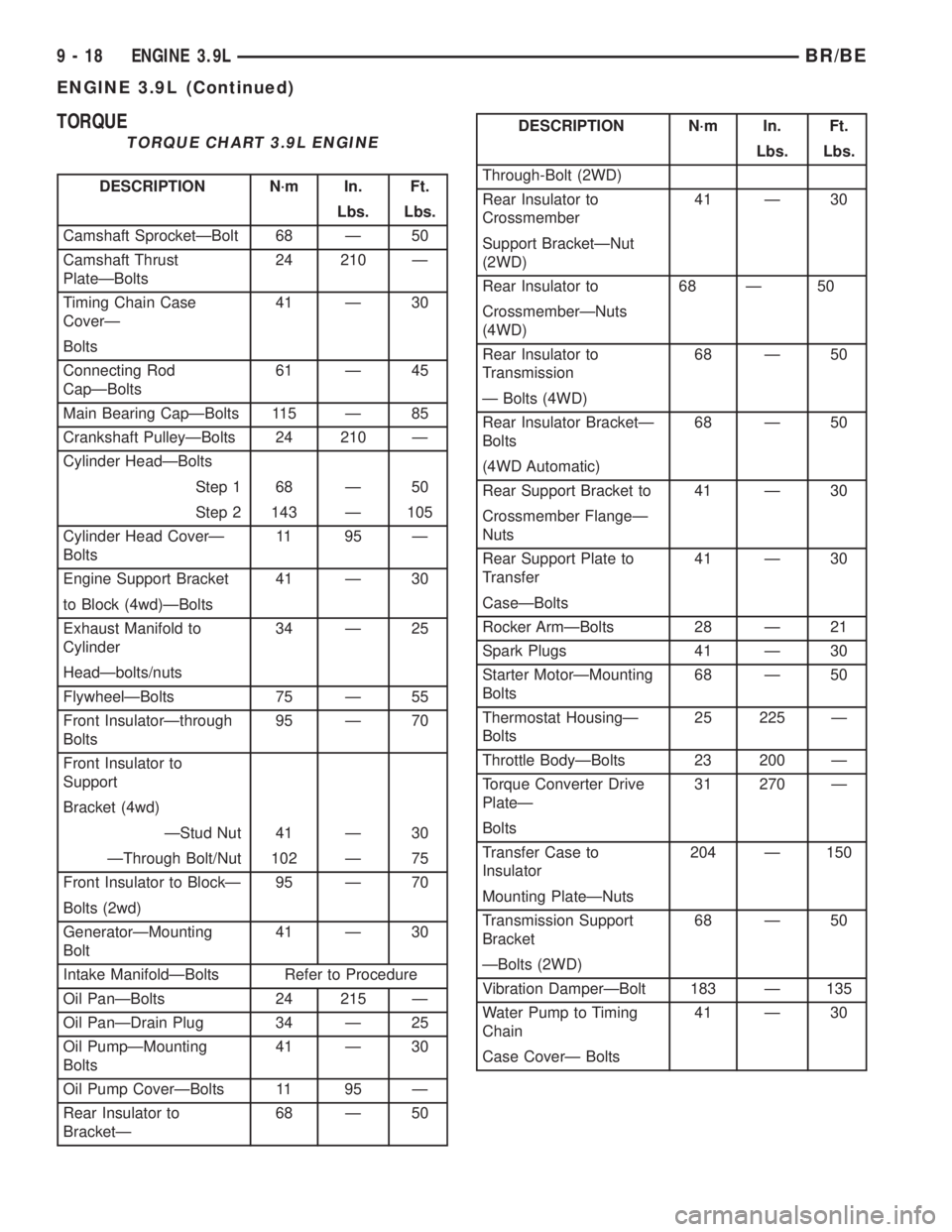
TORQUE
TORQUE CHART 3.9L ENGINE
DESCRIPTION N´m In. Ft.
Lbs. Lbs.
Camshaft SprocketÐBolt 68 Ð 50
Camshaft Thrust
PlateÐBolts24 210 Ð
Timing Chain Case
CoverÐ41 Ð 30
Bolts
Connecting Rod
CapÐBolts61 Ð 45
Main Bearing CapÐBolts 115 Ð 85
Crankshaft PulleyÐBolts 24 210 Ð
Cylinder HeadÐBolts
Step 1 68 Ð 50
Step 2 143 Ð 105
Cylinder Head CoverÐ
Bolts11 95 Ð
Engine Support Bracket 41 Ð 30
to Block (4wd)ÐBolts
Exhaust Manifold to
Cylinder34 Ð 25
HeadÐbolts/nuts
FlywheelÐBolts 75 Ð 55
Front InsulatorÐthrough
Bolts95 Ð 70
Front Insulator to
Support
Bracket (4wd)
ÐStud Nut 41 Ð 30
ÐThrough Bolt/Nut 102 Ð 75
Front Insulator to BlockÐ 95 Ð 70
Bolts (2wd)
GeneratorÐMounting
Bolt41 Ð 30
Intake ManifoldÐBolts Refer to Procedure
Oil PanÐBolts 24 215 Ð
Oil PanÐDrain Plug 34 Ð 25
Oil PumpÐMounting
Bolts41 Ð 30
Oil Pump CoverÐBolts 11 95 Ð
Rear Insulator to
BracketÐ68 Ð 50
DESCRIPTION N´m In. Ft.
Lbs. Lbs.
Through-Bolt (2WD)
Rear Insulator to
Crossmember41 Ð 30
Support BracketÐNut
(2WD)
Rear Insulator to 68 Ð 50
CrossmemberÐNuts
(4WD)
Rear Insulator to
Transmission68 Ð 50
Ð Bolts (4WD)
Rear Insulator BracketÐ
Bolts68 Ð 50
(4WD Automatic)
Rear Support Bracket to 41 Ð 30
Crossmember FlangeÐ
Nuts
Rear Support Plate to
Transfer41 Ð 30
CaseÐBolts
Rocker ArmÐBolts 28 Ð 21
Spark Plugs 41 Ð 30
Starter MotorÐMounting
Bolts68 Ð 50
Thermostat HousingÐ
Bolts25 225 Ð
Throttle BodyÐBolts 23 200 Ð
Torque Converter Drive
PlateÐ31 270 Ð
Bolts
Transfer Case to
Insulator204 Ð 150
Mounting PlateÐNuts
Transmission Support
Bracket68 Ð 50
ÐBolts (2WD)
Vibration DamperÐBolt 183 Ð 135
Water Pump to Timing
Chain41 Ð 30
Case CoverÐ Bolts
9 - 18 ENGINE 3.9LBR/BE
ENGINE 3.9L (Continued)
Page 1178 of 2889
(8) Turn crankshaft and camshaft to line up with
keyway location in crankshaft sprocket and in cam-
shaft sprocket.
(9) Lift sprockets and chain (keep sprockets tight
against the chain in position as described).
(10) Slide both sprockets evenly over their respec-
tive shafts and use a straightedge to check alignment
of timing marks (Fig. 22).
(11) Install the camshaft bolt/cup washer. Tighten
bolt to 68 N´m (50 ft. lbs.) torque.
(12) Measure camshaft end play (Fig. 23). (Refer to
9 - ENGINE - SPECIFICATIONS) for proper clear-
ance. If not within limits, install a new timing chain
tensioner.
(13) Each tappet reused must be installed in the
same position at which it was removed.When cam-
shaft is replaced, all of the tappets must be
replaced.Install hydraulic tappets (Refer to 9 -
ENGINE/ENGINE BLOCK/HYDRAULIC LIFTERS
(CAM IN BLOCK) - INSTALLATION).
(14) Install timing chain cover (Refer to 9 -
ENGINE/VALVE TIMING/TIMING BELT / CHAIN
COVER(S) - INSTALLATION).
(15) Install intake manifold (Refer to 9 - ENGINE/
MANIFOLDS/INTAKE MANIFOLD - INSTALLA-
TION).
(16) Install distributor.
(17) Install cylinder head covers (Refer to 9 -
ENGINE/CYLINDER HEAD/CYLINDER HEAD
COVER(S) - INSTALLATION).
(18) Install radiator (Refer to 7 - COOLING/EN-
GINE/RADIATOR - INSTALLATION).
(19) Fill cooling system (Refer to 7 - COOLING -
STANDARD PROCEDURE).
(20) Connect battery negative cable.
(21) Start engine and check for leaks.
CONNECTING ROD BEARINGS
STANDARD PROCEDURE-CONNECTING ROD
BEARING FITTING
Fit all rods on a bank until completed. DO NOT
alternate from one bank to another, because connect-
ing rods and pistons are not interchangeable from
one bank to another.
The bearing caps are not interchangeable and
should be marked at removal to ensure correct
assembly.
Each bearing cap has a small V-groove across the
parting face. When installing the lower bearing shell,
be certain that the V-groove in the shell is in line
with the V-groove in the cap. This provides lubrica-
tion of the cylinder wall in the opposite bank.The bearing shells must be installed so that the
tangs are in the machined grooves in the rods and
caps.
Limits of taper or out-of-round on any crankshaft
journals should be held to 0.025 mm (0.001 in.).
Bearings are available in 0.025 mm (0.001 in.), 0.051
mm (0.002 in.), 0.076 mm (0.003 in.), 0.254 mm
(0.010 in.) and 0.305 mm (0.012 in.) undersize.
Install the bearings in pairs. DO NOT use a new
bearing half with an old bearing half. DO NOT
file the rods or bearing caps.
CRANKSHAFT
DESCRIPTION
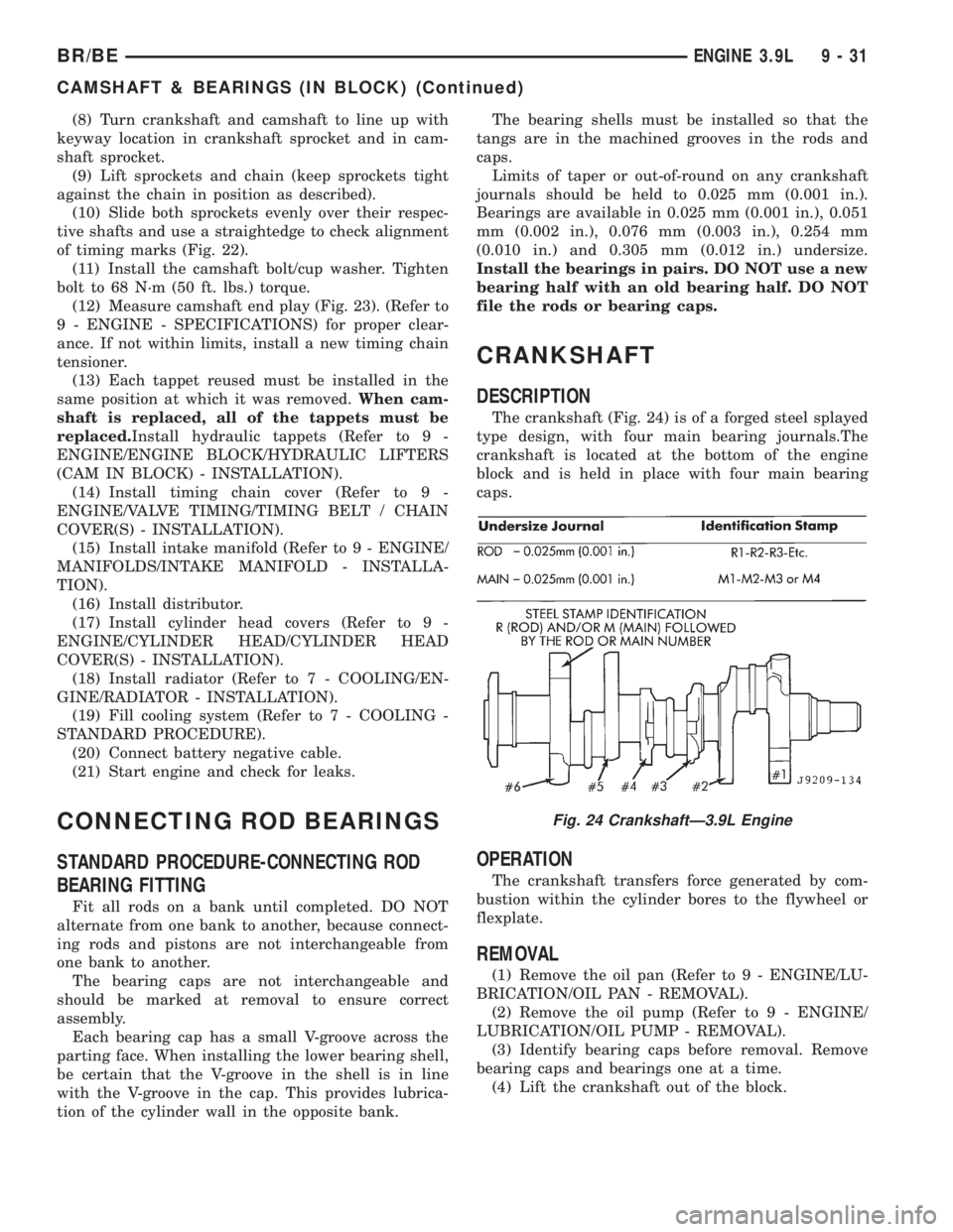
The crankshaft (Fig. 24) is of a forged steel splayed
type design, with four main bearing journals.The
crankshaft is located at the bottom of the engine
block and is held in place with four main bearing
caps.
OPERATION
The crankshaft transfers force generated by com-
bustion within the cylinder bores to the flywheel or
flexplate.
REMOVAL
(1) Remove the oil pan (Refer to 9 - ENGINE/LU-
BRICATION/OIL PAN - REMOVAL).
(2) Remove the oil pump (Refer to 9 - ENGINE/
LUBRICATION/OIL PUMP - REMOVAL).
(3) Identify bearing caps before removal. Remove
bearing caps and bearings one at a time.
(4) Lift the crankshaft out of the block.
Fig. 24 CrankshaftÐ3.9L Engine
BR/BEENGINE 3.9L 9 - 31
CAMSHAFT & BEARINGS (IN BLOCK) (Continued)
Page 1211 of 2889
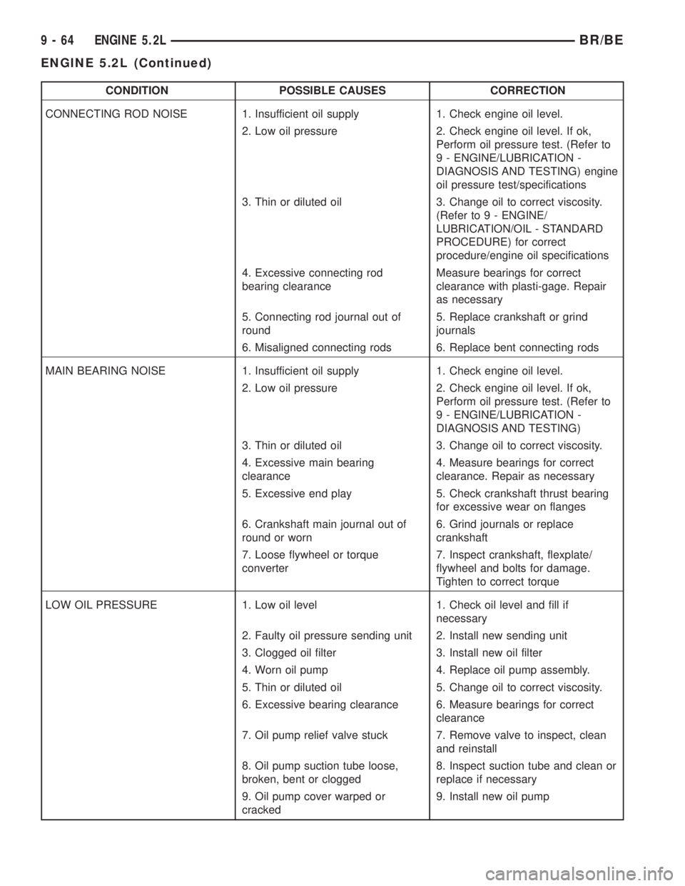
CONDITION POSSIBLE CAUSES CORRECTION
CONNECTING ROD NOISE 1. Insufficient oil supply 1. Check engine oil level.
2. Low oil pressure 2. Check engine oil level. If ok,
Perform oil pressure test. (Refer to
9 - ENGINE/LUBRICATION -
DIAGNOSIS AND TESTING) engine
oil pressure test/specifications
3. Thin or diluted oil 3. Change oil to correct viscosity.
(Refer to 9 - ENGINE/
LUBRICATION/OIL - STANDARD
PROCEDURE) for correct
procedure/engine oil specifications
4. Excessive connecting rod
bearing clearanceMeasure bearings for correct
clearance with plasti-gage. Repair
as necessary
5. Connecting rod journal out of
round5. Replace crankshaft or grind
journals
6. Misaligned connecting rods 6. Replace bent connecting rods
MAIN BEARING NOISE 1. Insufficient oil supply 1. Check engine oil level.
2. Low oil pressure 2. Check engine oil level. If ok,
Perform oil pressure test. (Refer to
9 - ENGINE/LUBRICATION -
DIAGNOSIS AND TESTING)
3. Thin or diluted oil 3. Change oil to correct viscosity.
4. Excessive main bearing
clearance4. Measure bearings for correct
clearance. Repair as necessary
5. Excessive end play 5. Check crankshaft thrust bearing
for excessive wear on flanges
6. Crankshaft main journal out of
round or worn6. Grind journals or replace
crankshaft
7. Loose flywheel or torque
converter7. Inspect crankshaft, flexplate/
flywheel and bolts for damage.
Tighten to correct torque
LOW OIL PRESSURE 1. Low oil level 1. Check oil level and fill if
necessary
2. Faulty oil pressure sending unit 2. Install new sending unit
3. Clogged oil filter 3. Install new oil filter
4. Worn oil pump 4. Replace oil pump assembly.
5. Thin or diluted oil 5. Change oil to correct viscosity.
6. Excessive bearing clearance 6. Measure bearings for correct
clearance
7. Oil pump relief valve stuck 7. Remove valve to inspect, clean
and reinstall
8. Oil pump suction tube loose,
broken, bent or clogged8. Inspect suction tube and clean or
replace if necessary
9. Oil pump cover warped or
cracked9. Install new oil pump
9 - 64 ENGINE 5.2LBR/BE
ENGINE 5.2L (Continued)
Page 1223 of 2889
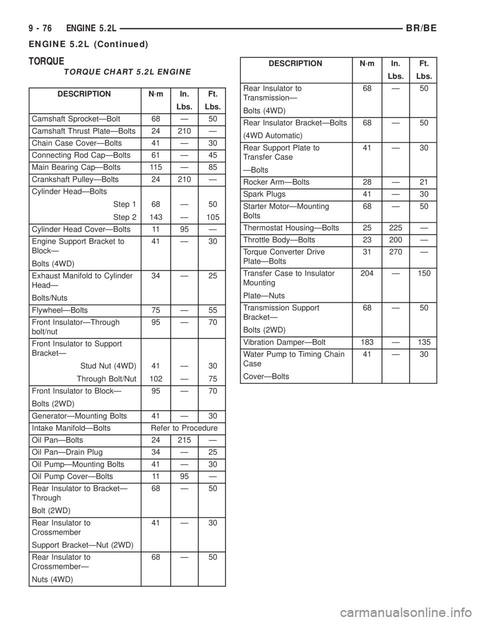
TORQUE
TORQUE CHART 5.2L ENGINE
DESCRIPTION N´m In. Ft.
Lbs. Lbs.
Camshaft SprocketÐBolt 68 Ð 50
Camshaft Thrust PlateÐBolts 24 210 Ð
Chain Case CoverÐBolts 41 Ð 30
Connecting Rod CapÐBolts 61 Ð 45
Main Bearing CapÐBolts 115 Ð 85
Crankshaft PulleyÐBolts 24 210 Ð
Cylinder HeadÐBolts
Step 1 68 Ð 50
Step 2 143 Ð 105
Cylinder Head CoverÐBolts 11 95 Ð
Engine Support Bracket to
BlockÐ41 Ð 30
Bolts (4WD)
Exhaust Manifold to Cylinder
HeadÐ34 Ð 25
Bolts/Nuts
FlywheelÐBolts 75 Ð 55
Front InsulatorÐThrough
bolt/nut95 Ð 70
Front Insulator to Support
BracketÐ
Stud Nut (4WD) 41 Ð 30
Through Bolt/Nut 102 Ð 75
Front Insulator to BlockÐ 95 Ð 70
Bolts (2WD)
GeneratorÐMounting Bolts 41 Ð 30
Intake ManifoldÐBolts Refer to Procedure
Oil PanÐBolts 24 215 Ð
Oil PanÐDrain Plug 34 Ð 25
Oil PumpÐMounting Bolts 41 Ð 30
Oil Pump CoverÐBolts 11 95 Ð
Rear Insulator to BracketÐ
Through68 Ð 50
Bolt (2WD)
Rear Insulator to
Crossmember41 Ð 30
Support BracketÐNut (2WD)
Rear Insulator to
CrossmemberÐ68 Ð 50
Nuts (4WD)
DESCRIPTION N´m In. Ft.
Lbs. Lbs.
Rear Insulator to
TransmissionÐ68 Ð 50
Bolts (4WD)
Rear Insulator BracketÐBolts 68 Ð 50
(4WD Automatic)
Rear Support Plate to
Transfer Case41 Ð 30
ÐBolts
Rocker ArmÐBolts 28 Ð 21
Spark Plugs 41 Ð 30
Starter MotorÐMounting
Bolts68 Ð 50
Thermostat HousingÐBolts 25 225 Ð
Throttle BodyÐBolts 23 200 Ð
Torque Converter Drive
PlateÐBolts31 270 Ð
Transfer Case to Insulator
Mounting204 Ð 150
PlateÐNuts
Transmission Support
BracketÐ68 Ð 50
Bolts (2WD)
Vibration DamperÐBolt 183 Ð 135
Water Pump to Timing Chain
Case41 Ð 30
CoverÐBolts
9 - 76 ENGINE 5.2LBR/BE
ENGINE 5.2L (Continued)