2001 DODGE RAM maintenance
[x] Cancel search: maintenancePage 478 of 2889
lead dioxide (positive plate) or sponge lead (negative
plate). Insulators or plate separators made of a non-
conductive material are inserted between the positive
and negative plates to prevent them from contacting
or shorting against one another. These dissimilar
metal plates are submerged in a sulfuric acid and
water solution called an electrolyte.
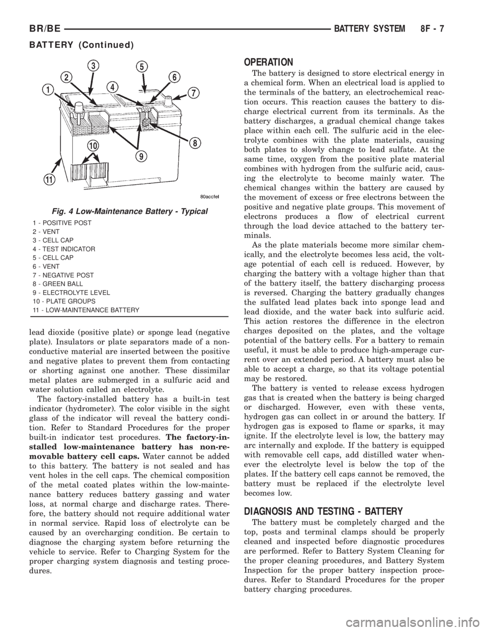
The factory-installed battery has a built-in test
indicator (hydrometer). The color visible in the sight
glass of the indicator will reveal the battery condi-
tion. Refer to Standard Procedures for the proper
built-in indicator test procedures.The factory-in-
stalled low-maintenance battery has non-re-
movable battery cell caps.Water cannot be added
to this battery. The battery is not sealed and has
vent holes in the cell caps. The chemical composition
of the metal coated plates within the low-mainte-
nance battery reduces battery gassing and water
loss, at normal charge and discharge rates. There-
fore, the battery should not require additional water
in normal service. Rapid loss of electrolyte can be
caused by an overcharging condition. Be certain to
diagnose the charging system before returning the
vehicle to service. Refer to Charging System for the
proper charging system diagnosis and testing proce-
dures.
OPERATION
The battery is designed to store electrical energy in
a chemical form. When an electrical load is applied to
the terminals of the battery, an electrochemical reac-
tion occurs. This reaction causes the battery to dis-
charge electrical current from its terminals. As the
battery discharges, a gradual chemical change takes
place within each cell. The sulfuric acid in the elec-
trolyte combines with the plate materials, causing
both plates to slowly change to lead sulfate. At the
same time, oxygen from the positive plate material
combines with hydrogen from the sulfuric acid, caus-
ing the electrolyte to become mainly water. The
chemical changes within the battery are caused by
the movement of excess or free electrons between the
positive and negative plate groups. This movement of
electrons produces a flow of electrical current
through the load device attached to the battery ter-
minals.
As the plate materials become more similar chem-
ically, and the electrolyte becomes less acid, the volt-
age potential of each cell is reduced. However, by
charging the battery with a voltage higher than that
of the battery itself, the battery discharging process
is reversed. Charging the battery gradually changes
the sulfated lead plates back into sponge lead and
lead dioxide, and the water back into sulfuric acid.
This action restores the difference in the electron
charges deposited on the plates, and the voltage
potential of the battery cells. For a battery to remain
useful, it must be able to produce high-amperage cur-
rent over an extended period. A battery must also be
able to accept a charge, so that its voltage potential
may be restored.
The battery is vented to release excess hydrogen
gas that is created when the battery is being charged
or discharged. However, even with these vents,
hydrogen gas can collect in or around the battery. If
hydrogen gas is exposed to flame or sparks, it may
ignite. If the electrolyte level is low, the battery may
arc internally and explode. If the battery is equipped
with removable cell caps, add distilled water when-
ever the electrolyte level is below the top of the
plates. If the battery cell caps cannot be removed, the
battery must be replaced if the electrolyte level
becomes low.
DIAGNOSIS AND TESTING - BATTERY
The battery must be completely charged and the
top, posts and terminal clamps should be properly
cleaned and inspected before diagnostic procedures
are performed. Refer to Battery System Cleaning for
the proper cleaning procedures, and Battery System
Inspection for the proper battery inspection proce-
dures. Refer to Standard Procedures for the proper
battery charging procedures.
Fig. 4 Low-Maintenance Battery - Typical
1 - POSITIVE POST
2 - VENT
3 - CELL CAP
4 - TEST INDICATOR
5 - CELL CAP
6 - VENT
7 - NEGATIVE POST
8 - GREEN BALL
9 - ELECTROLYTE LEVEL
10 - PLATE GROUPS
11 - LOW-MAINTENANCE BATTERY
BR/BEBATTERY SYSTEM 8F - 7
BATTERY (Continued)
Page 483 of 2889
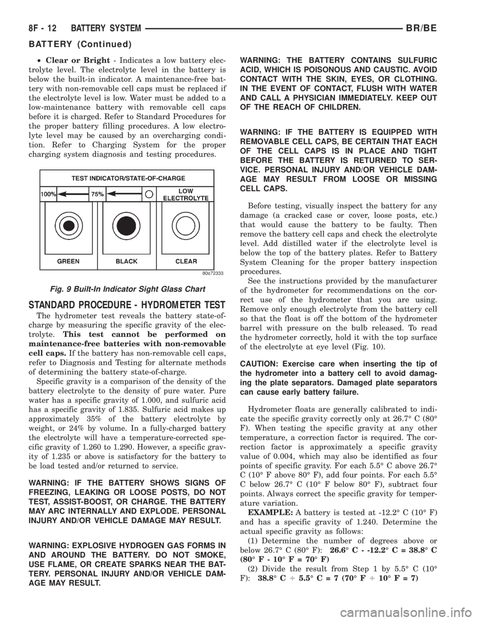
²Clear or Bright- Indicates a low battery elec-
trolyte level. The electrolyte level in the battery is
below the built-in indicator. A maintenance-free bat-
tery with non-removable cell caps must be replaced if
the electrolyte level is low. Water must be added to a
low-maintenance battery with removable cell caps
before it is charged. Refer to Standard Procedures for
the proper battery filling procedures. A low electro-
lyte level may be caused by an overcharging condi-
tion. Refer to Charging System for the proper
charging system diagnosis and testing procedures.
STANDARD PROCEDURE - HYDROMETER TEST
The hydrometer test reveals the battery state-of-
charge by measuring the specific gravity of the elec-
trolyte.This test cannot be performed on
maintenance-free batteries with non-removable
cell caps.If the battery has non-removable cell caps,
refer to Diagnosis and Testing for alternate methods
of determining the battery state-of-charge.
Specific gravity is a comparison of the density of the
battery electrolyte to the density of pure water. Pure
water has a specific gravity of 1.000, and sulfuric acid
has a specific gravity of 1.835. Sulfuric acid makes up
approximately 35% of the battery electrolyte by
weight, or 24% by volume. In a fully-charged battery
the electrolyte will have a temperature-corrected spe-
cific gravity of 1.260 to 1.290. However, a specific grav-
ity of 1.235 or above is satisfactory for the battery to
be load tested and/or returned to service.
WARNING: IF THE BATTERY SHOWS SIGNS OF
FREEZING, LEAKING OR LOOSE POSTS, DO NOT
TEST, ASSIST-BOOST, OR CHARGE. THE BATTERY
MAY ARC INTERNALLY AND EXPLODE. PERSONAL
INJURY AND/OR VEHICLE DAMAGE MAY RESULT.
WARNING: EXPLOSIVE HYDROGEN GAS FORMS IN
AND AROUND THE BATTERY. DO NOT SMOKE,
USE FLAME, OR CREATE SPARKS NEAR THE BAT-
TERY. PERSONAL INJURY AND/OR VEHICLE DAM-
AGE MAY RESULT.WARNING: THE BATTERY CONTAINS SULFURIC
ACID, WHICH IS POISONOUS AND CAUSTIC. AVOID
CONTACT WITH THE SKIN, EYES, OR CLOTHING.
IN THE EVENT OF CONTACT, FLUSH WITH WATER
AND CALL A PHYSICIAN IMMEDIATELY. KEEP OUT
OF THE REACH OF CHILDREN.
WARNING: IF THE BATTERY IS EQUIPPED WITH
REMOVABLE CELL CAPS, BE CERTAIN THAT EACH
OF THE CELL CAPS IS IN PLACE AND TIGHT
BEFORE THE BATTERY IS RETURNED TO SER-
VICE. PERSONAL INJURY AND/OR VEHICLE DAM-
AGE MAY RESULT FROM LOOSE OR MISSING
CELL CAPS.
Before testing, visually inspect the battery for any
damage (a cracked case or cover, loose posts, etc.)
that would cause the battery to be faulty. Then
remove the battery cell caps and check the electrolyte
level. Add distilled water if the electrolyte level is
below the top of the battery plates. Refer to Battery
System Cleaning for the proper battery inspection
procedures.
See the instructions provided by the manufacturer
of the hydrometer for recommendations on the cor-
rect use of the hydrometer that you are using.
Remove only enough electrolyte from the battery cell
so that the float is off the bottom of the hydrometer
barrel with pressure on the bulb released. To read
the hydrometer correctly, hold it with the top surface
of the electrolyte at eye level (Fig. 10).
CAUTION: Exercise care when inserting the tip of
the hydrometer into a battery cell to avoid damag-
ing the plate separators. Damaged plate separators
can cause early battery failure.
Hydrometer floats are generally calibrated to indi-
cate the specific gravity correctly only at 26.7É C (80É
F). When testing the specific gravity at any other
temperature, a correction factor is required. The cor-
rection factor is approximately a specific gravity
value of 0.004, which may also be identified as four
points of specific gravity. For each 5.5É C above 26.7É
C (10É F above 80É F), add four points. For each 5.5É
C below 26.7É C (10É F below 80É F), subtract four
points. Always correct the specific gravity for temper-
ature variation.
EXAMPLE:A battery is tested at -12.2É C (10É F)
and has a specific gravity of 1.240. Determine the
actual specific gravity as follows:
(1) Determine the number of degrees above or
below 26.7É C (80É F):26.6É C - -12.2É C = 38.8É C
(80É F - 10É F = 70É F)
(2) Divide the result from Step 1 by 5.5É C (10É
F):38.8É C45.5ÉC=7(70É F410ÉF=7)
Fig. 9 Built-In Indicator Sight Glass Chart
8F - 12 BATTERY SYSTEMBR/BE
BATTERY (Continued)
Page 553 of 2889
SPARK PLUG
DESCRIPTION
The 3.9L V-6 and 5.2L/5.9L V-8 engines use resis-
tor type spark plugs. The 8.0L V-10 engine uses
inductive type spark plugs.
Spark plug resistance values range from 6,000 to
20,000 ohms (when checked with at least a 1000 volt
spark plug tester).Do not use an ohmmeter to
check the resistance values of the spark plugs.
Inaccurate readings will result.
OPERATION
To prevent possible pre-ignition and/or mechanical
engine damage, the correct type/heat range/number
spark plug must be used.
Always use the recommended torque when tighten-
ing spark plugs. Incorrect torque can distort the
spark plug and change plug gap. It can also pull the
plug threads and do possible damage to both the
spark plug and the cylinder head.
Remove the spark plugs and examine them for
burned electrodes and fouled, cracked or broken por-
celain insulators. Keep plugs arranged in the order
in which they were removed from the engine. A sin-gle plug displaying an abnormal condition indicates
that a problem exists in the corresponding cylinder.
Replace spark plugs at the intervals recommended in
Group O, Lubrication and Maintenance
Spark plugs that have low mileage may be cleaned
and reused if not otherwise defective, carbon or oil
fouled. Also refer to Spark Plug Conditions.
CAUTION: Never use a motorized wire wheel brush
to clean the spark plugs. Metallic deposits will
remain on the spark plug insulator and will cause
plug misfire.
DIAGNOSIS AND TESTING - SPARK PLUG
CONDITIONS
NORMAL OPERATING
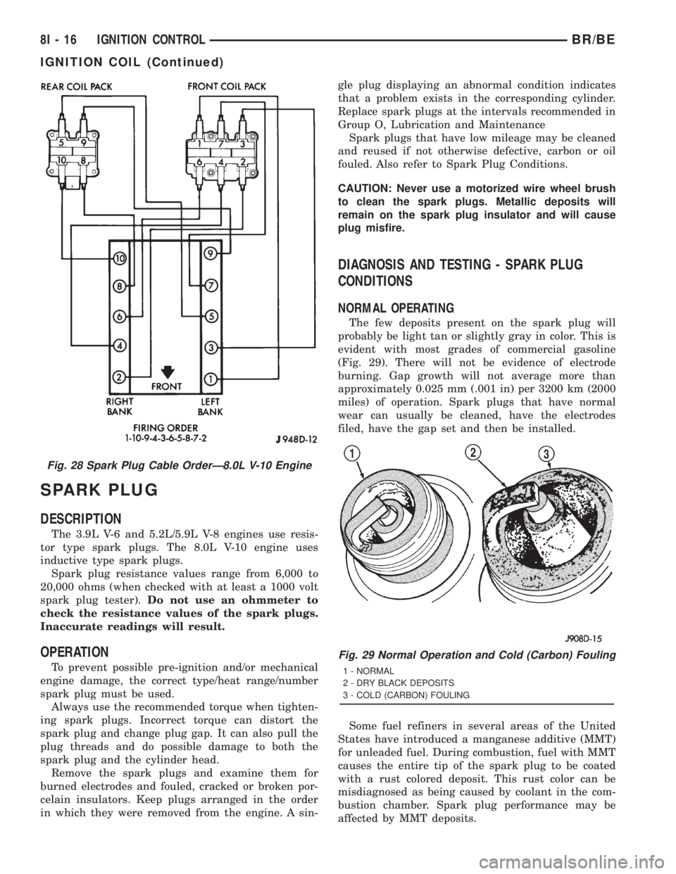
The few deposits present on the spark plug will
probably be light tan or slightly gray in color. This is
evident with most grades of commercial gasoline
(Fig. 29). There will not be evidence of electrode
burning. Gap growth will not average more than
approximately 0.025 mm (.001 in) per 3200 km (2000
miles) of operation. Spark plugs that have normal
wear can usually be cleaned, have the electrodes
filed, have the gap set and then be installed.
Some fuel refiners in several areas of the United
States have introduced a manganese additive (MMT)
for unleaded fuel. During combustion, fuel with MMT
causes the entire tip of the spark plug to be coated
with a rust colored deposit. This rust color can be
misdiagnosed as being caused by coolant in the com-
bustion chamber. Spark plug performance may be
affected by MMT deposits.
Fig. 28 Spark Plug Cable OrderÐ8.0L V-10 Engine
Fig. 29 Normal Operation and Cold (Carbon) Fouling
1 - NORMAL
2 - DRY BLACK DEPOSITS
3 - COLD (CARBON) FOULING
8I - 16 IGNITION CONTROLBR/BE
IGNITION COIL (Continued)
Page 587 of 2889

turn on the seatbelt indicator for the following rea-
sons:
²Seatbelt Reminder Function- Each time the
cluster receives a battery current input on the fused
ignition switch output (st-run) circuit, the indicator
will be illuminated as a seatbelt reminder for about
seven seconds, or until the ignition switch is turned
to the Off position, whichever occurs first. This
reminder function will occur regardless of the status
of the seatbelt switch input to the cluster.
²Driver Side Front Seatbelt Not Buckled-
Following the seatbelt reminder function, each time
the cluster receives a ground input on the seat belt
switch sense circuit (seatbelt switch closed - seatbelt
unbuckled) with the ignition switch in the Start or
On positions, the indicator will be illuminated. The
seatbelt indicator remains illuminated until the seat
belt switch sense input to the cluster is an open cir-
cuit (seatbelt switch opened - seatbelt buckled), or
until the ignition switch is turned to the Off position,
whichever occurs first.
²Actuator Test- Each time the cluster is put
through the actuator test, the indicator will be
turned on during the bulb check portion of the test to
confirm the functionality of the LED and the cluster
control circuitry.
The seatbelt switch input to the instrument cluster
circuitry can be diagnosed using conventional diag-
nostic tools and methods. For further diagnosis of the
seatbelt indicator or the instrument cluster circuitry
that controls the LED, (Refer to 8 - ELECTRICAL/
INSTRUMENT CLUSTER - DIAGNOSIS AND
TESTING).
SERVICE REMINDER
INDICATOR
DESCRIPTION
A Service Reminder Indicator (SRI) is standard
equipment on all instrument clusters. However, on
vehicles not equipped with certain optional heavy
duty emission cycle gasoline engines, this indicator is
electronically disabled. The SRI is located near the
lower edge of the instrument cluster overlay, to the
left of center. The SRI consists of a stencilled cutout
of the words ªMAINT REQDº in the opaque layer of
the instrument cluster overlay. The dark outer layer
of the overlay prevents the indicator from being
clearly visible when it is not illuminated. An amber
lens behind the cutout in the opaque layer of the
overlay causes the ªMAINT REQDº text to appear in
amber through the translucent outer layer of the
overlay when the indicator is illuminated from
behind by a Light Emitting Diode (LED) soldered
onto the instrument cluster electronic circuit board.The SRI is serviced as a unit with the instrument
cluster.
OPERATION
The Service Reminder Indicator (SRI) gives an
indication to the vehicle operator when engine emis-
sions maintenance procedures should be performed.
This indicator is controlled by a transistor on the
instrument cluster circuit board based upon the clus-
ter programming and electronic messages received by
the cluster from the Powertrain Control Module
(PCM) over the Chrysler Collision Detection (CCD)
data bus. The SRI Light Emitting Diode (LED)
receives battery current on the instrument cluster
electronic circuit board through the fused ignition
switch output (st-run) circuit whenever the ignition
switch is in the On or Start positions; therefore, the
LED will always be off when the ignition switch is in
any position except On or Start. The LED only illu-
minates when it is provided a path to ground by the
instrument cluster transistor. The instrument cluster
will turn on the SRI for the following reasons:
²Bulb Test- Each time the ignition switch is
turned to the On position the SRI is illuminated for
about two seconds as a bulb test.
²Service Required Lamp-On Message- Each
time the cluster receives a service required lamp-on
message from the PCM indicating that an emissions
maintenance interval has been reached, the SRI will
be illuminated. The indicator remains illuminated
until the cluster receives a service required lamp-off
message from the PCM, or until the ignition switch
is turned to the Off position, whichever occurs first.
²Actuator Test- Each time the cluster is put
through the actuator test, the SRI will be turned on
during the bulb check portion of the test to confirm
the functionality of the LED and the cluster control
circuitry.
The PCM continually monitors the vehicle speed
sensor to determine the distance the vehicle has been
driven, then sends the proper messages to the instru-
ment cluster. Once the SRI has been illuminated and
the required emissions maintenance procedures have
been completed, the PCM must be reset using a
DRBIIItscan tool before it will send the proper ser-
vice required lamp-off message to the instrument
cluster. Refer to the appropriate diagnostic informa-
tion. For further diagnosis of the SRI or the instru-
ment cluster circuitry that controls the LED, (Refer
to 8 - ELECTRICAL/INSTRUMENT CLUSTER -
DIAGNOSIS AND TESTING). For proper diagnosis
of the PCM, the CCD data bus, or the message
inputs to the instrument cluster that control the SRI,
a DRBIIItscan tool is required. Refer to the appro-
priate diagnostic information.
8J - 28 INSTRUMENT CLUSTERBR/BE
SEATBELT INDICATOR (Continued)
Page 630 of 2889
LAMPS/LIGHTING - INTERIOR
TABLE OF CONTENTS
page page
LAMPS/LIGHTING - INTERIOR
SPECIFICATIONS........................33
DOME LAMP
REMOVAL..............................33
INSTALLATION...........................33
DOOR AJAR SWITCH
DESCRIPTION...........................34
DIAGNOSIS AND TESTING.................34
DOOR AJAR SWITCH....................34
REMOVAL..............................35
INSTALLATION...........................35GLOVE BOX LAMP AND SWITCH
REMOVAL..............................35
INSTALLATION...........................35
READING LAMP
DESCRIPTION...........................36
OPERATION.............................36
REMOVAL..............................36
INSTALLATION...........................36
VANITY LAMP
REMOVAL..............................37
INSTALLATION...........................37
LAMPS/LIGHTING - INTERIOR
SPECIFICATIONS
INTERIOR LAMPS
LAMP BULB
A/C HEATER CONTROL 158
ASH RECEIVER 161
CIGAR LIGHTER 161
HEADLAMP SWITCH 158
HEATER CONTROL 158
INSTRUMENT CLUSTER PC194
RADIO ASC
AIRBAG HIGH LINE PC194
AIRBAG LOW LINE PC74
ANTI-LOCK BRAKE PC74
BATTERY VOLTAGE PC194
BRAKE WARNING PC194
CHECK ENGINE PC74
ENGINE OIL PRESSURE PC74
FOUR WHEEL DRIVE PC194
HIGH BEAM PC194
LOW FUEL PC194
LOW WASHER FLUID PC74
MAINTENANCE
REQUIREDPC74
MESSAGE CENTER PC194
SEAT BELT PC74
LAMP BULB
TURN SIGNAL PC194
UPSHIFT PC74
DOME 1004
GLOVE COMPARTMENT 1891
VANITY MIRROR LAMP P/N 6501966
DOME LAMP
REMOVAL
(1) Using a small flat blade, pry the left side (driv-
er's side) of the dome lamp lens downward from
dome lamp.
(2) Allow the lens to hang down (Fig. 1) , this will
disengage the right side of the lamp (passenger's
side) from the headliner.
(3) Pull the right side of the lamp down and slide
the lamp to the right (Fig. 2) .
(4) Separate the lamp from the headliner.
(5) Disengage dome lamp wire connector from body
wire harness.
(6) Separate dome lamp from vehicle.
INSTALLATION
(1) Position dome lamp at headliner.
(2) Connect dome lamp wire connector to body
wire harness.
(3) Position the left side of the lamp in the head-
liner opening and slide lamp to the left.
(4) Push the right side of the lamp in the head-
liner opening and push the lamp lens up into the
lamp to secure.
BR/BELAMPS/LIGHTING - INTERIOR 8L - 33
Page 1150 of 2889
ENGINE 3.9L
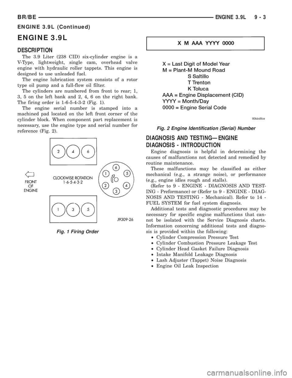
DESCRIPTION
The 3.9 Liter (238 CID) six-cylinder engine is a
V-Type, lightweight, single cam, overhead valve
engine with hydraulic roller tappets. This engine is
designed to use unleaded fuel.
The engine lubrication system consists of a rotor
type oil pump and a full-flow oil filter.
The cylinders are numbered from front to rear; 1,
3, 5 on the left bank and 2, 4, 6 on the right bank.
The firing order is 1-6-5-4-3-2 (Fig. 1).
The engine serial number is stamped into a
machined pad located on the left front corner of the
cylinder block. When component part replacement is
necessary, use the engine type and serial number for
reference (Fig. 2).
DIAGNOSIS AND TESTINGÐENGINE
DIAGNOSIS - INTRODUCTION
Engine diagnosis is helpful in determining the
causes of malfunctions not detected and remedied by
routine maintenance.
These malfunctions may be classified as either
mechanical (e.g., a strange noise), or performance
(e.g., engine idles rough and stalls).
(Refer to 9 - ENGINE - DIAGNOSIS AND TEST-
ING - Preformance) or (Refer to 9 - ENGINE - DIAG-
NOSIS AND TESTING - Mechanical). Refer to 14 -
FUEL SYSTEM for fuel system diagnosis.
Additional tests and diagnostic procedures may be
necessary for specific engine malfunctions that can-
not be isolated with the Service Diagnosis charts.
Information concerning additional tests and diagno-
sis is provided within the following:
²Cylinder Compression Pressure Test
²Cylinder Combustion Pressure Leakage Test
²Cylinder Head Gasket Failure Diagnosis
²Intake Manifold Leakage Diagnosis
²Lash Adjuster (Tappet) Noise Diagnosis
²Engine Oil Leak Inspection
Fig. 1 Firing Order
Fig. 2 Engine Identification (Serial) Number
BR/BEENGINE 3.9L 9 - 3
ENGINE 3.9L (Continued)
Page 1158 of 2889
(4) A controlled hone motor speed between 200 and
300 RPM is necessary to obtain the proper cross-
hatch angle. The number of up and down strokes per
minute can be regulated to get the desired 50É to 60É
angle. Faster up and down strokes increase the cross-
hatch angle.
(5) After honing, it is necessary that the block be
cleaned to remove all traces of abrasive. Use a brush
to wash parts with a solution of hot water and deter-
gent. Dry parts thoroughly. Use a clean, white, lint-
free cloth to check that the bore is clean. Oil the
bores after cleaning to prevent rusting.
STANDARD PROCEDUREÐHYDROSTATIC
LOCK
CAUTION: DO NOT use the starter motor to rotate
the crankshaft. Severe damage could occur.
When an engine is suspected of hydrostatic lock
(regardless of what caused the problem), follow the
steps below.
(1) Perform the Fuel Pressure Release Procedure
(Refer to 14 - FUEL SYSTEM/FUEL DELIVERY -
STANDARD PROCEDURE).
(2) Disconnect the negative cable(s) from the bat-
tery.
(3) Inspect air cleaner, induction system, and
intake manifold to ensure system is dry and clear of
foreign material.
(4) Place a shop towel around the spark plugs to
catch any fluid that may possibly be under pressure
in the cylinder head. Remove the spark plugs.
(5) With all spark plugs removed, rotate the crank-
shaft using a breaker bar and socket.
(6) Identify the fluid in the cylinders (coolant, fuel,
oil, etc.).
(7) Be sure all fluid has been removed from the
cylinders.
(8) Repair engine or components as necessary to
prevent this problem from occurring again.
(9) Squirt a small amount of engine oil into the
cylinders to lubricate the walls. This will prevent
damage on restart.
(10) Install new spark plugs. Tighten the spark
plugs to 41 N´m (30 ft. lbs.) torque.
(11) Drain engine oil. Remove and discard the oil
filter.
(12) Install the drain plug. Tighten the plug to 34
N´m (25 ft. lbs.) torque.
(13) Install a new oil filter.
(14) Fill engine crankcase with the specified
amount and grade of oil. (Refer to LUBRICATION &
MAINTENANCE - SPECIFICATIONS).
(15) Connect the negative cable(s) to the battery.
(16) Start the engine and check for any leaks.
STANDARD PROCEDUREÐREPAIR DAMAGED
OR WORN THREADS
CAUTION: Be sure that the tapped holes maintain
the original center line.
Damaged or worn threads can be repaired. Essen-
tially, this repair consists of:
²Drilling out worn or damaged threads.
²Tapping the hole with a special Heli-Coil Tap, or
equivalent.
²Installing an insert into the tapped hole to bring
the hole back to its original thread size.
STANDARD PROCEDUREÐFORM-IN-PLACE
GASKETS & SEALERS
There are numerous places where form-in-place
gaskets are used on the engine. Care must be taken
when applying form-in-place gaskets to assure
obtaining the desired results.Do not use form-in-
place gasket material unless specified.Bead size,
continuity, and location are of great importance. Too
thin a bead can result in leakage while too much can
result in spill-over which can break off and obstruct
fluid feed lines. A continuous bead of the proper
width is essential to obtain a leak-free gasket.
There are numerous types of form-in-place gasket
materials that are used in the engine area. Mopart
Engine RTV GEN II, MopartATF-RTV, and Mopart
Gasket Maker gasket materials, each have different
properties and can not be used in place of the other.
MOPARtENGINE RTV GEN II
MopartEngine RTV GEN II is used to seal com-
ponents exposed to engine oil. This material is a spe-
cially designed black silicone rubber RTV that
retains adhesion and sealing properties when
exposed to engine oil. Moisture in the air causes the
material to cure. This material is available in three
ounce tubes and has a shelf life of one year. After one
year this material will not properly cure. Always
inspect the package for the expiration date before
use.
MOPARtATF RTV
MopartATF RTV is a specifically designed black
silicone rubber RTV that retains adhesion and seal-
ing properties to seal components exposed to auto-
matic transmission fluid, engine coolants, and
moisture. This material is available in three ounce
tubes and has a shelf life of one year. After one year
this material will not properly cure. Always inspect
the package for the expiration date before use.
MOPARtGASKET MAKER
MopartGasket Maker is an anaerobic type gasket
material. The material cures in the absence of air
when squeezed between two metallic surfaces. It will
not cure if left in the uncovered tube. The anaerobic
BR/BEENGINE 3.9L 9 - 11
ENGINE 3.9L (Continued)
Page 1168 of 2889
AIR CLEANER ELEMENT
REMOVAL - 3.9L/5.2L/5.9L
For air cleaner element required maintenance
schedules (listed in time or mileage intervals), refer
to 0, Lubrication and Maintenance.
CAUTION: Do not attempt to remove air cleaner ele-
ment (filter) from housing by removing top cover
only. To prevent damage to air cleaner housing, the
entire air cleaner housing assembly must be
removed from engine for air cleaner element
replacement.
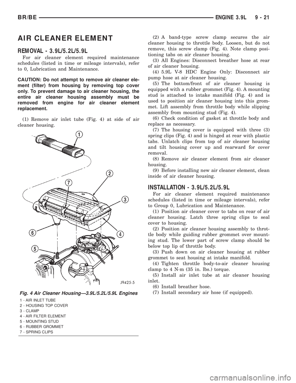
(1) Remove air inlet tube (Fig. 4) at side of air
cleaner housing.(2) A band-type screw clamp secures the air
cleaner housing to throttle body. Loosen, but do not
remove, this screw clamp (Fig. 4). Note clamp posi-
tioning tabs on air cleaner housing.
(3) All Engines: Disconnect breather hose at rear
of air cleaner housing.
(4) 5.9L V-8 HDC Engine Only: Disconnect air
pump hose at air cleaner housing.
(5) The bottom/front of air cleaner housing is
equipped with a rubber grommet (Fig. 4). A mounting
stud is attached to intake manifold (Fig. 4) and is
used to position air cleaner housing into this grom-
met. Lift assembly from throttle body while slipping
assembly from mounting stud (Fig. 4).
(6) Check condition of gasket at throttle body and
replace as necessary.
(7) The housing cover is equipped with three (3)
spring clips (Fig. 4) and is hinged at rear with plastic
tabs. Unlatch clips from top of air cleaner housing
and tilt housing cover up and rearward for cover
removal.
(8) Remove air cleaner element from air cleaner
housing.
(9) Before installing new air cleaner element, clean
inside of air cleaner housing.
INSTALLATION - 3.9L/5.2L/5.9L
For air cleaner element required maintenance
schedules (listed in time or mileage intervals), refer
to Group 0, Lubrication and Maintenance.
(1) Position air cleaner cover to tabs on rear of air
cleaner housing. Latch three spring clips to seal
cover to housing.
(2) Position air cleaner housing assembly to throt-
tle body while guiding rubber grommet over mount-
ing stud. The lower part of screw clamp should be
below top lip of throttle body.
(3) Push down on air cleaner housing at rubber
grommet to seat housing at intake manifold.
(4) Tighten throttle body-to-air cleaner housing
clamp to 4 N´m (35 in. lbs.) torque.
(5) Install air inlet tube at air cleaner housing
inlet.
(6) Install breather hose.
(7) Install secondary air hose (if equipped).
Fig. 4 Air Cleaner HousingÐ3.9L/5.2L/5.9L Engines
1 - AIR INLET TUBE
2 - HOUSING TOP COVER
3 - CLAMP
4 - AIR FILTER ELEMENT
5 - MOUNTING STUD
6 - RUBBER GROMMET
7 - SPRING CLIPS
BR/BEENGINE 3.9L 9 - 21