2001 DODGE RAM maintenance
[x] Cancel search: maintenancePage 44 of 2889
SUSPENSION
TABLE OF CONTENTS
page page
WHEEL ALIGNMENT.......................1
FRONT - 2WD............................7FRONT - 4WD...........................14
REAR..................................26
WHEEL ALIGNMENT
TABLE OF CONTENTS
page page
WHEEL ALIGNMENT
DESCRIPTION............................1
OPERATION.............................2
DIAGNOSIS AND TESTING..................2
PRE-ALIGNMENT........................2
STANDARD PROCEDURE...................2ALIGNMENT INDEPENDENT FRONT
SUSPENSION...........................2
CASTER CORRECTION MEASUREMENT.....3
ALIGNMENT LINK/COIL SUSPENSION........5
SPECIFICATIONS.........................6
WHEEL ALIGNMENT
DESCRIPTION
Wheel alignment is the positioning of the wheels in
relation to the vehicle. This is accomplished through
suspension and steering linkage adjustments. An
alignment is essential for efficient steering, good
directional stability and to minimize tire wear. The
most important measurements of an alignment are
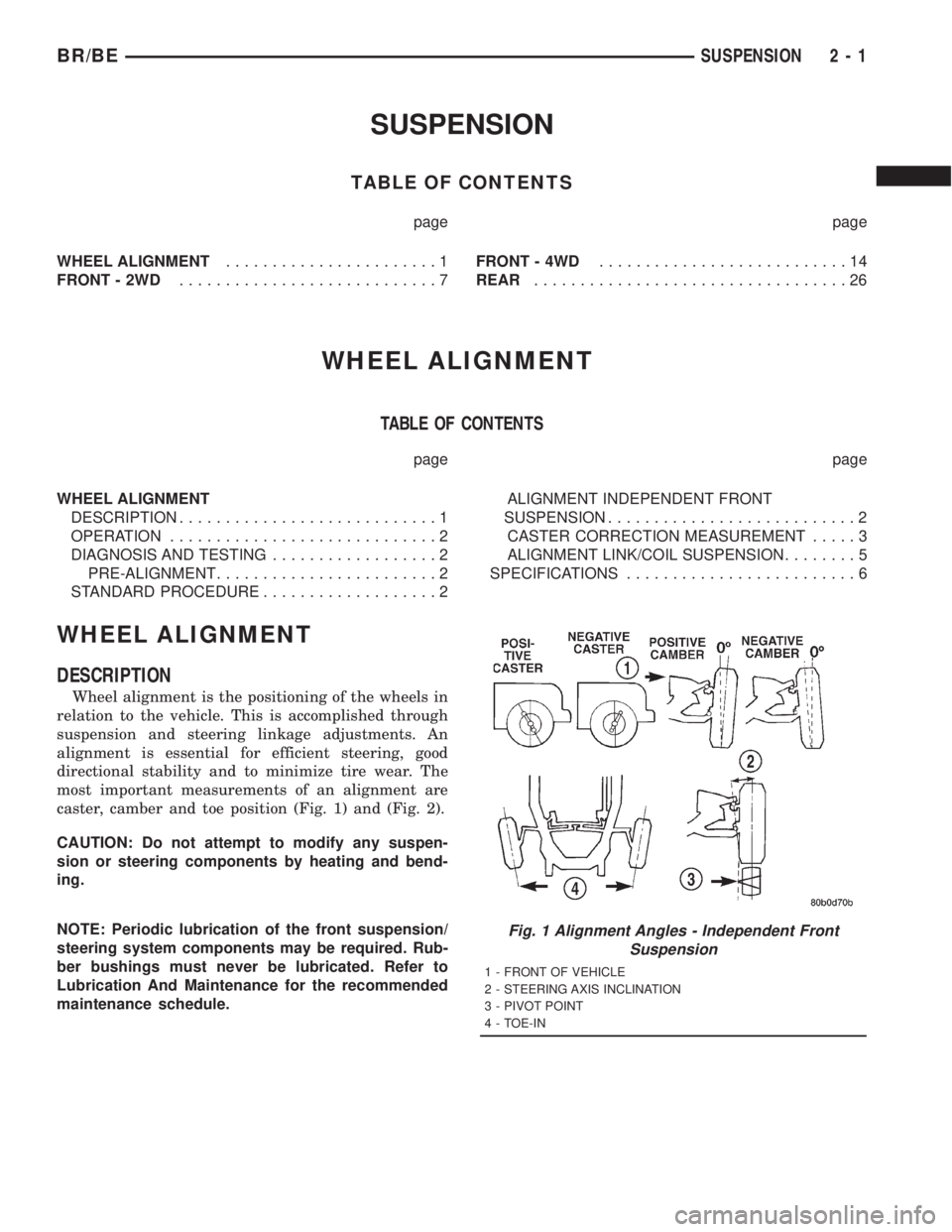
caster, camber and toe position (Fig. 1) and (Fig. 2).
CAUTION: Do not attempt to modify any suspen-
sion or steering components by heating and bend-
ing.
NOTE: Periodic lubrication of the front suspension/
steering system components may be required. Rub-
ber bushings must never be lubricated. Refer to
Lubrication And Maintenance for the recommended
maintenance schedule.
Fig. 1 Alignment Angles - Independent Front
Suspension
1 - FRONT OF VEHICLE
2 - STEERING AXIS INCLINATION
3 - PIVOT POINT
4 - TOE-IN
BR/BESUSPENSION 2 - 1
Page 343 of 2889
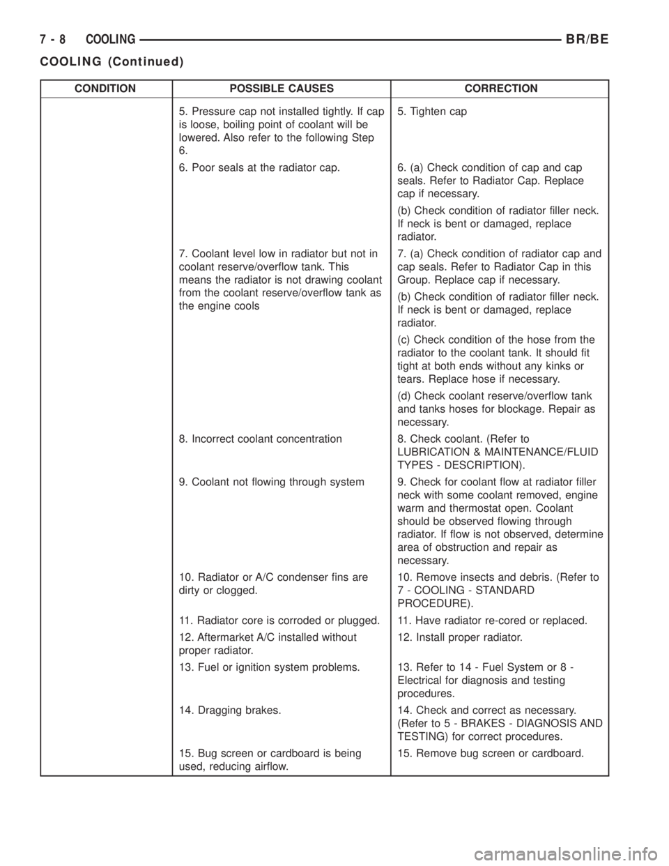
CONDITION POSSIBLE CAUSES CORRECTION
5. Pressure cap not installed tightly. If cap
is loose, boiling point of coolant will be
lowered. Also refer to the following Step
6.5. Tighten cap
6. Poor seals at the radiator cap. 6. (a) Check condition of cap and cap
seals. Refer to Radiator Cap. Replace
cap if necessary.
(b) Check condition of radiator filler neck.
If neck is bent or damaged, replace
radiator.
7. Coolant level low in radiator but not in
coolant reserve/overflow tank. This
means the radiator is not drawing coolant
from the coolant reserve/overflow tank as
the engine cools7. (a) Check condition of radiator cap and
cap seals. Refer to Radiator Cap in this
Group. Replace cap if necessary.
(b) Check condition of radiator filler neck.
If neck is bent or damaged, replace
radiator.
(c) Check condition of the hose from the
radiator to the coolant tank. It should fit
tight at both ends without any kinks or
tears. Replace hose if necessary.
(d) Check coolant reserve/overflow tank
and tanks hoses for blockage. Repair as
necessary.
8. Incorrect coolant concentration 8. Check coolant. (Refer to
LUBRICATION & MAINTENANCE/FLUID
TYPES - DESCRIPTION).
9. Coolant not flowing through system 9. Check for coolant flow at radiator filler
neck with some coolant removed, engine
warm and thermostat open. Coolant
should be observed flowing through
radiator. If flow is not observed, determine
area of obstruction and repair as
necessary.
10. Radiator or A/C condenser fins are
dirty or clogged.10. Remove insects and debris. (Refer to
7 - COOLING - STANDARD
PROCEDURE).
11. Radiator core is corroded or plugged. 11. Have radiator re-cored or replaced.
12. Aftermarket A/C installed without
proper radiator.12. Install proper radiator.
13. Fuel or ignition system problems. 13. Refer to 14 - Fuel System or 8 -
Electrical for diagnosis and testing
procedures.
14. Dragging brakes. 14. Check and correct as necessary.
(Refer to 5 - BRAKES - DIAGNOSIS AND
TESTING) for correct procedures.
15. Bug screen or cardboard is being
used, reducing airflow.15. Remove bug screen or cardboard.
7 - 8 COOLINGBR/BE
COOLING (Continued)
Page 345 of 2889
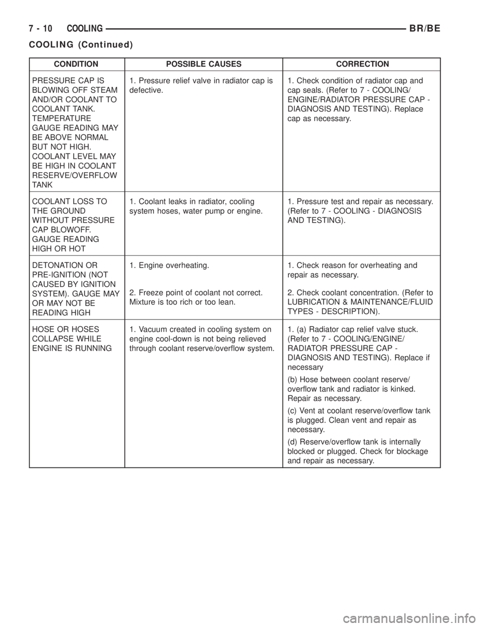
CONDITION POSSIBLE CAUSES CORRECTION
PRESSURE CAP IS
BLOWING OFF STEAM
AND/OR COOLANT TO
COOLANT TANK.
TEMPERATURE
GAUGE READING MAY
BE ABOVE NORMAL
BUT NOT HIGH.
COOLANT LEVEL MAY
BE HIGH IN COOLANT
RESERVE/OVERFLOW
TANK1. Pressure relief valve in radiator cap is
defective.1. Check condition of radiator cap and
cap seals. (Refer to 7 - COOLING/
ENGINE/RADIATOR PRESSURE CAP -
DIAGNOSIS AND TESTING). Replace
cap as necessary.
COOLANT LOSS TO
THE GROUND
WITHOUT PRESSURE
CAP BLOWOFF.
GAUGE READING
HIGH OR HOT1. Coolant leaks in radiator, cooling
system hoses, water pump or engine.1. Pressure test and repair as necessary.
(Refer to 7 - COOLING - DIAGNOSIS
AND TESTING).
DETONATION OR
PRE-IGNITION (NOT
CAUSED BY IGNITION
SYSTEM). GAUGE MAY
OR MAY NOT BE
READING HIGH1. Engine overheating. 1. Check reason for overheating and
repair as necessary.
2. Freeze point of coolant not correct.
Mixture is too rich or too lean.2. Check coolant concentration. (Refer to
LUBRICATION & MAINTENANCE/FLUID
TYPES - DESCRIPTION).
HOSE OR HOSES
COLLAPSE WHILE
ENGINE IS RUNNING1. Vacuum created in cooling system on
engine cool-down is not being relieved
through coolant reserve/overflow system.1. (a) Radiator cap relief valve stuck.
(Refer to 7 - COOLING/ENGINE/
RADIATOR PRESSURE CAP -
DIAGNOSIS AND TESTING). Replace if
necessary
(b) Hose between coolant reserve/
overflow tank and radiator is kinked.
Repair as necessary.
(c) Vent at coolant reserve/overflow tank
is plugged. Clean vent and repair as
necessary.
(d) Reserve/overflow tank is internally
blocked or plugged. Check for blockage
and repair as necessary.
7 - 10 COOLINGBR/BE
COOLING (Continued)
Page 347 of 2889
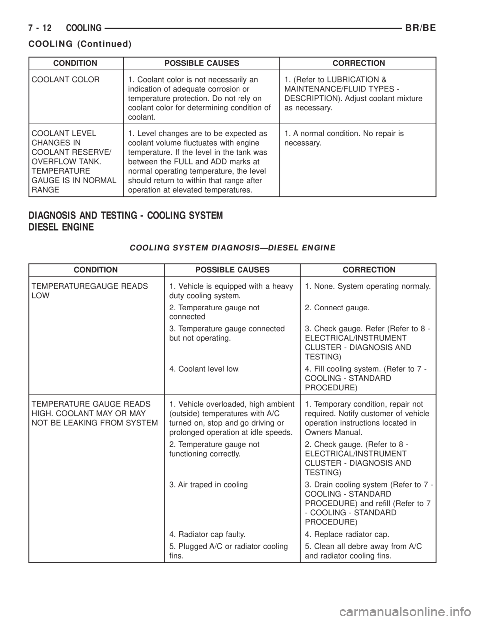
CONDITION POSSIBLE CAUSES CORRECTION
COOLANT COLOR 1. Coolant color is not necessarily an
indication of adequate corrosion or
temperature protection. Do not rely on
coolant color for determining condition of
coolant.1. (Refer to LUBRICATION &
MAINTENANCE/FLUID TYPES -
DESCRIPTION). Adjust coolant mixture
as necessary.
COOLANT LEVEL
CHANGES IN
COOLANT RESERVE/
OVERFLOW TANK.
TEMPERATURE
GAUGE IS IN NORMAL
RANGE1. Level changes are to be expected as
coolant volume fluctuates with engine
temperature. If the level in the tank was
between the FULL and ADD marks at
normal operating temperature, the level
should return to within that range after
operation at elevated temperatures.1. A normal condition. No repair is
necessary.
DIAGNOSIS AND TESTING - COOLING SYSTEM
DIESEL ENGINE
COOLING SYSTEM DIAGNOSISÐDIESEL ENGINE
CONDITION POSSIBLE CAUSES CORRECTION
TEMPERATUREGAUGE READS
LOW1. Vehicle is equipped with a heavy
duty cooling system.1. None. System operating normaly.
2. Temperature gauge not
connected2. Connect gauge.
3. Temperature gauge connected
but not operating.3. Check gauge. Refer (Refer to 8 -
ELECTRICAL/INSTRUMENT
CLUSTER - DIAGNOSIS AND
TESTING)
4. Coolant level low. 4. Fill cooling system. (Refer to 7 -
COOLING - STANDARD
PROCEDURE)
TEMPERATURE GAUGE READS
HIGH. COOLANT MAY OR MAY
NOT BE LEAKING FROM SYSTEM1. Vehicle overloaded, high ambient
(outside) temperatures with A/C
turned on, stop and go driving or
prolonged operation at idle speeds.1. Temporary condition, repair not
required. Notify customer of vehicle
operation instructions located in
Owners Manual.
2. Temperature gauge not
functioning correctly.2. Check gauge. (Refer to 8 -
ELECTRICAL/INSTRUMENT
CLUSTER - DIAGNOSIS AND
TESTING)
3. Air traped in cooling 3. Drain cooling system (Refer to 7 -
COOLING - STANDARD
PROCEDURE) and refill (Refer to 7
- COOLING - STANDARD
PROCEDURE)
4. Radiator cap faulty. 4. Replace radiator cap.
5. Plugged A/C or radiator cooling
fins.5. Clean all debre away from A/C
and radiator cooling fins.
7 - 12 COOLINGBR/BE
COOLING (Continued)
Page 358 of 2889
BELT TENSIONERS - 5.9L
DIESEL
DESCRIPTION
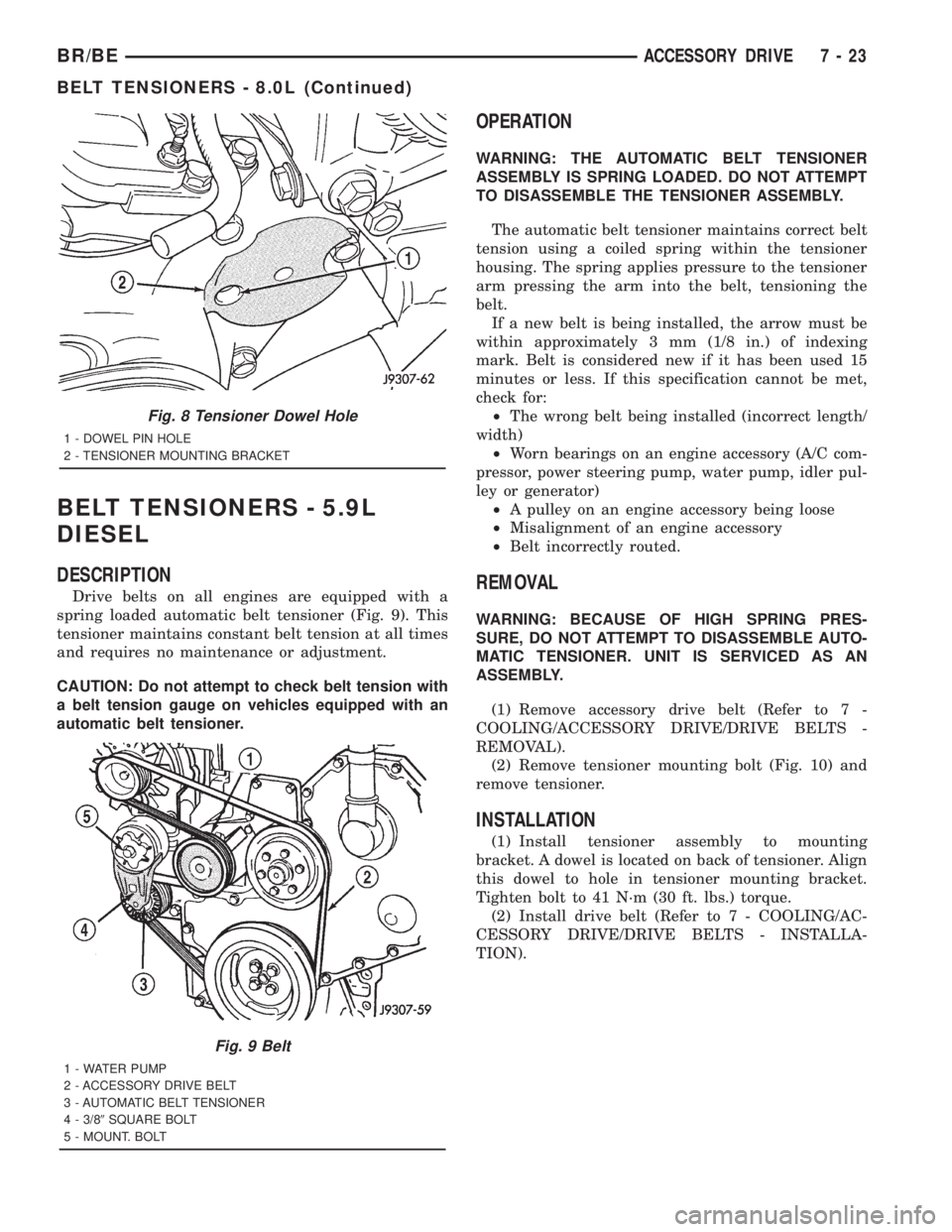
Drive belts on all engines are equipped with a
spring loaded automatic belt tensioner (Fig. 9). This
tensioner maintains constant belt tension at all times
and requires no maintenance or adjustment.
CAUTION: Do not attempt to check belt tension with
a belt tension gauge on vehicles equipped with an
automatic belt tensioner.
OPERATION
WARNING: THE AUTOMATIC BELT TENSIONER
ASSEMBLY IS SPRING LOADED. DO NOT ATTEMPT
TO DISASSEMBLE THE TENSIONER ASSEMBLY.
The automatic belt tensioner maintains correct belt
tension using a coiled spring within the tensioner
housing. The spring applies pressure to the tensioner
arm pressing the arm into the belt, tensioning the
belt.
If a new belt is being installed, the arrow must be
within approximately 3 mm (1/8 in.) of indexing
mark. Belt is considered new if it has been used 15
minutes or less. If this specification cannot be met,
check for:
²The wrong belt being installed (incorrect length/
width)
²Worn bearings on an engine accessory (A/C com-
pressor, power steering pump, water pump, idler pul-
ley or generator)
²A pulley on an engine accessory being loose
²Misalignment of an engine accessory
²Belt incorrectly routed.
REMOVAL
WARNING: BECAUSE OF HIGH SPRING PRES-
SURE, DO NOT ATTEMPT TO DISASSEMBLE AUTO-
MATIC TENSIONER. UNIT IS SERVICED AS AN
ASSEMBLY.
(1) Remove accessory drive belt (Refer to 7 -
COOLING/ACCESSORY DRIVE/DRIVE BELTS -
REMOVAL).
(2) Remove tensioner mounting bolt (Fig. 10) and
remove tensioner.
INSTALLATION
(1) Install tensioner assembly to mounting
bracket. A dowel is located on back of tensioner. Align
this dowel to hole in tensioner mounting bracket.
Tighten bolt to 41 N´m (30 ft. lbs.) torque.
(2) Install drive belt (Refer to 7 - COOLING/AC-
CESSORY DRIVE/DRIVE BELTS - INSTALLA-
TION).
Fig. 8 Tensioner Dowel Hole
1 - DOWEL PIN HOLE
2 - TENSIONER MOUNTING BRACKET
Fig. 9 Belt
1 - WATER PUMP
2 - ACCESSORY DRIVE BELT
3 - AUTOMATIC BELT TENSIONER
4 - 3/89SQUARE BOLT
5 - MOUNT. BOLT
BR/BEACCESSORY DRIVE 7 - 23
BELT TENSIONERS - 8.0L (Continued)
Page 473 of 2889

For battery system maintenance schedules and
jump starting procedures, see the owner's manual in
the vehicle glove box. Optionally, refer to Lubrication
and Maintenance for the recommended battery main-
tenance schedules and for the proper battery jump
starting procedures. While battery charging can be
considered a maintenance procedure, the battery
charging procedures and related information are
located in the standard procedures section of this ser-
vice manual. This was done because the battery must
be fully-charged before any battery system diagnosis
or testing procedures can be performed. Refer to
Standard procedures for the proper battery charging
procedures.
OPERATION
The battery system is designed to provide a safe,
efficient, reliable and mobile means of producing,
delivering and storing electrical energy. This electri-
cal energy is required to operate the engine starting
system, as well as to operate many of the other vehi-
cle accessory systems for limited durations while the
engine and/or the charging system are not operating.
The battery system is also designed to provide a
reserve of electrical energy to supplement the charg-
ing system for short durations while the engine is
running and the electrical current demands of the
vehicle exceed the output of the charging system. In
addition to producing, delivering, and storing electri-
cal energy for the vehicle, the battery system serves
as a capacitor and voltage stabilizer for the vehicle
electrical system. It absorbs most abnormal or tran-
sient voltages caused by the switching of any of the
electrical components or circuits in the vehicle.
DIAGNOSIS AND TESTING - BATTERY SYSTEM
The battery, starting, and charging systems in the
vehicle operate with one another and must be tested
as a single complete system. In order for the engine
to start and the battery to charge properly, all of the
components that are used in these systems must per-
form within specifications. It is important that the
battery, starting, and charging systems be thoroughly
tested and inspected any time a battery needs to be
charged or replaced. The cause of abnormal battery
discharge, overcharging or early battery failure must
be diagnosed and corrected before a battery is
replaced and before a vehicle is returned to service.
The service information for these systems has been
separated within this service manual to make it eas-
ier to locate the specific information you are seeking.
However, when attempting to diagnose any of these
systems, it is important that you keep their interde-
pendency in mind.
The diagnostic procedures used for the battery,
starting, and charging systems include the most
basic conventional diagnostic methods, to the more
sophisticated On-Board Diagnostics (OBD) built into
the Powertrain Control Module (PCM). Use of an
induction-type milliampere ammeter, a volt/ohmme-
ter, a battery charger, a carbon pile rheostat (load
tester) and a 12-volt test lamp may be required. All
OBD-sensed systems are monitored by the PCM.
Each monitored circuit is assigned a Diagnostic Trou-
ble Code (DTC). The PCM will store a DTC in elec-
tronic memory for any failure it detects. Refer to
Charging System for the proper charging system on-
board diagnostic test procedures.
8F - 2 BATTERY SYSTEMBR/BE
BATTERY SYSTEM (Continued)
Page 476 of 2889
²A faulty or incorrect starting system component.
Refer to Starting System for the proper starting sys-
tem diagnosis and testing procedures.
²A faulty or incorrect battery. Refer to Standard
Procedures for the proper battery diagnosis and test-
ing procedures. Refer to Battery System Specifica-
tions for the proper specifications.
CLEANING
The following information details the recommended
cleaning procedures for the battery and related com-
ponents. In addition to the maintenance schedules
found in this service manual and the owner's man-
ual, it is recommended that these procedures be per-
formed any time the battery or related components
must be removed for vehicle service.
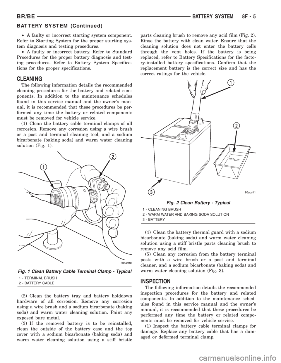
(1) Clean the battery cable terminal clamps of all
corrosion. Remove any corrosion using a wire brush
or a post and terminal cleaning tool, and a sodium
bicarbonate (baking soda) and warm water cleaning
solution (Fig. 1).
(2) Clean the battery tray and battery holddown
hardware of all corrosion. Remove any corrosion
using a wire brush and a sodium bicarbonate (baking
soda) and warm water cleaning solution. Paint any
exposed bare metal.
(3) If the removed battery is to be reinstalled,
clean the outside of the battery case and the top
cover with a sodium bicarbonate (baking soda) and
warm water cleaning solution using a stiff bristleparts cleaning brush to remove any acid film (Fig. 2).
Rinse the battery with clean water. Ensure that the
cleaning solution does not enter the battery cells
through the vent holes. If the battery is being
replaced, refer to Battery Specifications for the facto-
ry-installed battery specifications. Confirm that the
replacement battery is the correct size and has the
correct ratings for the vehicle.
(4) Clean the battery thermal guard with a sodium
bicarbonate (baking soda) and warm water cleaning
solution using a stiff bristle parts cleaning brush to
remove any acid film.
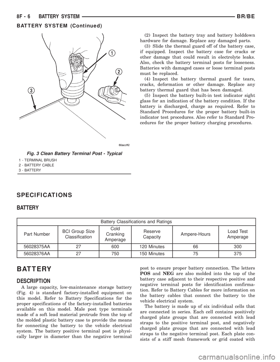
(5) Clean any corrosion from the battery terminal
posts with a wire brush or a post and terminal
cleaner, and a sodium bicarbonate (baking soda) and
warm water cleaning solution (Fig. 3).
INSPECTION
The following information details the recommended
inspection procedures for the battery and related
components. In addition to the maintenance sched-
ules found in this service manual and the owner's
manual, it is recommended that these procedures be
performed any time the battery or related compo-
nents must be removed for vehicle service.
(1) Inspect the battery cable terminal clamps for
damage. Replace any battery cable that has a dam-
aged or deformed terminal clamp.
Fig. 1 Clean Battery Cable Terminal Clamp - Typical
1 - TERMINAL BRUSH
2 - BATTERY CABLE
Fig. 2 Clean Battery - Typical
1 - CLEANING BRUSH
2 - WARM WATER AND BAKING SODA SOLUTION
3 - BATTERY
BR/BEBATTERY SYSTEM 8F - 5
BATTERY SYSTEM (Continued)
Page 477 of 2889
(2) Inspect the battery tray and battery holddown
hardware for damage. Replace any damaged parts.
(3) Slide the thermal guard off of the battery case,
if equipped. Inspect the battery case for cracks or
other damage that could result in electrolyte leaks.
Also, check the battery terminal posts for looseness.
Batteries with damaged cases or loose terminal posts
must be replaced.
(4) Inspect the battery thermal guard for tears,
cracks, deformation or other damage. Replace any
battery thermal guard that has been damaged.
(5) Inspect the battery built-in test indicator sight
glass for an indication of the battery condition. If the
battery is discharged, charge as required. Refer to
Standard Procedures for the proper battery built-in
indicator test procedures. Also refer to Standard Pro-
cedures for the proper battery charging procedures.
SPECIFICATIONS
BATTERY
Battery Classifications and Ratings
Part NumberBCI Group Size
ClassificationCold
Cranking
AmperageReserve
CapacityAmpere-HoursLoad Test
Amperage
56028375AA 27 600 120 Minutes 66 300
56028376AA 27 750 150 Minutes 75 375
BATTERY
DESCRIPTION
A large capacity, low-maintenance storage battery
(Fig. 4) is standard factory-installed equipment on
this model. Refer to Battery Specifications for the
proper specifications of the factory-installed batteries
available on this model. Male post type terminals
made of a soft lead material protrude from the top of
the molded plastic battery case to provide the means
for connecting the battery to the vehicle electrical
system. The battery positive terminal post is physi-
cally larger in diameter than the negative terminalpost to ensure proper battery connection. The letters
POSandNEGare also molded into the top of the
battery case adjacent to their respective positive and
negative terminal posts for identification confirma-
tion. Refer to Battery Cables for more information on
the battery cables that connect the battery to the
vehicle electrical system.
The battery is made up of six individual cells that
are connected in series. Each cell contains positively
charged plate groups that are connected with lead
straps to the positive terminal post, and negatively
charged plate groups that are connected with lead
straps to the negative terminal post. Each plate con-
sists of a stiff mesh framework or grid coated with
Fig. 3 Clean Battery Terminal Post - Typical
1 - TERMINAL BRUSH
2 - BATTERY CABLE
3 - BATTERY
8F - 6 BATTERY SYSTEMBR/BE
BATTERY SYSTEM (Continued)