2001 DODGE RAM maintenance
[x] Cancel search: maintenancePage 1195 of 2889
(6) Add oil only if level is below the ADD mark on
dipstick.
ENGINE OIL CHANGE:
Change engine oil at mileage and time intervals
described in the Maintenance Schedule. This infor-
mation can be found in the owner's manual.
TO CHANGE ENGINE OIL
Run engine until achieving normal operating tem-
perature.
(1) Position the vehicle on a level surface and turn
engine off.
(2) Hoist vehicle.
(3) Remove oil fill cap.
(4) Place a suitable drain pan under crankcase
drain.
(5) Remove drain plug from crankcase and allow
oil to drain into pan. Inspect drain plug threads for
stretching or other damage. Replace drain plug and
gasket if damaged.
(6) Install drain plug in crankcase.
(7) Change oil filter (Refer to 9 - ENGINE/LUBRI-
CATION/OIL FILTER - REMOVAL).
(8) Lower vehicle and fill crankcase with specified
type (Refer to LUBRICATION & MAINTENANCE/
FLUID TYPES - DESCRIPTION) and amount of
engine oil (Refer to LUBRICATION & MAINTE-
NANCE - SPECIFICATIONS).
(9) Install oil fill cap.
(10) Start engine and inspect for leaks.
(11) Stop engine and inspect oil level.
OIL FILTER
REMOVAL
All engines are equipped with a high quality full-
flow, disposable type oil filter. DaimlerChrysler Cor-
poration recommends a Mopartor equivalent oil
filter be used.
(1) Position a drain pan under the oil filter.
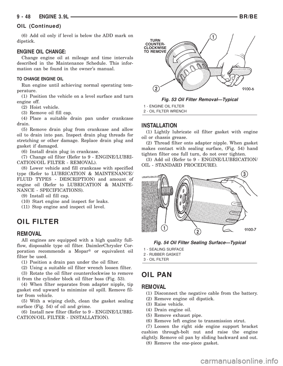
(2) Using a suitable oil filter wrench loosen filter.
(3) Rotate the oil filter counterclockwise to remove
it from the cylinder block oil filter boss (Fig. 53).
(4) When filter separates from adapter nipple, tip
gasket end upward to minimize oil spill. Remove fil-
ter from vehicle.
(5) With a wiping cloth, clean the gasket sealing
surface (Fig. 54) of oil and grime.
(6) Install new filter (Refer to 9 - ENGINE/LUBRI-
CATION/OIL FILTER - INSTALLATION).
INSTALLATION
(1) Lightly lubricate oil filter gasket with engine
oil or chassis grease.
(2) Thread filter onto adapter nipple. When gasket
makes contact with sealing surface, (Fig. 54) hand
tighten filter one full turn, do not over tighten.
(3) Add oil (Refer to 9 - ENGINE/LUBRICATION/
OIL - STANDARD PROCEDURE).
OIL PAN
REMOVAL
(1) Disconnect the negative cable from the battery.
(2) Remove engine oil dipstick.
(3) Raise vehicle.
(4) Drain engine oil.
(5) Remove exhaust pipe.
(6) Remove left engine to transmission strut.
(7) Loosen the right side engine support bracket
cushion through-bolt nut and raise the engine
slightly. Remove oil pan by sliding backward and out.
(8) Remove the one-piece gasket.
Fig. 53 Oil Filter RemovalÐTypical
1 - ENGINE OIL FILTER
2 - OIL FILTER WRENCH
Fig. 54 Oil Filter Sealing SurfaceÐTypical
1 - SEALING SURFACE
2 - RUBBER GASKET
3 - OIL FILTER
9 - 48 ENGINE 3.9LBR/BE
OIL (Continued)
Page 1208 of 2889
DIAGNOSIS AND TESTING-ENGINE DIAGNOSIS
- INTRODUCTION
Engine diagnosis is helpful in determining the
causes of malfunctions not detected and remedied by
routine maintenance.
These malfunctions may be classified as either
mechanical (e.g., a strange noise), or performance
(e.g., engine idles rough and stalls).
(Refer to 9 - ENGINE - DIAGNOSIS AND TEST-
ING - Preformance) or (Refer to 9 - ENGINE - DIAG-
NOSIS AND TESTING - Mechanical). Refer to 14 -
FUEL SYSTEM for fuel system diagnosis.Additional tests and diagnostic procedures may be
necessary for specific engine malfunctions that can-
not be isolated with the Service Diagnosis charts.
Information concerning additional tests and diagno-
sis is provided within the following:
²Cylinder Compression Pressure Test
²Cylinder Combustion Pressure Leakage Test
²Cylinder Head Gasket Failure Diagnosis
²Intake Manifold Leakage Diagnosis
²Lash Adjuster (Tappet) Noise Diagnosis
²Engine Oil Leak Inspection
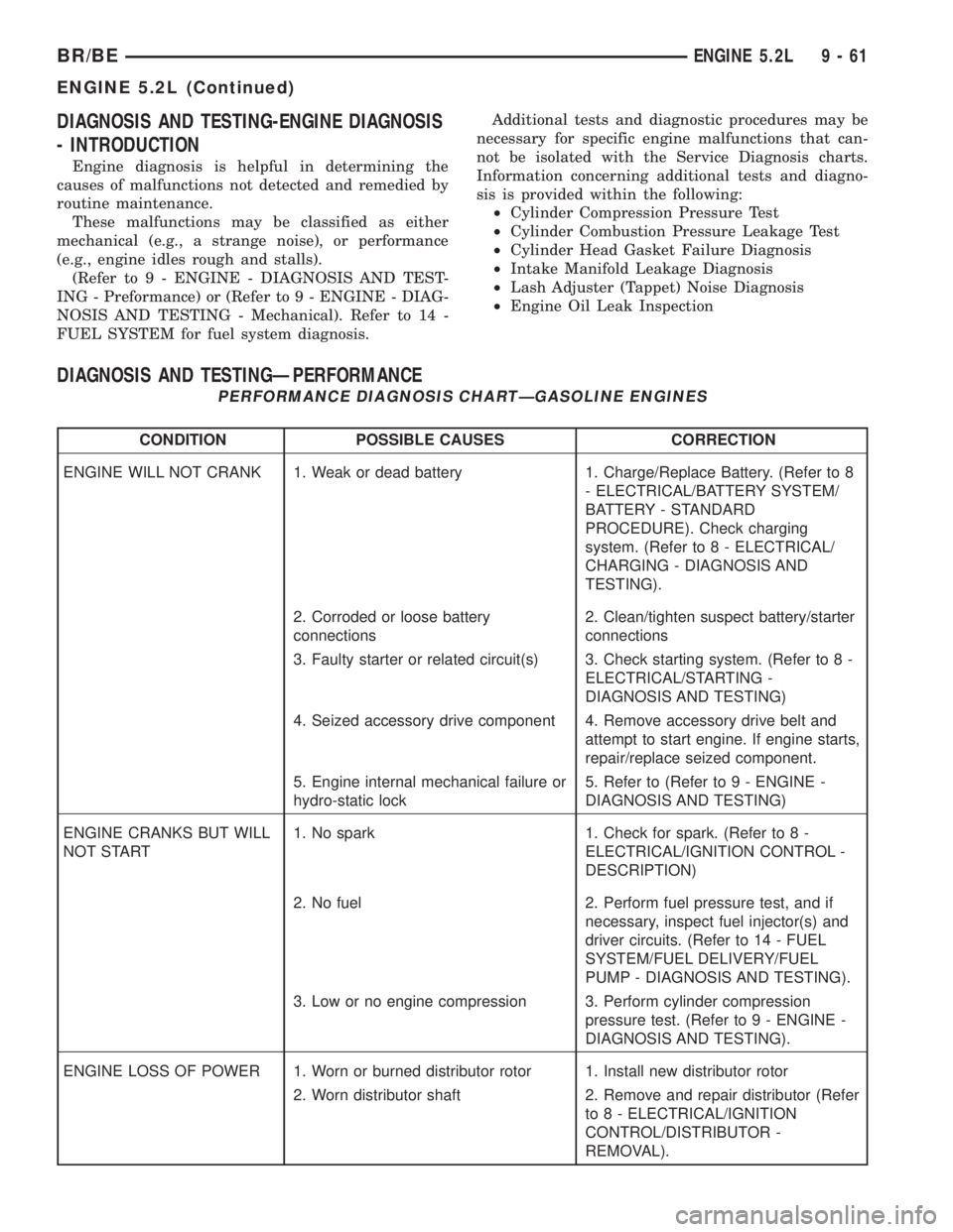
DIAGNOSIS AND TESTINGÐPERFORMANCE
PERFORMANCE DIAGNOSIS CHARTÐGASOLINE ENGINES
CONDITION POSSIBLE CAUSES CORRECTION
ENGINE WILL NOT CRANK 1. Weak or dead battery 1. Charge/Replace Battery. (Refer to 8
- ELECTRICAL/BATTERY SYSTEM/
BATTERY - STANDARD
PROCEDURE). Check charging
system. (Refer to 8 - ELECTRICAL/
CHARGING - DIAGNOSIS AND
TESTING).
2. Corroded or loose battery
connections2. Clean/tighten suspect battery/starter
connections
3. Faulty starter or related circuit(s) 3. Check starting system. (Refer to 8 -
ELECTRICAL/STARTING -
DIAGNOSIS AND TESTING)
4. Seized accessory drive component 4. Remove accessory drive belt and
attempt to start engine. If engine starts,
repair/replace seized component.
5. Engine internal mechanical failure or
hydro-static lock5. Refer to (Refer to 9 - ENGINE -
DIAGNOSIS AND TESTING)
ENGINE CRANKS BUT WILL
NOT START1. No spark 1. Check for spark. (Refer to 8 -
ELECTRICAL/IGNITION CONTROL -
DESCRIPTION)
2. No fuel 2. Perform fuel pressure test, and if
necessary, inspect fuel injector(s) and
driver circuits. (Refer to 14 - FUEL
SYSTEM/FUEL DELIVERY/FUEL
PUMP - DIAGNOSIS AND TESTING).
3. Low or no engine compression 3. Perform cylinder compression
pressure test. (Refer to 9 - ENGINE -
DIAGNOSIS AND TESTING).
ENGINE LOSS OF POWER 1. Worn or burned distributor rotor 1. Install new distributor rotor
2. Worn distributor shaft 2. Remove and repair distributor (Refer
to 8 - ELECTRICAL/IGNITION
CONTROL/DISTRIBUTOR -
REMOVAL).
BR/BEENGINE 5.2L 9 - 61
ENGINE 5.2L (Continued)
Page 1216 of 2889
(1) Perform the Fuel Pressure Release Procedure
(Refer to 14 - FUEL SYSTEM/FUEL DELIVERY -
STANDARD PROCEDURE).
(2) Disconnect the negative cable(s) from the bat-
tery.
(3) Inspect air cleaner, induction system, and
intake manifold to ensure system is dry and clear of
foreign material.
(4) Place a shop towel around the spark plugs to
catch any fluid that may possibly be under pressure
in the cylinder head. Remove the spark plugs.
(5) With all spark plugs removed, rotate the crank-
shaft using a breaker bar and socket.
(6) Identify the fluid in the cylinders (coolant, fuel,
oil, etc.).
(7) Be sure all fluid has been removed from the
cylinders.
(8) Repair engine or components as necessary to
prevent this problem from occurring again.
(9) Squirt a small amount of engine oil into the
cylinders to lubricate the walls. This will prevent
damage on restart.
(10) Install new spark plugs. Tighten the spark
plugs to 41 N´m (30 ft. lbs.) torque.
(11) Drain engine oil. Remove and discard the oil
filter.
(12) Install the drain plug. Tighten the plug to 34
N´m (25 ft. lbs.) torque.
(13) Install a new oil filter.
(14) Fill engine crankcase with the specified
amount and grade of oil. (Refer to LUBRICATION &
MAINTENANCE - SPECIFICATIONS).
(15) Connect the negative cable(s) to the battery.
(16) Start the engine and check for any leaks.
STANDARD PROCEDUREÐCYLINDER BORE
HONING
Before honing, stuff plenty of clean shop towels
under the bores and over the crankshaft to keep
abrasive materials from entering the crankshaft
area.
(1) Used carefully, the Cylinder Bore Sizing Hone
C-823, equipped with 220 grit stones, is the best tool
for this job. In addition to deglazing, it will reduce
taper and out-of-round, as well as removing light
scuffing, scoring and scratches. Usually, a few strokes
will clean up a bore and maintain the required lim-
its.
CAUTION: DO NOT use rigid type hones to remove
cylinder wall glaze.
(2) Deglazing of the cylinder walls may be done if
the cylinder bore is straight and round. Use a cylin-
der surfacing hone, Honing Tool C-3501, equipped
with 280 grit stones (C-3501-3810). about 20-60strokes, depending on the bore condition, will be suf-
ficient to provide a satisfactory surface. Using honing
oil C-3501-3880, or a light honing oil, available from
major oil distributors.
CAUTION: DO NOT use engine or transmission oil,
mineral spirits, or kerosene.
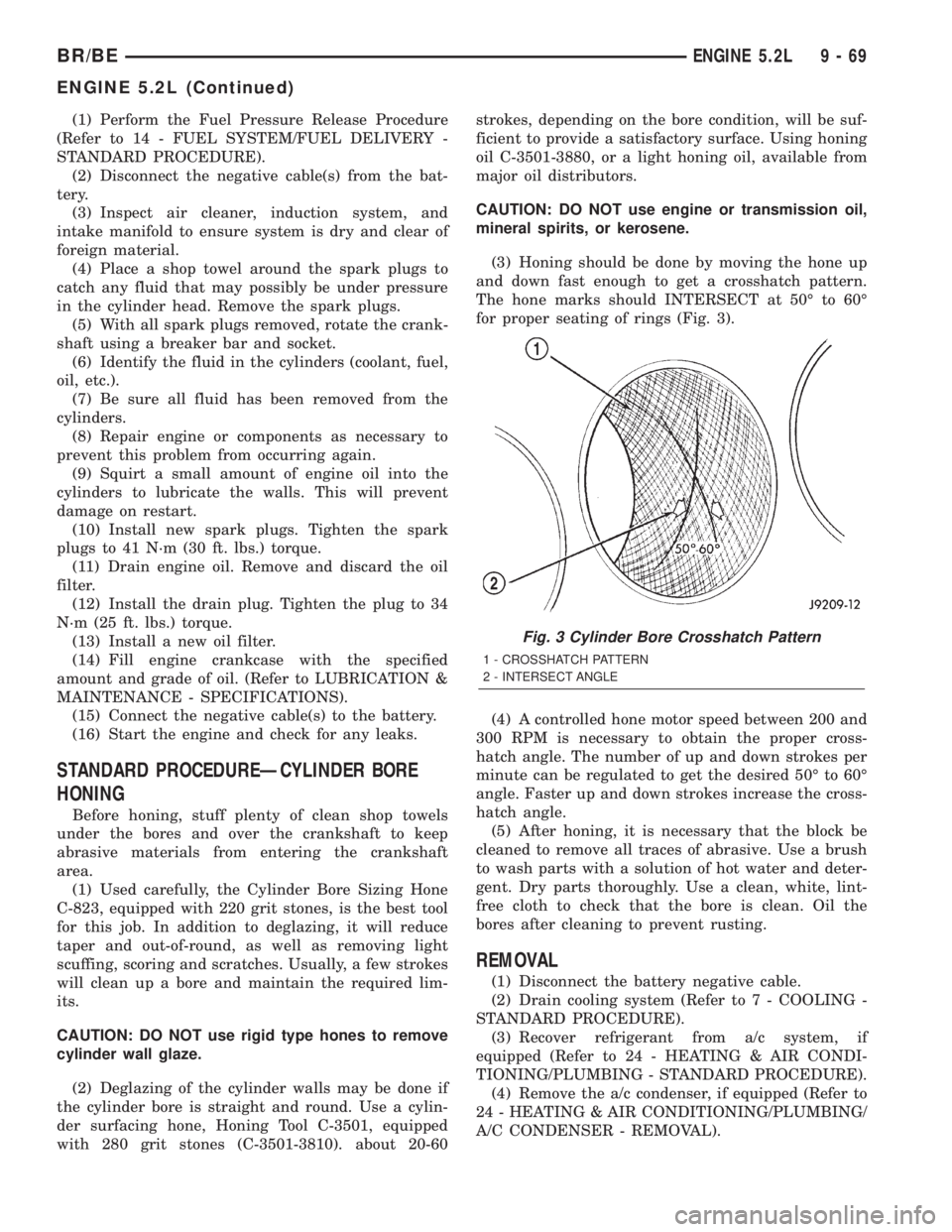
(3) Honing should be done by moving the hone up
and down fast enough to get a crosshatch pattern.
The hone marks should INTERSECT at 50É to 60É
for proper seating of rings (Fig. 3).
(4) A controlled hone motor speed between 200 and
300 RPM is necessary to obtain the proper cross-
hatch angle. The number of up and down strokes per
minute can be regulated to get the desired 50É to 60É
angle. Faster up and down strokes increase the cross-
hatch angle.
(5) After honing, it is necessary that the block be
cleaned to remove all traces of abrasive. Use a brush
to wash parts with a solution of hot water and deter-
gent. Dry parts thoroughly. Use a clean, white, lint-
free cloth to check that the bore is clean. Oil the
bores after cleaning to prevent rusting.
REMOVAL
(1) Disconnect the battery negative cable.
(2) Drain cooling system (Refer to 7 - COOLING -
STANDARD PROCEDURE).
(3) Recover refrigerant from a/c system, if
equipped (Refer to 24 - HEATING & AIR CONDI-
TIONING/PLUMBING - STANDARD PROCEDURE).
(4) Remove the a/c condenser, if equipped (Refer to
24 - HEATING & AIR CONDITIONING/PLUMBING/
A/C CONDENSER - REMOVAL).
Fig. 3 Cylinder Bore Crosshatch Pattern
1 - CROSSHATCH PATTERN
2 - INTERSECT ANGLE
BR/BEENGINE 5.2L 9 - 69
ENGINE 5.2L (Continued)
Page 1218 of 2889
(21) Using a new gasket, install throttle body
(Refer to 14 - FUEL SYSTEM/FUEL INJECTION/
THROTTLE BODY - INSTALLATION).
(22) Connect the throttle linkage (Refer to 14 -
FUEL SYSTEM/FUEL INJECTION/THROTTLE
CONTROL CABLE - INSTALLATION).
(23) Install the air cleaner resonator and duct
work..
(24) Install the generator and wire connections
(Refer to 8 - ELECTRICAL/CHARGING/GENERA-
TOR - INSTALLATION).
(25) Install a/c compressor and lines (Refer to 24 -
HEATING & AIR CONDITIONING/PLUMBING/A/C
COMPRESSOR - INSTALLATION).
(26) Install the accessory drive belt (Refer to 7 -
COOLING/ACCESSORY DRIVE/DRIVE BELTS -
INSTALLATION).
(27) Install upper radiator support crossmember.
(28) Install radiator (Refer to 7 - COOLING/EN-
GINE/RADIATOR - INSTALLATION).
(29) Connect the radiator lower hose.
(30) Connect the transmission oil cooler lines to
the radiator.
(31) Install the fan shroud.(32) Install the fan (Refer to 7 - COOLING/EN-
GINE/RADIATOR FAN - INSTALLATION).
(33) Connect the radiator upper hose.
(34) Install the washer bottle.
(35) Install the transmission oil cooler (Refer to 7 -
COOLING/TRANSMISSION/TRANS COOLER -
INSTALLATION).
(36) Connect the transmission cooler lines.
(37) If equipped, install the condenser (Refer to 24
- HEATING & AIR CONDITIONING/PLUMBING/
A/C CONDENSER - INSTALLATION).
(38) Evacuate and charge the air conditioning sys-
tem, if equipped (Refer to 24 - HEATING & AIR
CONDITIONING/PLUMBING - STANDARD PRO-
CEDURE).
(39) Add engine oil to crankcase (Refer to LUBRI-
CATION & MAINTENANCE/FLUID TYPES - SPEC-
IFICATIONS).
(40) Fill cooling system (Refer to 7 - COOLING -
STANDARD PROCEDURE).
(41) Connect battery negative cable.
(42) Start engine and inspect for leaks.
(43) Road test vehicle.
BR/BEENGINE 5.2L 9 - 71
ENGINE 5.2L (Continued)
Page 1252 of 2889
(5) Remove dipstick, with handle held above the
tip, take oil level reading.
(6) Add oil only if level is below the ADD mark on
dipstick.
ENGINE OIL CHANGE
Change engine oil at mileage and time intervals
described in the Maintenance Schedule. This infor-
mation can be found in the owner's manual.
TO CHANGE ENGINE OIL
Run engine until achieving normal operating tem-
perature.
(1) Position the vehicle on a level surface and turn
engine off.
(2) Hoist vehicle.
(3) Remove oil fill cap.
(4) Place a suitable drain pan under crankcase
drain.
(5) Remove drain plug from crankcase and allow
oil to drain into pan. Inspect drain plug threads for
stretching or other damage. Replace drain plug and
gasket if damaged.
(6) Install drain plug in crankcase.
(7) Change oil filter (Refer to 9 - ENGINE/LUBRI-
CATION/OIL FILTER - REMOVAL).
(8) Lower vehicle and fill crankcase with specified
type (Refer to LUBRICATION & MAINTENANCE/
FLUID TYPES - DESCRIPTION) and amount of
engine oil (Refer to LUBRICATION & MAINTE-
NANCE - SPECIFICATIONS).
(9) Install oil fill cap.
(10) Start engine and inspect for leaks.
(11) Stop engine and inspect oil level.
OIL FILTER
REMOVAL
All engines are equipped with a high quality full-
flow, disposable type oil filter. DaimlerChrysler Cor-
poration recommends a Mopartor equivalent oil
filter be used.
(1) Position a drain pan under the oil filter.
(2) Using a suitable oil filter wrench loosen filter.
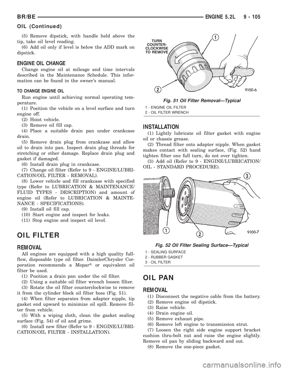
(3) Rotate the oil filter counterclockwise to remove
it from the cylinder block oil filter boss (Fig. 51).
(4) When filter separates from adapter nipple, tip
gasket end upward to minimize oil spill. Remove fil-
ter from vehicle.
(5) With a wiping cloth, clean the gasket sealing
surface (Fig. 54) of oil and grime.
(6) Install new filter (Refer to 9 - ENGINE/LUBRI-
CATION/OIL FILTER - INSTALLATION).
INSTALLATION
(1) Lightly lubricate oil filter gasket with engine
oil or chassis grease.
(2) Thread filter onto adapter nipple. When gasket
makes contact with sealing surface, (Fig. 52) hand
tighten filter one full turn, do not over tighten.
(3) Add oil (Refer to 9 - ENGINE/LUBRICATION/
OIL - STANDARD PROCEDURE).
OIL PAN
REMOVAL
(1) Disconnect the negative cable from the battery.
(2) Remove engine oil dipstick.
(3) Raise vehicle.
(4) Drain engine oil.
(5) Remove exhaust pipe.
(6) Remove left engine to transmission strut.
(7) Loosen the right side engine support bracket
cushion thru-bolt nut and raise the engine slightly.
Remove oil pan by sliding backward and out.
(8) Remove the one-piece gasket.
Fig. 51 Oil Filter RemovalÐTypical
1 - ENGINE OIL FILTER
2 - OIL FILTER WRENCH
Fig. 52 Oil Filter Sealing SurfaceÐTypical
1 - SEALING SURFACE
2 - RUBBER GASKET
3 - OIL FILTER
BR/BEENGINE 5.2L 9 - 105
OIL (Continued)
Page 1265 of 2889
DIAGNOSIS AND TESTINGÐENGINE
DIAGNOSIS - INTRODUCTION
Engine diagnosis is helpful in determining the
causes of malfunctions not detected and remedied by
routine maintenance.
These malfunctions may be classified as either
mechanical (e.g., a strange noise), or performance
(e.g., engine idles rough and stalls).
(Refer to 9 - ENGINE - DIAGNOSIS AND TEST-
ING - Preformance) or (Refer to 9 - ENGINE - DIAG-
NOSIS AND TESTING - Mechanical). Refer to 14 -
FUEL SYSTEM for fuel system diagnosis.Additional tests and diagnostic procedures may be
necessary for specific engine malfunctions that can-
not be isolated with the Service Diagnosis charts.
Information concerning additional tests and diagno-
sis is provided within the following:
²Cylinder Compression Pressure Test
²Cylinder Combustion Pressure Leakage Test
²Cylinder Head Gasket Failure Diagnosis
²Intake Manifold Leakage Diagnosis
²Lash Adjuster (Tappet) Noise Diagnosis
²Engine Oil Leak Inspection
DIAGNOSIS AND TESTINGÐPERFORMANCE
PERFORMANCE DIAGNOSIS CHARTÐGASOLINE ENGINES
CONDITION POSSIBLE CAUSES CORRECTION
ENGINE WILL NOT CRANK 1. Weak or dead battery 1. Charge/Replace Battery. (Refer to
8 - ELECTRICAL/BATTERY
SYSTEM/BATTERY - STANDARD
PROCEDURE). Check charging
system. (Refer to 8 - ELECTRICAL/
CHARGING - DIAGNOSIS AND
TESTING).
2. Corroded or loose battery
connections2. Clean/tighten suspect battery/
starter connections
3. Faulty starter or related circuit(s) 3. Check starting system. (Refer to
8 - ELECTRICAL/STARTING -
DIAGNOSIS AND TESTING)
4. Seized accessory drive
component4. Remove accessory drive belt and
attempt to start engine. If engine
starts, repair/replace seized
component.
5. Engine internal mechanical
failure or hydro-static lock5. Refer to (Refer to 9 - ENGINE -
DIAGNOSIS AND TESTING)
ENGINE CRANKS BUT WILL NOT
START1. No spark 1. Check for spark. (Refer to 8 -
ELECTRICAL/IGNITION CONTROL
- DESCRIPTION)
2. No fuel 2. Perform fuel pressure test, and if
necessary, inspect fuel injector(s)
and driver circuits. (Refer to 14 -
FUEL SYSTEM/FUEL DELIVERY/
FUEL PUMP - DIAGNOSIS AND
TESTING).
3. Low or no engine compression 3. Perform cylinder compression
pressure test. (Refer to 9 - ENGINE
- DIAGNOSIS AND TESTING).
9 - 118 ENGINE 5.9LBR/BE
ENGINE 5.9L (Continued)
Page 1273 of 2889
(1) Perform the Fuel Pressure Release Procedure
(Refer to 14 - FUEL SYSTEM/FUEL DELIVERY -
STANDARD PROCEDURE).
(2) Disconnect the negative cable(s) from the bat-
tery.
(3) Inspect air cleaner, induction system, and
intake manifold to ensure system is dry and clear of
foreign material.
(4) Place a shop towel around the spark plugs to
catch any fluid that may possibly be under pressure
in the cylinder head. Remove the spark plugs.
(5) With all spark plugs removed, rotate the crank-
shaft using a breaker bar and socket.
(6) Identify the fluid in the cylinders (coolant, fuel,
oil, etc.).
(7) Be sure all fluid has been removed from the
cylinders.
(8) Repair engine or components as necessary to
prevent this problem from occurring again.
(9) Squirt a small amount of engine oil into the
cylinders to lubricate the walls. This will prevent
damage on restart.
(10) Install new spark plugs. Tighten the spark
plugs to 41 N´m (30 ft. lbs.) torque.
(11) Drain engine oil. Remove and discard the oil
filter.
(12) Install the drain plug. Tighten the plug to 34
N´m (25 ft. lbs.) torque.
(13) Install a new oil filter.
(14) Fill engine crankcase with the specified
amount and grade of oil. (Refer to LUBRICATION &
MAINTENANCE - SPECIFICATIONS).
(15) Connect the negative cable(s) to the battery.
(16) Start the engine and check for any leaks.
STANDARD PROCEDUREÐCYLINDER BORE
HONING
Before honing, stuff plenty of clean shop towels
under the bores and over the crankshaft to keep
abrasive materials from entering the crankshaft
area.
(1) Used carefully, the Cylinder Bore Sizing Hone
C-823, equipped with 220 grit stones, is the best tool
for this job. In addition to deglazing, it will reduce
taper and out-of-round, as well as removing light
scuffing, scoring and scratches. Usually, a few strokes
will clean up a bore and maintain the required lim-
its.
CAUTION: DO NOT use rigid type hones to remove
cylinder wall glaze.
(2) Deglazing of the cylinder walls may be done if
the cylinder bore is straight and round. Use a cylin-
der surfacing hone, Honing Tool C-3501, equipped
with 280 grit stones (C-3501-3810). about 20-60strokes, depending on the bore condition, will be suf-
ficient to provide a satisfactory surface. Using honing
oil C-3501-3880, or a light honing oil, available from
major oil distributors.
CAUTION: DO NOT use engine or transmission oil,
mineral spirits, or kerosene.
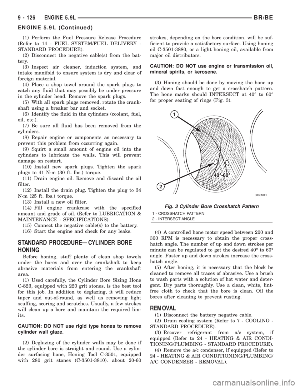
(3) Honing should be done by moving the hone up
and down fast enough to get a crosshatch pattern.
The hone marks should INTERSECT at 40É to 60É
for proper seating of rings (Fig. 3).
(4) A controlled hone motor speed between 200 and
300 RPM is necessary to obtain the proper cross-
hatch angle. The number of up and down strokes per
minute can be regulated to get the desired 40É to 60É
angle. Faster up and down strokes increase the cross-
hatch angle.
(5) After honing, it is necessary that the block be
cleaned to remove all traces of abrasive. Use a brush
to wash parts with a solution of hot water and deter-
gent. Dry parts thoroughly. Use a clean, white, lint-
free cloth to check that the bore is clean. Oil the
bores after cleaning to prevent rusting.
REMOVAL
(1) Disconnect the battery negative cable.
(2) Drain cooling system (Refer to 7 - COOLING -
STANDARD PROCEDURE).
(3) Recover refrigerant from a/c system, if
equipped (Refer to 24 - HEATING & AIR CONDI-
TIONING/PLUMBING - STANDARD PROCEDURE).
(4) Remove the a/c condenser, if equipped (Refer to
24 - HEATING & AIR CONDITIONING/PLUMBING/
A/C CONDENSER - REMOVAL).
Fig. 3 Cylinder Bore Crosshatch Pattern
1 - CROSSHATCH PATTERN
2 - INTERSECT ANGLE
9 - 126 ENGINE 5.9LBR/BE
ENGINE 5.9L (Continued)
Page 1275 of 2889
(21) Using a new gasket, install throttle body
(Refer to 14 - FUEL SYSTEM/FUEL INJECTION/
THROTTLE BODY - INSTALLATION).
(22) Connect the throttle linkage (Refer to 14 -
FUEL SYSTEM/FUEL INJECTION/THROTTLE
CONTROL CABLE - INSTALLATION).
(23) Install the air cleaner resonator and duct
work..
(24) Install the generator and wire connections
(Refer to 8 - ELECTRICAL/CHARGING/GENERA-
TOR - INSTALLATION).
(25) Install a/c compressor and lines (Refer to 24 -
HEATING & AIR CONDITIONING/PLUMBING/A/C
COMPRESSOR - INSTALLATION).
(26) Install the accessory drive belt (Refer to 7 -
COOLING/ACCESSORY DRIVE/DRIVE BELTS -
INSTALLATION).
(27) Install upper radiator support crossmember.
(28) Install radiator (Refer to 7 - COOLING/EN-
GINE/RADIATOR - INSTALLATION).
(29) Connect the radiator lower hose.
(30) Connect the transmission oil cooler lines to
the radiator.
(31) Install the fan shroud.(32) Install the fan (Refer to 7 - COOLING/EN-
GINE/RADIATOR FAN - INSTALLATION).
(33) Connect the radiator upper hose.
(34) Install the washer bottle.
(35) Install the transmission oil cooler (Refer to 7 -
COOLING/TRANSMISSION/TRANS COOLER -
INSTALLATION).
(36) Connect the transmission cooler lines.
(37) If equipped, install the condenser (Refer to 24
- HEATING & AIR CONDITIONING/PLUMBING/
A/C CONDENSER - INSTALLATION).
(38) Evacuate and charge the air conditioning sys-
tem, if equipped (Refer to 24 - HEATING & AIR
CONDITIONING/PLUMBING - STANDARD PRO-
CEDURE).
(39) Add engine oil to crankcase (Refer to LUBRI-
CATION & MAINTENANCE/FLUID TYPES - SPEC-
IFICATIONS).
(40) Fill cooling system (Refer to 7 - COOLING -
STANDARD PROCEDURE).
(41) Connect battery negative cable.
(42) Start engine and inspect for leaks.
(43) Road test vehicle.
9 - 128 ENGINE 5.9LBR/BE
ENGINE 5.9L (Continued)