2001 DODGE RAM service
[x] Cancel search: servicePage 1415 of 2889
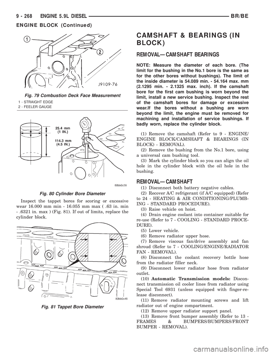
Inspect the tappet bores for scoring or excessive
wear 16.000 mm min - 16.055 mm max ( .63 in. min
- .6321 in. max ) (Fig. 81). If out of limits, replace the
cylinder block.
CAMSHAFT & BEARINGS (IN
BLOCK)
REMOVALÐCAMSHAFT BEARINGS
NOTE: Measure the diameter of each bore. (The
limit for the bushing in the No.1 bore is the same as
for the other bores without bushings). The limit of
the inside diameter is 54.089 min. - 54.164 max. mm
(2.1295 min. - 2.1325 max. inch). If the camshaft
bore for the first cam bushing is worn beyond the
limit, install a new service bushing. Inspect the rest
of the camshaft bores for damage or excessive
wear.If the bores without a bushing are worn
beyond the limit, the engine must be removed for
machining and installation of service bushings. If
badly worn, replace the cylinder block.
(1) Remove the camshaft (Refer to 9 - ENGINE/
ENGINE BLOCK/CAMSHAFT & BEARINGS (IN
BLOCK) - REMOVAL).
(2) Remove the bushing from the No.1 bore, using
a universal cam bushing tool.
(3) Mark the cylinder block so you can align the oil
hole in the cylinder block with the oil hole in the
bushing.
REMOVALÐCAMSHAFT
(1) Disconnect both battery negative cables.
(2) Recover A/C refrigerant (if A/C equipped) (Refer
to 24 - HEATING & AIR CONDITIONING/PLUMB-
ING - STANDARD PROCEDURE).
(3) Raise vehicle on hoist.
(4) Drain engine coolant into container suitable for
re-use (Refer to 7 - COOLING - STANDARD PROCE-
DURE).
(5) Lower vehicle.
(6) Remove radiator upper hose.
(7) Remove viscous fan/drive assembly and fan
shroud (Refer to 7 - COOLING/ENGINE/RADIATOR
FAN - REMOVAL).
(8) Disconnect the coolant recovery bottle hose
from the radiator filler neck.
(9) Disconnect lower radiator hose from radiator
outlet.
(10)Automatic Transmission models:Discon-
nect transmission oil cooler lines from radiator using
Special Tool 6931 (unless equipped with finger-re-
lease disconnect).
(11) Remove radiator mounting screws and lift
radiator out of engine compartment.
(12) Remove upper radiator support panel.
(13) Remove front bumper assembly (Refer to 13 -
FRAMES & BUMPERS/BUMPERS/FRONT
BUMPER - REMOVAL).
Fig. 79 Combustion Deck Face Measurement
1 - STRAIGHT EDGE
2 - FEELER GAUGE
Fig. 80 Cylinder Bore Diameter
Fig. 81 Tappet Bore Diameter
9 - 268 ENGINE 5.9L DIESELBR/BE
ENGINE BLOCK (Continued)
Page 1426 of 2889
(3) Remove the oil pan drain plug and drain the
engine oil. Re-install plug and torque to 60 N´m (44
ft. lbs.) torque.
(4) Remove transmission and transfer case (if
equipped) from vehicle.
(5) Remove flywheel or torque converter drive
plate.
(6) Disconnect starter cables from starter motor.
(7) Remove starter motor (Refer to 8 - ELECTRI-
CAL/STARTING/STARTER MOTOR - REMOVAL)
and transmission adapter plate assembly.
(8) Disconnect cables from starter motor.
(9) Remove the eight flywheel housing to block
bolts and remove housing and starter motor as an
assembly.
(10) Remove oil pan bolts, break the pan to block
seal, and lower pan slightly and remove oil suction
tube fasteners.
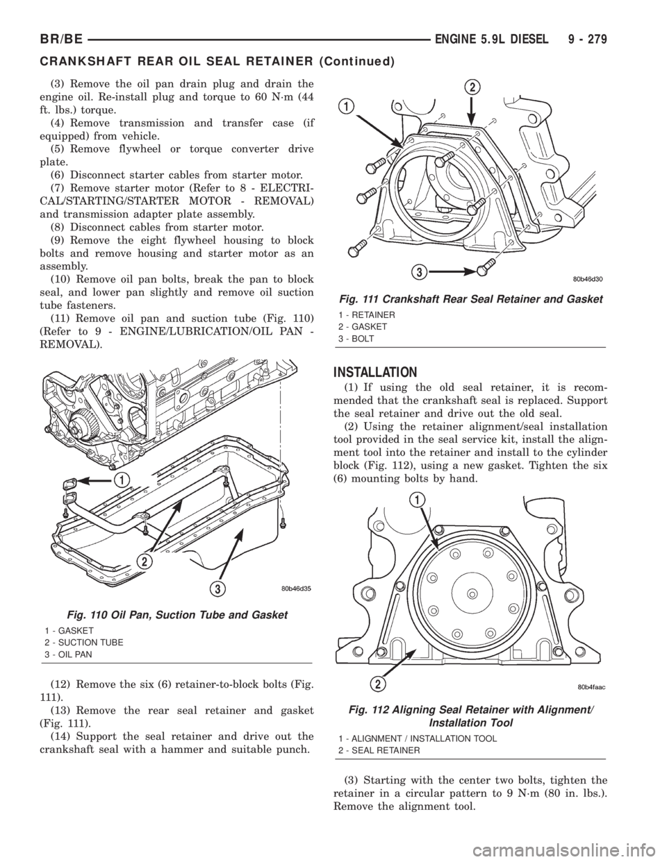
(11) Remove oil pan and suction tube (Fig. 110)
(Refer to 9 - ENGINE/LUBRICATION/OIL PAN -
REMOVAL).
(12) Remove the six (6) retainer-to-block bolts (Fig.
111).
(13) Remove the rear seal retainer and gasket
(Fig. 111).
(14) Support the seal retainer and drive out the
crankshaft seal with a hammer and suitable punch.
INSTALLATION
(1) If using the old seal retainer, it is recom-
mended that the crankshaft seal is replaced. Support
the seal retainer and drive out the old seal.
(2) Using the retainer alignment/seal installation
tool provided in the seal service kit, install the align-
ment tool into the retainer and install to the cylinder
block (Fig. 112), using a new gasket. Tighten the six
(6) mounting bolts by hand.
(3) Starting with the center two bolts, tighten the
retainer in a circular pattern to 9 N´m (80 in. lbs.).
Remove the alignment tool.
Fig. 110 Oil Pan, Suction Tube and Gasket
1 - GASKET
2 - SUCTION TUBE
3 - OIL PAN
Fig. 111 Crankshaft Rear Seal Retainer and Gasket
1 - RETAINER
2 - GASKET
3 - BOLT
Fig. 112 Aligning Seal Retainer with Alignment/
Installation Tool
1 - ALIGNMENT / INSTALLATION TOOL
2 - SEAL RETAINER
BR/BEENGINE 5.9L DIESEL 9 - 279
CRANKSHAFT REAR OIL SEAL RETAINER (Continued)
Page 1442 of 2889
DIAGNOSIS AND TESTINGÐENGINE OIL
PRESSURE
(1) Remove the engine oil pressure sensor and
install Oil Pressure Line and Gauge Tool C-3292 with
a suitable adapter.
(2) Start engine and warm to operating tempera-
ture.
(3) Record engine oil pressure and compare with
engine oil pressure chart.
CAUTION: If engine oil pressure is zero at idle, DO
NOT RUN THE ENGINE.
Engine Oil Pressure (MIN)
At Idle 103.4 kPa (15 psi)
At 2000 rpm 310.2 kPa (45 psi)
If minimum engine oil pressure is below these
ranges, (Refer to 9 - ENGINE - DIAGNOSIS AND
TESTING).
(4) Remove oil pressure gauge and install the oil
pressure sensor. Tighten the sensor to 16 N´m (144
in. lbs.) torque.
OIL
STANDARD PROCEDURE-ENGINE OIL LEVEL
CAUTION: Do not overfill crankcase with engine oil,
oil foaming and oil pressure loss can result.
To ensure proper lubrication of an engine, the
engine oil must be maintained at an acceptable level.
The acceptable oil level is in the SAFE RANGE on
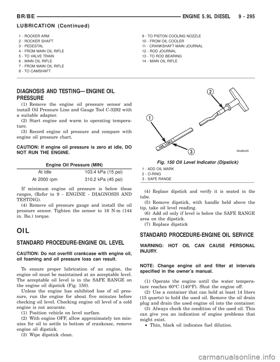
the engine oil dipstick (Fig. 150).
Unless the engine has exhibited loss of oil pres-
sure, run the engine for about five minutes before
checking oil level. Checking engine oil level of a cold
engine is not accurate.
(1) Position vehicle on level surface.
(2) With engine OFF, allow approximately ten min-
utes for oil to settle to bottom of crankcase, remove
engine oil dipstick.
(3) Wipe dipstick clean.(4)
Replace dipstick and verify it is seated in the
tube.
(5) Remove dipstick, with handle held above the
tip, take oil level reading.
(6) Add oil only if level is below the SAFE RANGE
area on the dipstick.
(7) Replace dipstick
STANDARD PROCEDURE-ENGINE OIL SERVICE
WARNING: HOT OIL CAN CAUSE PERSONAL
INJURY.
NOTE: Change engine oil and filter at intervals
specified in the owner's manual.
(1) Operate the engine until the water tempera-
ture reaches 60ÉC (140ÉF). Shut the engine off.
(2) Use a container that can hold at least 14 liters
(15 quarts) to hold the used oil. Remove the oil drain
plug and drain the used engine oil into the container.
(3) Always check the condition of the used oil. This
can give you an indication of engine problems that
might exist.
²Thin, black oil indicates fuel dilution.
1 - ROCKER ARM
2 - ROCKER SHAFT
3 - PEDESTAL
4 - FROM MAIN OIL RIFLE
5 - TO VALVE TRAIN
6 - MAIN OIL RIFLE
7 - FROM MAIN OIL RIFLE
8 - TO CAMSHAFT9 - TO PISTON COOLING NOZZLE
10 - FROM OIL COOLER
11 - CRANKSHAFT MAIN JOURNAL
12 - ROD JOURNAL
13 - TO ROD BEARING
14 - MAIN OIL RIFLE
Fig. 150 Oil Level Indicator (Dipstick)
1 - ADD OIL MARK
2 - O-RING
3 - SAFE RANGE
BR/BEENGINE 5.9L DIESEL 9 - 295
LUBRICATION (Continued)
Page 1453 of 2889
(3) Install the injection pump (Refer to 14 - FUEL
SYSTEM/FUEL DELIVERY/FUEL INJECTION
PUMP - INSTALLATION).
(4) Install the camshaft (Refer to 9 - ENGINE/EN-
GINE BLOCK/CAMSHAFT & BEARINGS (IN
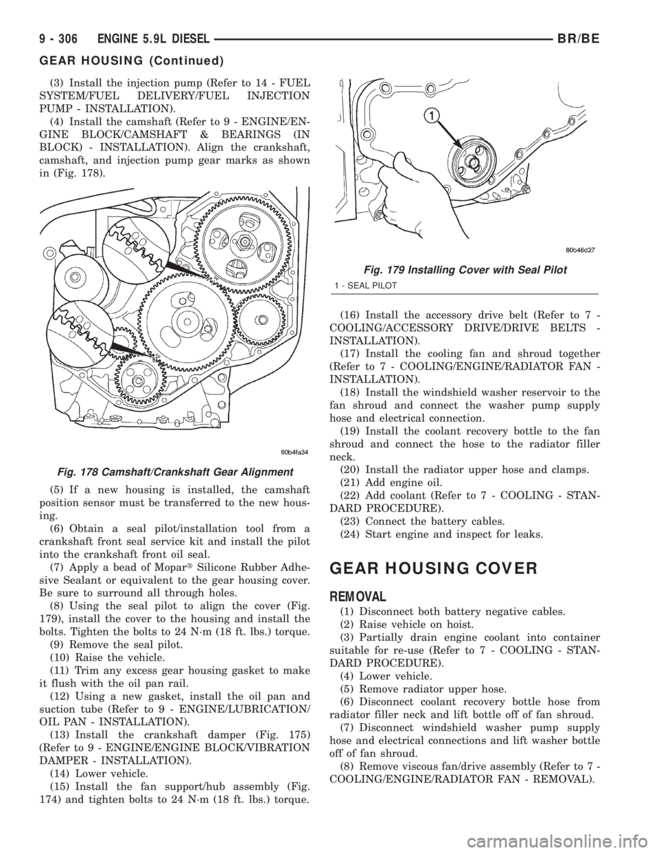
BLOCK) - INSTALLATION). Align the crankshaft,
camshaft, and injection pump gear marks as shown
in (Fig. 178).
(5) If a new housing is installed, the camshaft
position sensor must be transferred to the new hous-
ing.
(6) Obtain a seal pilot/installation tool from a
crankshaft front seal service kit and install the pilot
into the crankshaft front oil seal.
(7) Apply a bead of MopartSilicone Rubber Adhe-
sive Sealant or equivalent to the gear housing cover.
Be sure to surround all through holes.
(8) Using the seal pilot to align the cover (Fig.
179), install the cover to the housing and install the
bolts. Tighten the bolts to 24 N´m (18 ft. lbs.) torque.
(9) Remove the seal pilot.
(10) Raise the vehicle.
(11) Trim any excess gear housing gasket to make
it flush with the oil pan rail.
(12) Using a new gasket, install the oil pan and
suction tube (Refer to 9 - ENGINE/LUBRICATION/
OIL PAN - INSTALLATION).
(13) Install the crankshaft damper (Fig. 175)
(Refer to 9 - ENGINE/ENGINE BLOCK/VIBRATION
DAMPER - INSTALLATION).
(14) Lower vehicle.
(15) Install the fan support/hub assembly (Fig.
174) and tighten bolts to 24 N´m (18 ft. lbs.) torque.(16) Install the accessory drive belt (Refer to 7 -
COOLING/ACCESSORY DRIVE/DRIVE BELTS -
INSTALLATION).
(17) Install the cooling fan and shroud together
(Refer to 7 - COOLING/ENGINE/RADIATOR FAN -
INSTALLATION).
(18) Install the windshield washer reservoir to the
fan shroud and connect the washer pump supply
hose and electrical connection.
(19) Install the coolant recovery bottle to the fan
shroud and connect the hose to the radiator filler
neck.
(20) Install the radiator upper hose and clamps.
(21) Add engine oil.
(22) Add coolant (Refer to 7 - COOLING - STAN-
DARD PROCEDURE).
(23) Connect the battery cables.
(24) Start engine and inspect for leaks.
GEAR HOUSING COVER
REMOVAL
(1) Disconnect both battery negative cables.
(2) Raise vehicle on hoist.
(3) Partially drain engine coolant into container
suitable for re-use (Refer to 7 - COOLING - STAN-
DARD PROCEDURE).
(4) Lower vehicle.
(5) Remove radiator upper hose.
(6) Disconnect coolant recovery bottle hose from
radiator filler neck and lift bottle off of fan shroud.
(7) Disconnect windshield washer pump supply
hose and electrical connections and lift washer bottle
off of fan shroud.
(8) Remove viscous fan/drive assembly (Refer to 7 -
COOLING/ENGINE/RADIATOR FAN - REMOVAL).
Fig. 178 Camshaft/Crankshaft Gear Alignment
Fig. 179 Installing Cover with Seal Pilot
1 - SEAL PILOT
9 - 306 ENGINE 5.9L DIESELBR/BE
GEAR HOUSING (Continued)
Page 1454 of 2889
(9) Remove the accessory drive belt (Refer to 7 -
COOLING/ACCESSORY DRIVE/DRIVE BELTS -
REMOVAL).
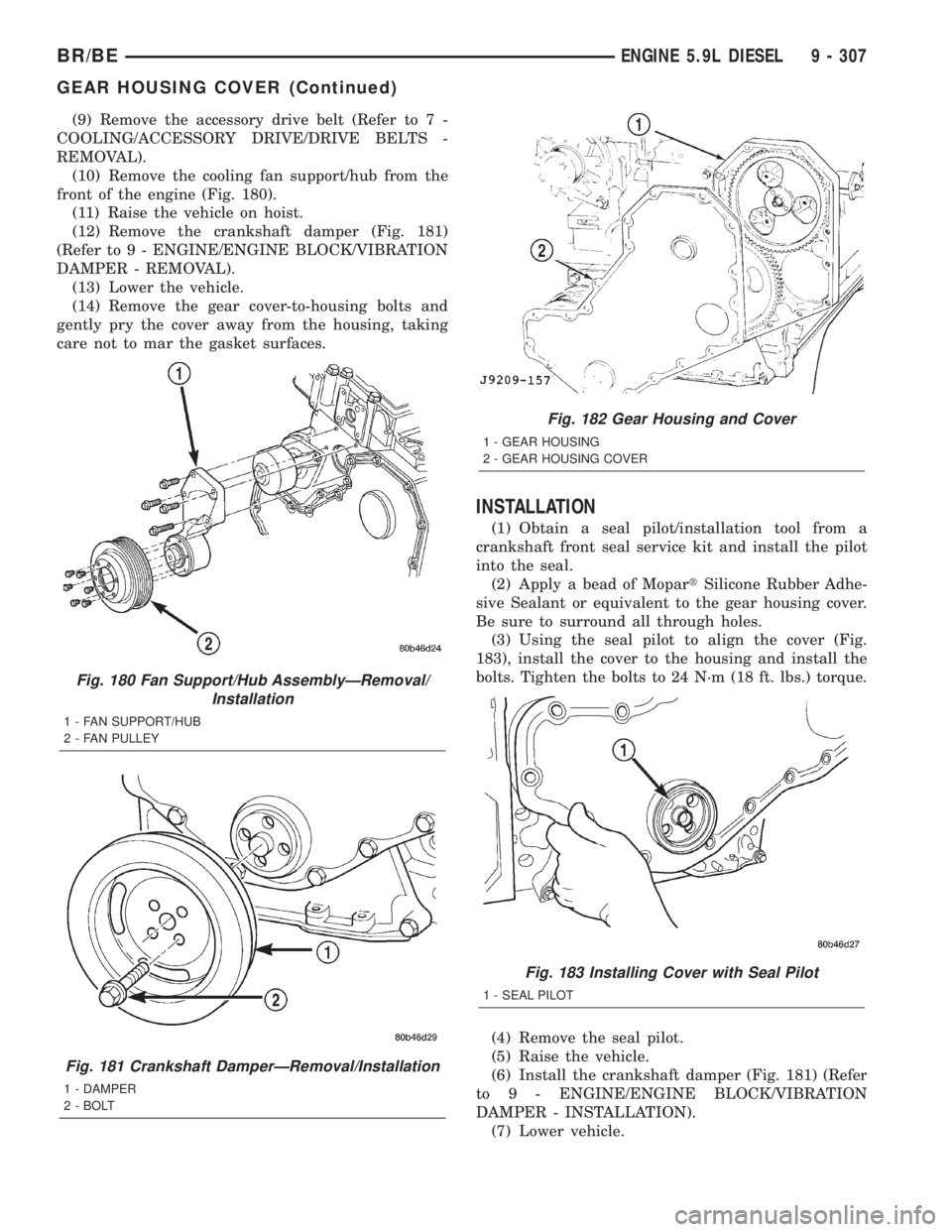
(10) Remove the cooling fan support/hub from the
front of the engine (Fig. 180).
(11) Raise the vehicle on hoist.
(12) Remove the crankshaft damper (Fig. 181)
(Refer to 9 - ENGINE/ENGINE BLOCK/VIBRATION
DAMPER - REMOVAL).
(13) Lower the vehicle.
(14) Remove the gear cover-to-housing bolts and
gently pry the cover away from the housing, taking
care not to mar the gasket surfaces.
INSTALLATION
(1) Obtain a seal pilot/installation tool from a
crankshaft front seal service kit and install the pilot
into the seal.
(2) Apply a bead of MopartSilicone Rubber Adhe-
sive Sealant or equivalent to the gear housing cover.
Be sure to surround all through holes.
(3) Using the seal pilot to align the cover (Fig.
183), install the cover to the housing and install the
bolts. Tighten the bolts to 24 N´m (18 ft. lbs.) torque.
(4) Remove the seal pilot.
(5) Raise the vehicle.
(6) Install the crankshaft damper (Fig. 181) (Refer
to 9 - ENGINE/ENGINE BLOCK/VIBRATION
DAMPER - INSTALLATION).
(7) Lower vehicle.
Fig. 180 Fan Support/Hub AssemblyÐRemoval/
Installation
1 - FAN SUPPORT/HUB
2 - FAN PULLEY
Fig. 181 Crankshaft DamperÐRemoval/Installation
1 - DAMPER
2 - BOLT
Fig. 182 Gear Housing and Cover
1 - GEAR HOUSING
2 - GEAR HOUSING COVER
Fig. 183 Installing Cover with Seal Pilot
1 - SEAL PILOT
BR/BEENGINE 5.9L DIESEL 9 - 307
GEAR HOUSING COVER (Continued)
Page 1471 of 2889
CAUTION: The turbocharger is only serviced as an
assembly. Do not attempt to repair the turbocharger
as turbocharger and/or engine damage can result.
CLEANING
Clean the turbocharger and exhaust manifold
mounting surfaces with a suitable scraper.
INSPECTION
Visually inspect the turbocharger and exhaust
manifold gasket surfaces. Replace stripped or eroded
mounting studs.
(1) Visually inspect the turbocharger for cracks.
The following cracks are NOT acceptable:
²Cracks in the turbine and compressor housing
that go completely through.
²Cracks in the mounting flange that are longer
than 15 mm (0.6 in.).
²Cracks in the mounting flange that intersect
bolt through-holes.
²Two (2) Cracks in the mounting flange that are
closer than 6.4 mm (0.25 in.) together.
(2) Visually inspect the impeller and compressor
wheel fins for nicks, cracks, or chips. Note: Some
impellers may have a factory placed paint mark
which, after normal operation, appears to be a crack.Remove this mark with a suitable solvent to verify
that it is not a crack.
(3) Visually inspect the turbocharger compressor
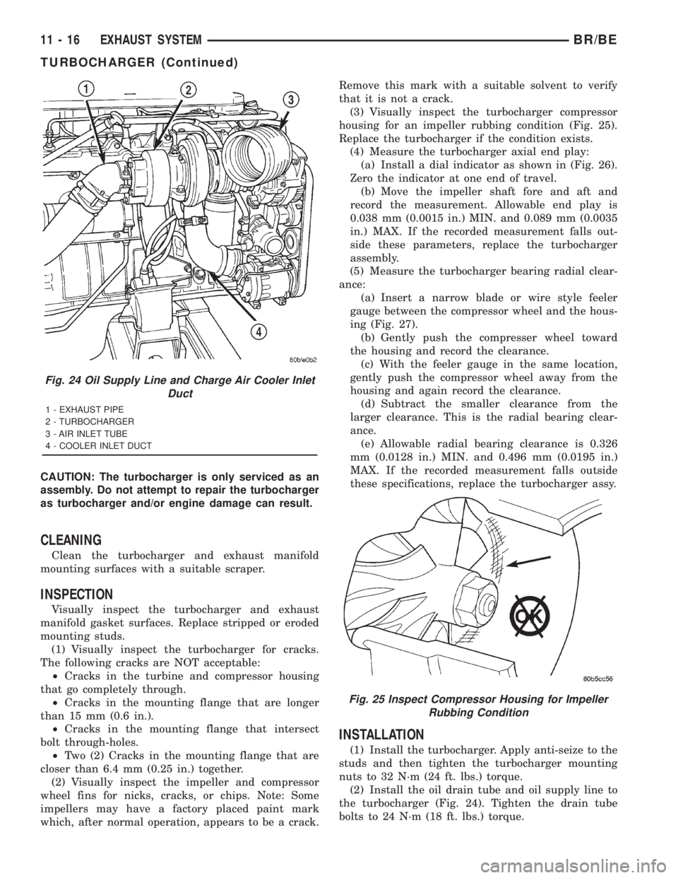
housing for an impeller rubbing condition (Fig. 25).
Replace the turbocharger if the condition exists.
(4) Measure the turbocharger axial end play:
(a) Install a dial indicator as shown in (Fig. 26).
Zero the indicator at one end of travel.
(b) Move the impeller shaft fore and aft and
record the measurement. Allowable end play is
0.038 mm (0.0015 in.) MIN. and 0.089 mm (0.0035
in.) MAX. If the recorded measurement falls out-
side these parameters, replace the turbocharger
assembly.
(5) Measure the turbocharger bearing radial clear-
ance:
(a) Insert a narrow blade or wire style feeler
gauge between the compressor wheel and the hous-
ing (Fig. 27).
(b) Gently push the compresser wheel toward
the housing and record the clearance.
(c) With the feeler gauge in the same location,
gently push the compressor wheel away from the
housing and again record the clearance.
(d) Subtract the smaller clearance from the
larger clearance. This is the radial bearing clear-
ance.
(e) Allowable radial bearing clearance is 0.326
mm (0.0128 in.) MIN. and 0.496 mm (0.0195 in.)
MAX. If the recorded measurement falls outside
these specifications, replace the turbocharger assy.
INSTALLATION
(1) Install the turbocharger. Apply anti-seize to the
studs and then tighten the turbocharger mounting
nuts to 32 N´m (24 ft. lbs.) torque.
(2) Install the oil drain tube and oil supply line to
the turbocharger (Fig. 24). Tighten the drain tube
bolts to 24 N´m (18 ft. lbs.) torque.
Fig. 24 Oil Supply Line and Charge Air Cooler Inlet
Duct
1 - EXHAUST PIPE
2 - TURBOCHARGER
3 - AIR INLET TUBE
4 - COOLER INLET DUCT
Fig. 25 Inspect Compressor Housing for Impeller
Rubbing Condition
11 - 16 EXHAUST SYSTEMBR/BE
TURBOCHARGER (Continued)
Page 1473 of 2889
(3) Remove the front support bracket.
(4) Discharge the A/C system (Refer to 24 - HEAT-
ING & AIR CONDITIONING/PLUMBING - STAN-
DARD PROCEDURE) and remove the A/C condenser
(Refer to 24 - HEATING & AIR CONDITIONING/
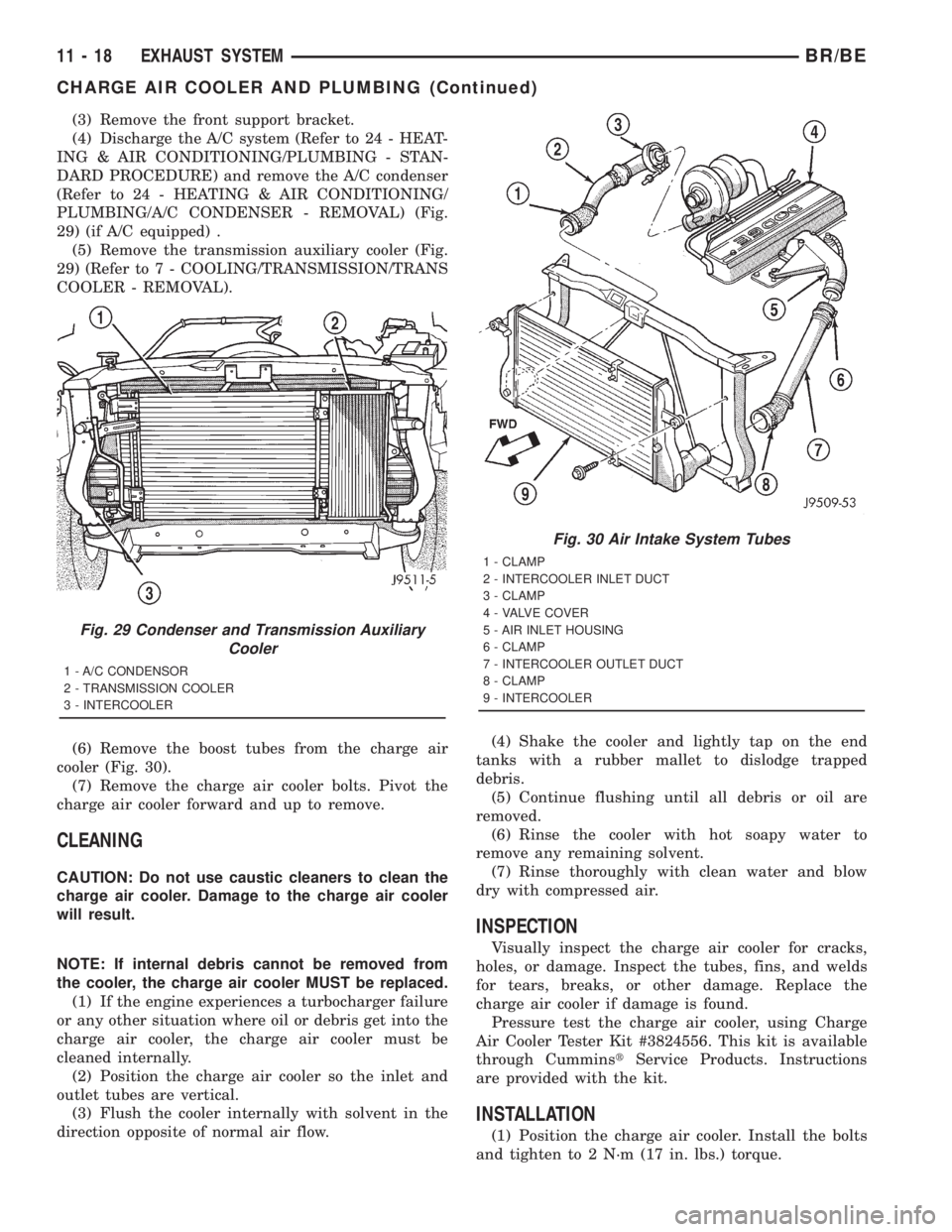
PLUMBING/A/C CONDENSER - REMOVAL) (Fig.
29) (if A/C equipped) .
(5) Remove the transmission auxiliary cooler (Fig.
29) (Refer to 7 - COOLING/TRANSMISSION/TRANS
COOLER - REMOVAL).
(6) Remove the boost tubes from the charge air
cooler (Fig. 30).
(7) Remove the charge air cooler bolts. Pivot the
charge air cooler forward and up to remove.
CLEANING
CAUTION: Do not use caustic cleaners to clean the
charge air cooler. Damage to the charge air cooler
will result.
NOTE: If internal debris cannot be removed from
the cooler, the charge air cooler MUST be replaced.
(1) If the engine experiences a turbocharger failure
or any other situation where oil or debris get into the
charge air cooler, the charge air cooler must be
cleaned internally.
(2) Position the charge air cooler so the inlet and
outlet tubes are vertical.
(3) Flush the cooler internally with solvent in the
direction opposite of normal air flow.(4) Shake the cooler and lightly tap on the end
tanks with a rubber mallet to dislodge trapped
debris.
(5) Continue flushing until all debris or oil are
removed.
(6) Rinse the cooler with hot soapy water to
remove any remaining solvent.
(7) Rinse thoroughly with clean water and blow
dry with compressed air.
INSPECTION
Visually inspect the charge air cooler for cracks,
holes, or damage. Inspect the tubes, fins, and welds
for tears, breaks, or other damage. Replace the
charge air cooler if damage is found.
Pressure test the charge air cooler, using Charge
Air Cooler Tester Kit #3824556. This kit is available
through CumminstService Products. Instructions
are provided with the kit.
INSTALLATION
(1) Position the charge air cooler. Install the bolts
and tighten to 2 N´m (17 in. lbs.) torque.
Fig. 29 Condenser and Transmission Auxiliary
Cooler
1 - A/C CONDENSOR
2 - TRANSMISSION COOLER
3 - INTERCOOLER
Fig. 30 Air Intake System Tubes
1 - CLAMP
2 - INTERCOOLER INLET DUCT
3 - CLAMP
4 - VALVE COVER
5 - AIR INLET HOUSING
6 - CLAMP
7 - INTERCOOLER OUTLET DUCT
8 - CLAMP
9 - INTERCOOLER
11 - 18 EXHAUST SYSTEMBR/BE
CHARGE AIR COOLER AND PLUMBING (Continued)
Page 1481 of 2889
FRAME
DESCRIPTION
The BR/BE frame is the structural center of the
vehicle. In addition to supporting the body and pay-
load, the frame provides a station for the engine and
drivetrain. BR/BE trucks have a ladder type frame
with Box-section front rails, dropped center section,
and open-channel side rails in the rear.
Cross members attach to the side rails with rivets,
welds, or bolts. The cab is isolated from the frame
with rubber load cushions with through bolts. The
cargo box or bed is attached to the frame with bolts.
The frame is designed to absorb and dissipate flex-
ing and twisting due to acceleration, braking, corner-
ing, and road surface variances without bending
when subjected to normal driving conditions.
FRAME SERVICE
SAFETY PRECAUTIONS AND WARNINGS
WARNING: USE EYE PROTECTION WHEN GRIND-
ING OR WELDING METAL, SERIOUS EYE INJURY
CAN RESULT. BEFORE PROCEEDING WITH FRAME
REPAIR INVOLVING GRINDING OR WELDING, VER-
IFY THAT VEHICLE FUEL SYSTEM IS NOT LEAKING
OR IN CONTACT WITH REPAIR AREA, PERSONAL
INJURY CAN RESULT. DO NOT ALLOW OPEN
FLAME TO CONTACT PLASTIC BODY PANELS.
FIRE OR EXPLOSION CAN RESULT. WHEN
WELDED FRAME COMPONENTS ARE REPLACED,
100% PENETRATION WELD MUST BE ACHIEVED
DURING INSTALLATION. IF NOT, DANGEROUS
OPERATING CONDITIONS CAN RESULT. STAND
CLEAR OF CABLES OR CHAINS ON PULLING
EQUIPMENT DURING FRAME STRAIGHTENING
OPERATIONS, PERSONAL INJURY CAN RESULT.
DO NOT VENTURE UNDER A HOISTED VEHICLE
THAT IS NOT SUPPORTED ON SAFETY STANDS,
PERSONAL INJURY CAN RESULT.
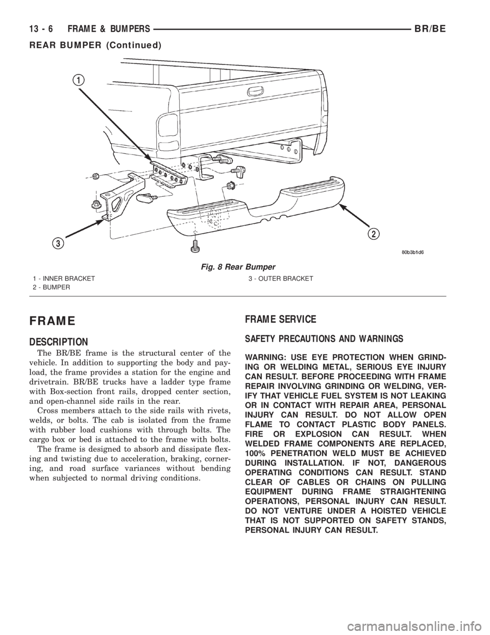
Fig. 8 Rear Bumper
1 - INNER BRACKET
2 - BUMPER3 - OUTER BRACKET
13 - 6 FRAME & BUMPERSBR/BE
REAR BUMPER (Continued)