2001 DODGE RAM service
[x] Cancel search: servicePage 1377 of 2889
LUBRICATION
DESCRIPTION..........................292
OPERATION............................292
DIAGNOSIS AND TESTING................295
ENGINE OIL PRESSURE................295
OIL
STANDARD PROCEDURE.................295
ENGINE OIL LEVEL....................295
ENGINE OIL SERVICE..................295
OIL COOLER & LINES
CLEANING.............................296
OIL FILTER
REMOVAL.............................296
INSTALLATION..........................296
OIL PAN
REMOVAL.............................296
CLEANING.............................297
INSPECTION...........................297
INSTALLATION..........................297
OIL PRESSURE RELIEF VALVE
REMOVAL.............................297
CLEANING.............................297
INSPECTION...........................297
INSTALLATION..........................298
OIL PRESSURE SENSOR/SWITCH
DESCRIPTION..........................298OPERATION............................298
REMOVAL.............................298
INSTALLATION..........................299
OIL PUMP
REMOVAL.............................299
CLEANING.............................299
INSPECTION...........................299
INSTALLATION..........................300
INTAKE MANIFOLD
REMOVAL.............................301
CLEANING.............................302
INSPECTION...........................302
INSTALLATION..........................302
EXHAUST MANIFOLD
REMOVAL.............................303
CLEANING.............................304
INSPECTION...........................304
INSTALLATION..........................304
GEAR HOUSING
REMOVAL.............................304
INSTALLATION..........................305
GEAR HOUSING COVER
REMOVAL.............................306
INSTALLATION..........................307
9 - 230 ENGINE 5.9L DIESELBR/BE
Page 1378 of 2889
ENGINE 5.9L DIESEL
DESCRIPTION
The cylinder block is constructed of cast iron. The
casting is a skirted design which incorporates longi-
tudal ribs for superior strength and noise reduction.
The block incorporates metric straight thread o-ring
fittings at lubrication oil access points. The engine is
manufactured with the cylinders being a non-sleeved
type cylinder. However, one approved service method
is to bore out the cylinders and add cylinder sleeves
to the cylinder block.
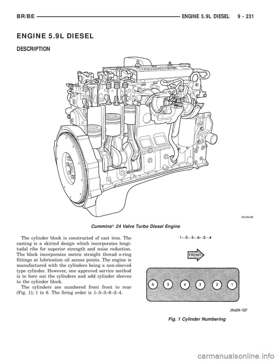
The cylinders are numbered front front to rear
(Fig. 1); 1 to 6. The firing order is 1±5±3±6±2±4.
CumminsT24 Valve Turbo Diesel Engine
Fig. 1 Cylinder Numbering
BR/BEENGINE 5.9L DIESEL 9 - 231
Page 1383 of 2889
EXCESSIVE WHITE SMOKE
POSSIBLE CAUSE CORRECTION
Fuel injector protrusion not correct. Check washer (shim) at bottom of fuel injector for
correct thickness. (Refer to 14 - FUEL SYSTEM/FUEL
INJECTION/FUEL INJECTOR - INSTALLATION)
Fuel injection pump malfunctioning. A DTC should have been set. Refer to Powertrain
Diagnostic Procedures Information.
Fuel supply side restriction to transfer pump. Refer to Fuel Transfer Pump Pressure (Refer to 14 -
FUEL SYSTEM/FUEL DELIVERY/FUEL TRANSFER
PUMP - DIAGNOSIS AND TESTING)
Fuel transfer (lift) pump malfunctioning. A DTC should have been set. Refer to Powertrain
Diagnostic Procedures Information. Also refer to Fuel
Transfer Pump Pressure Testing (Refer to 14 - FUEL
SYSTEM/FUEL DELIVERY/FUEL TRANSFER PUMP -
DIAGNOSIS AND TESTING).
Intake/Exhaust valve adjustments not correct (too tight). (Refer to 9 - ENGINE/CYLINDER HEAD/INTAKE/
EXHAUST VALVES & SEATS - STANDARD
PROCEDURE).
Intake manifold air temperature sensor malfunctioning. A DTC should have been set. Refer to Powertrain
Diagnostic Procedures Information.
Intake manifold heater circuit not functioning correctly in
cold weather.A DTC should have been set. Refer to Powertrain
Diagnostic Procedures Information. Also check heater
elements for correct operation.
Intake manifold heater elements not functioning
correctly in cold weather.A diagnostic trouble code WILL NOT BE SET if heater
elements are malfunctioning. Refer to NTC tests in
Powertrain Diagnostic Procedures Information.
Internal engine damage (scuffed cylinder). Analyze engine oil and inspect oil filter to locate area of
probable damage.
Restriction in fuel supply side of fuel system. Refer to Fuel Transfer Pump Pressure Testing (Refer to
14 - FUEL SYSTEM/FUEL DELIVERY/FUEL
TRANSFER PUMP - DIAGNOSIS AND TESTING).
Static timing incorrect. A DTC should have been set. If so, (Refer to 14 -
FUEL SYSTEM/FUEL DELIVERY/FUEL INJECTION
PUMP - DIAGNOSIS AND TESTING).
EXCESSIVE BLUE SMOKE
POSSIBLE CAUSE CORRECTION
Dirty air cleaner or restricted turbocharger intake duct. Check Filter MinderTat air filter housing. (Refer to 9 -
ENGINE/AIR INTAKE SYSTEM/AIR CLEANER
ELEMENT - REMOVAL).
Air leak in boost system between turbocharger
compressor outlet and intake manifold.Service air charge system..
Obstruction in exhaust manifold. Remove exhaust manifold and inspect for blockage
(Refer to 9 - ENGINE/MANIFOLDS/EXHAUST
MANIFOLD - REMOVAL).
Restricted turbocharger drain tube. Remove turbocharger drain tube and remove
obstruction.
Crankcase ventilation system plugged. Inspect crankcase breather and vent tube for sludge
formation or obstructions.
9 - 236 ENGINE 5.9L DIESELBR/BE
ENGINE 5.9L DIESEL (Continued)
Page 1388 of 2889
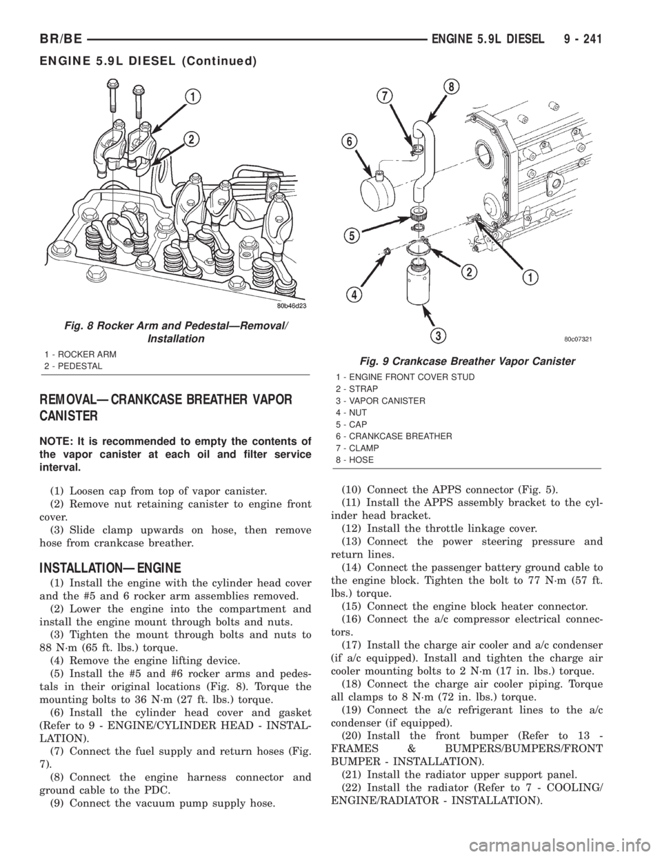
REMOVALÐCRANKCASE BREATHER VAPOR
CANISTER
NOTE: It is recommended to empty the contents of
the vapor canister at each oil and filter service
interval.
(1) Loosen cap from top of vapor canister.
(2) Remove nut retaining canister to engine front
cover.
(3) Slide clamp upwards on hose, then remove
hose from crankcase breather.
INSTALLATIONÐENGINE
(1) Install the engine with the cylinder head cover
and the #5 and 6 rocker arm assemblies removed.
(2) Lower the engine into the compartment and
install the engine mount through bolts and nuts.
(3) Tighten the mount through bolts and nuts to
88 N´m (65 ft. lbs.) torque.
(4) Remove the engine lifting device.
(5) Install the #5 and #6 rocker arms and pedes-
tals in their original locations (Fig. 8). Torque the
mounting bolts to 36 N´m (27 ft. lbs.) torque.
(6) Install the cylinder head cover and gasket
(Refer to 9 - ENGINE/CYLINDER HEAD - INSTAL-
LATION).
(7) Connect the fuel supply and return hoses (Fig.
7).
(8) Connect the engine harness connector and
ground cable to the PDC.
(9) Connect the vacuum pump supply hose.(10) Connect the APPS connector (Fig. 5).
(11) Install the APPS assembly bracket to the cyl-
inder head bracket.
(12) Install the throttle linkage cover.
(13) Connect the power steering pressure and
return lines.
(14) Connect the passenger battery ground cable to
the engine block. Tighten the bolt to 77 N´m (57 ft.
lbs.) torque.
(15) Connect the engine block heater connector.
(16) Connect the a/c compressor electrical connec-
tors.
(17) Install the charge air cooler and a/c condenser
(if a/c equipped). Install and tighten the charge air
cooler mounting bolts to 2 N´m (17 in. lbs.) torque.
(18) Connect the charge air cooler piping. Torque
all clamps to 8 N´m (72 in. lbs.) torque.
(19) Connect the a/c refrigerant lines to the a/c
condenser (if equipped).
(20) Install the front bumper (Refer to 13 -
FRAMES & BUMPERS/BUMPERS/FRONT
BUMPER - INSTALLATION).
(21) Install the radiator upper support panel.
(22) Install the radiator (Refer to 7 - COOLING/
ENGINE/RADIATOR - INSTALLATION).
Fig. 8 Rocker Arm and PedestalÐRemoval/
Installation
1 - ROCKER ARM
2 - PEDESTALFig. 9 Crankcase Breather Vapor Canister
1 - ENGINE FRONT COVER STUD
2 - STRAP
3 - VAPOR CANISTER
4 - NUT
5 - CAP
6 - CRANKCASE BREATHER
7 - CLAMP
8 - HOSE
BR/BEENGINE 5.9L DIESEL 9 - 241
ENGINE 5.9L DIESEL (Continued)
Page 1400 of 2889
CYLINDER HEAD COVER(S)
REMOVAL
(1) Disconnect both battery negative cables.
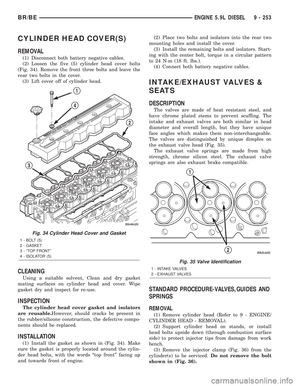
(2) Loosen the five (5) cylinder head cover bolts
(Fig. 34). Remove the front three bolts and leave the
rear two bolts in the cover.
(3) Lift cover off of cylinder head.
CLEANING
Using a suitable solvent, Clean and dry gasket
mating surfaces on cylinder head and cover. Wipe
gasket dry and inspect for re-use.
INSPECTION
The cylinder head cover gasket and isolators
are reusable.However, should cracks be present in
the rubber/silicone construction, the defective compo-
nents should be replaced.
INSTALLATION
(1) Install the gasket as shown in (Fig. 34). Make
sure the gasket is properly located around the cylin-
der head bolts, with the words ªtop frontº facing up
and towards front of engine.(2) Place two bolts and isolators into the rear two
mounting holes and install the cover.
(3) Install the remaining bolts and isolators. Start-
ing with the center bolt, torque in a circular pattern
to 24 N´m (18 ft. lbs.).
(4) Connect both battery negative cables.
INTAKE/EXHAUST VALVES &
SEATS
DESCRIPTION
The valves are made of heat resistant steel, and
have chrome plated stems to prevent scuffing. The
intake and exhaust valves are both similar in head
diameter and overall length, but they have unique
face angles which makes them non-interchangeable.
The valves are distinguished by unique dimples on
the exhaust valve head (Fig. 35).
The exhaust valve springs are made from high
strength, chrome silicon steel. The exhaust valve
springs are also exhaust brake compatible.
STANDARD PROCEDURE-VALVES,GUIDES AND
SPRINGS
REMOVAL
(1) Remove cylinder head (Refer to 9 - ENGINE/
CYLINDER HEAD - REMOVAL).
(2) Support cylinder head on stands, or install
head bolts upside down (through combustion surface
side) to protect injector tips from damage from work
bench.
(3) Remove the injector clamp (Fig. 36) from the
cylinder(s) to be serviced.Do not remove the bolt
shown in (Fig. 36).
Fig. 34 Cylinder Head Cover and Gasket
1 - BOLT (5)
2 - GASKET
3 - ªTOP FRONTº
4 - ISOLATOR (5)
Fig. 35 Valve Identification
1 - INTAKE VALVES
2 - EXHAUST VALVES
BR/BEENGINE 5.9L DIESEL 9 - 253
Page 1405 of 2889
(6) If adjustment/resetting is required, loosen the
lock nut on rocker arms and turn the adjusting screw
until the desired lash is obtained:
²INTAKE0.254 mm (0.010 in.)
²EXHAUST0.508 mm (0.020 in.)Tighten the lock
nut and re-check the valve lash.
(7) Using the crankshaft barring tool, rotate the
crankshaftone revolution (360É) to align the pump
gear mark to the 6 o'clock position in relation to the
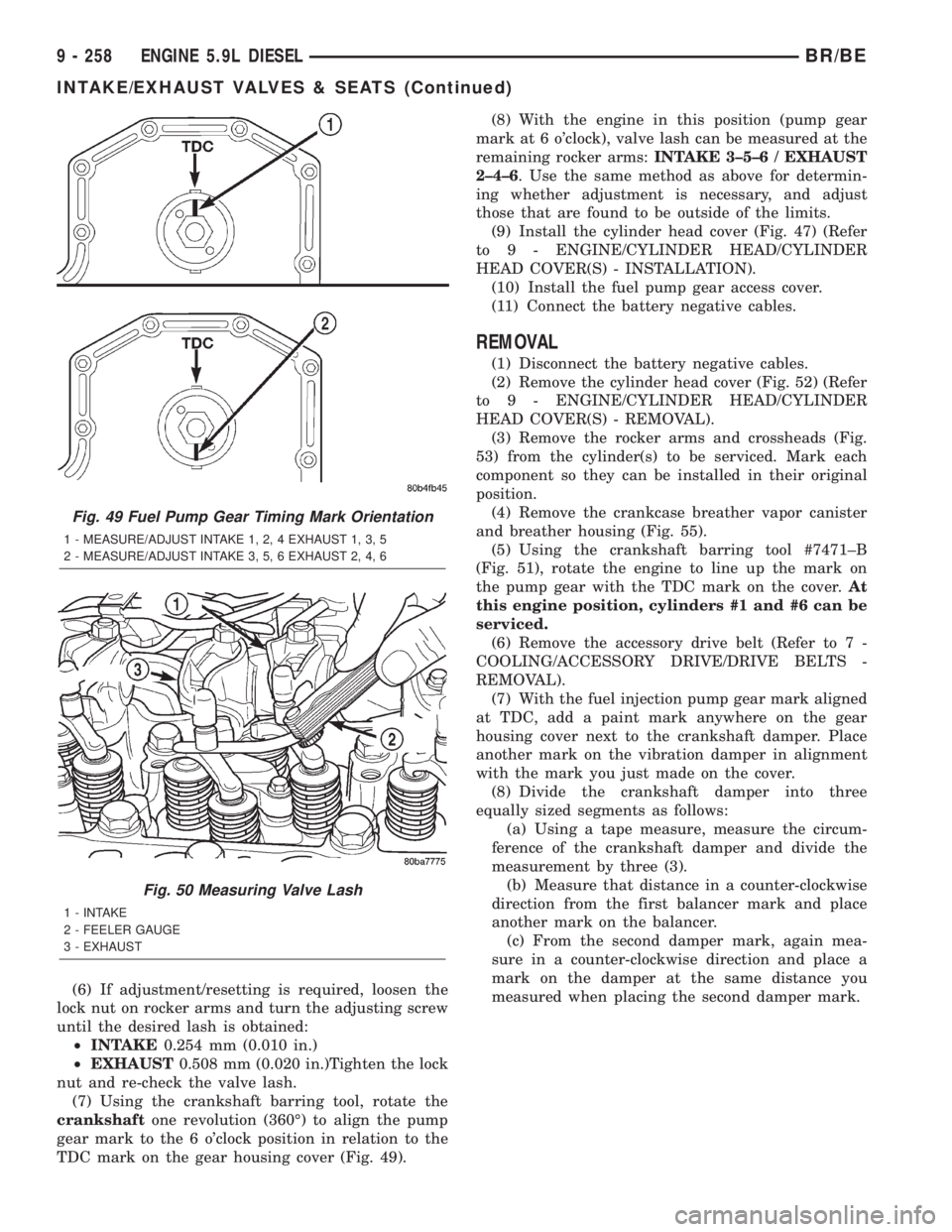
TDC mark on the gear housing cover (Fig. 49).(8) With the engine in this position (pump gear
mark at 6 o'clock), valve lash can be measured at the
remaining rocker arms:INTAKE 3±5±6 / EXHAUST
2±4±6. Use the same method as above for determin-
ing whether adjustment is necessary, and adjust
those that are found to be outside of the limits.
(9) Install the cylinder head cover (Fig. 47) (Refer
to 9 - ENGINE/CYLINDER HEAD/CYLINDER
HEAD COVER(S) - INSTALLATION).
(10) Install the fuel pump gear access cover.
(11) Connect the battery negative cables.
REMOVAL
(1) Disconnect the battery negative cables.
(2) Remove the cylinder head cover (Fig. 52) (Refer
to 9 - ENGINE/CYLINDER HEAD/CYLINDER
HEAD COVER(S) - REMOVAL).
(3) Remove the rocker arms and crossheads (Fig.
53) from the cylinder(s) to be serviced. Mark each
component so they can be installed in their original
position.
(4) Remove the crankcase breather vapor canister
and breather housing (Fig. 55).
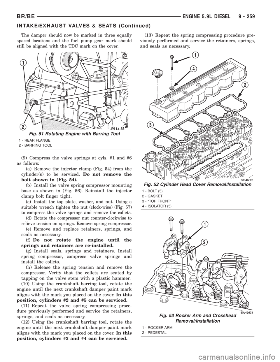
(5) Using the crankshaft barring tool #7471±B
(Fig. 51), rotate the engine to line up the mark on
the pump gear with the TDC mark on the cover.At
this engine position, cylinders #1 and #6 can be
serviced.
(6) Remove the accessory drive belt (Refer to 7 -
COOLING/ACCESSORY DRIVE/DRIVE BELTS -
REMOVAL).
(7) With the fuel injection pump gear mark aligned
at TDC, add a paint mark anywhere on the gear
housing cover next to the crankshaft damper. Place
another mark on the vibration damper in alignment
with the mark you just made on the cover.
(8) Divide the crankshaft damper into three
equally sized segments as follows:
(a) Using a tape measure, measure the circum-
ference of the crankshaft damper and divide the
measurement by three (3).
(b) Measure that distance in a counter-clockwise
direction from the first balancer mark and place
another mark on the balancer.
(c) From the second damper mark, again mea-
sure in a counter-clockwise direction and place a
mark on the damper at the same distance you
measured when placing the second damper mark.
Fig. 49 Fuel Pump Gear Timing Mark Orientation
1 - MEASURE/ADJUST INTAKE 1, 2, 4 EXHAUST 1, 3, 5
2 - MEASURE/ADJUST INTAKE 3, 5, 6 EXHAUST 2, 4, 6
Fig. 50 Measuring Valve Lash
1 - INTAKE
2 - FEELER GAUGE
3 - EXHAUST
9 - 258 ENGINE 5.9L DIESELBR/BE
INTAKE/EXHAUST VALVES & SEATS (Continued)
Page 1406 of 2889
The damper should now be marked in three equally
spaced locations and the fuel pump gear mark should
still be aligned with the TDC mark on the cover.
(9) Compress the valve springs at cyls. #1 and #6
as follows:
(a) Remove the injector clamp (Fig. 54) from the
cylinder(s) to be serviced.Do not remove the
bolt shown in (Fig. 54).
(b) Install the valve spring compressor mounting
base as shown in (Fig. 56). Reinstall the injector
clamp bolt finger tight.
(c)
Install the top plate, washer, and nut. Using a
suitable wrench tighten the nut (clock-wise) (Fig. 57)
to compress the valve springs and remove the collets.
(d)Rotate the compressor nut counter-clockwise to
relieve tension on springs. Remove spring compressor.
(e) Remove and replace retainers, springs, and
seals as necessary.
(f)Do not rotate the engine until the
springs and retainers are re-installed.
(g) Install seals, springs and retainers. Install
spring compressor, compress valve springs and
install the collets.
(h) Release the spring tension and remove the
compressor. Verify that the collets are seated by
tapping on the valve stem with a plastic hammer.
(10) Using the crankshaft barring tool, rotate the
engine until the next crankshaft damper paint mark
aligns with the mark you placed on the cover.In this
position, cylinders #2 and #5 can be serviced.
(11) Repeat the valve spring compressing proce-
dure previously performed and service the retainers,
springs, and seals as necessary.
(12) Using the crankshaft barring tool, rotate the
engine until the next crankshaft damper paint mark
aligns with the mark you placed on the cover.In this
position, cylinders #3 and #4 can be serviced.(13) Repeat the spring compressing procedure pre-
viously performed and service the retainers, springs,
and seals as necessary.
Fig. 51 Rotating Engine with Barring Tool
1 - REAR FLANGE
2 - BARRING TOOL
Fig. 52 Cylinder Head Cover Removal/Installation
1 - BOLT (5)
2 - GASKET
3 - ªTOP FRONTº
4 - ISOLATOR (5)
Fig. 53 Rocker Arm and Crosshead
Removal/Installation
1 - ROCKER ARM
2 - PEDESTAL
BR/BEENGINE 5.9L DIESEL 9 - 259
INTAKE/EXHAUST VALVES & SEATS (Continued)
Page 1408 of 2889
(4)Verify valve lash adjustment (Refer to 9 -
ENGINE/CYLINDER HEAD/INTAKE/EXHAUST
VALVES & SEATS - STANDARD PROCEDURE).
(5) Install cylinder head cover and reusable gasket
(Fig. 52) (Refer to 9 - ENGINE/CYLINDER HEAD/
CYLINDER HEAD COVER(S) - INSTALLATION).
(6) Install the accessory drive belt (Refer to 7 -
COOLING/ACCESSORY DRIVE/DRIVE BELTS -
INSTALLATION).
(7) Connect battery negative cables.
ROCKER ARM / ADJUSTER
ASSY
DESCRIPTION
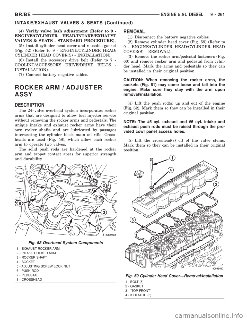
The 24±valve overhead system incorporates rocker
arms that are designed to allow fuel injector service
without removing the rocker arms and pedestals. The
unique intake and exhaust rocker arms have their
own rocker shafts and are lubricated by passages
intersecting the cylinder block main oil rifle. Cross-
heads are used (Fig. 58), which allow each rocker
arm to operate two valves.
The solid push rods are hardened at the rocker
arm and tappet contact areas for superior strength
and durability.
REMOVAL
(1) Disconnect the battery negative cables.
(2) Remove cylinder head cover (Fig. 59) (Refer to
9 - ENGINE/CYLINDER HEAD/CYLINDER HEAD
COVER(S) - REMOVAL).
(3) Remove the rocker arm/pedestal fasteners (Fig.
60) and remove rocker arm and pedestal from cylin-
der head. Mark the arms and pedestals so they can
be installed in their original position.
CAUTION: When removing the rocker arms, the
sockets (Fig. 61) may come loose and fall into the
engine. Make sure they stay with the arm upon
removal/installation.
(4) Lift the push rod(s) up and out of the engine
(Fig. 62). Mark them so they can be installed in their
original position.
NOTE: The #5 cyl. exhaust and #6 cyl. intake and
exhaust push rods must be raised through the pro-
vided cowl panel access holes.
(5) Lift the crosshead(s) off of the valve stems.
Mark them so they can be installed in their original
position.
Fig. 58 Overhead System Components
1 - EXHAUST ROCKER ARM
2 - INTAKE ROCKER ARM
3 - ROCKER SHAFT
4 - SOCKET
5 - ADJUSTING SCREW LOCK NUT
6 - PUSH ROD
7 - PEDESTAL
8 - CROSSHEAD
Fig. 59 Cylinder Head CoverÐRemoval/Installation
1 - BOLT (5)
2 - GASKET
3 - ªTOP FRONTº
4 - ISOLATOR (5)
BR/BEENGINE 5.9L DIESEL 9 - 261
INTAKE/EXHAUST VALVES & SEATS (Continued)