2001 DODGE RAM service
[x] Cancel search: servicePage 1318 of 2889
ENGINE 8.0L
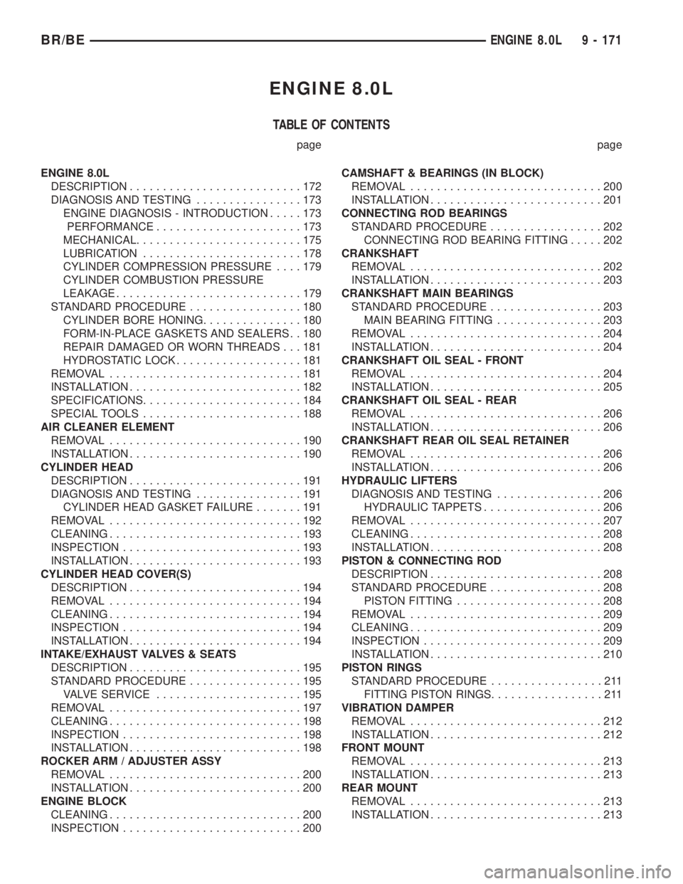
TABLE OF CONTENTS
page page
ENGINE 8.0L
DESCRIPTION..........................172
DIAGNOSIS AND TESTING................173
ENGINE DIAGNOSIS - INTRODUCTION.....173
PERFORMANCE......................173
MECHANICAL.........................175
LUBRICATION........................178
CYLINDER COMPRESSION PRESSURE....179
CYLINDER COMBUSTION PRESSURE
LEAKAGE............................179
STANDARD PROCEDURE.................180
CYLINDER BORE HONING...............180
FORM-IN-PLACE GASKETS AND SEALERS . . 180
REPAIR DAMAGED OR WORN THREADS . . . 181
HYDROSTATIC LOCK...................181
REMOVAL.............................181
INSTALLATION..........................182
SPECIFICATIONS........................184
SPECIAL TOOLS........................188
AIR CLEANER ELEMENT
REMOVAL.............................190
INSTALLATION..........................190
CYLINDER HEAD
DESCRIPTION..........................191
DIAGNOSIS AND TESTING................191
CYLINDER HEAD GASKET FAILURE.......191
REMOVAL.............................192
CLEANING.............................193
INSPECTION...........................193
INSTALLATION..........................193
CYLINDER HEAD COVER(S)
DESCRIPTION..........................194
REMOVAL.............................194
CLEANING.............................194
INSPECTION...........................194
INSTALLATION..........................194
INTAKE/EXHAUST VALVES & SEATS
DESCRIPTION..........................195
STANDARD PROCEDURE.................195
VALVE SERVICE......................195
REMOVAL.............................197
CLEANING.............................198
INSPECTION...........................198
INSTALLATION..........................198
ROCKER ARM / ADJUSTER ASSY
REMOVAL.............................200
INSTALLATION..........................200
ENGINE BLOCK
CLEANING.............................200
INSPECTION...........................200CAMSHAFT & BEARINGS (IN BLOCK)
REMOVAL.............................200
INSTALLATION..........................201
CONNECTING ROD BEARINGS
STANDARD PROCEDURE.................202
CONNECTING ROD BEARING FITTING.....202
CRANKSHAFT
REMOVAL.............................202
INSTALLATION..........................203
CRANKSHAFT MAIN BEARINGS
STANDARD PROCEDURE.................203
MAIN BEARING FITTING................203
REMOVAL.............................204
INSTALLATION..........................204
CRANKSHAFT OIL SEAL - FRONT
REMOVAL.............................204
INSTALLATION..........................205
CRANKSHAFT OIL SEAL - REAR
REMOVAL.............................206
INSTALLATION..........................206
CRANKSHAFT REAR OIL SEAL RETAINER
REMOVAL.............................206
INSTALLATION..........................206
HYDRAULIC LIFTERS
DIAGNOSIS AND TESTING................206
HYDRAULIC TAPPETS..................206
REMOVAL.............................207
CLEANING.............................208
INSTALLATION..........................208
PISTON & CONNECTING ROD
DESCRIPTION..........................208
STANDARD PROCEDURE.................208
PISTON FITTING......................208
REMOVAL.............................209
CLEANING.............................209
INSPECTION...........................209
INSTALLATION..........................210
PISTON RINGS
STANDARD PROCEDURE.................211
FITTING PISTON RINGS.................211
VIBRATION DAMPER
REMOVAL.............................212
INSTALLATION..........................212
FRONT MOUNT
REMOVAL.............................213
INSTALLATION..........................213
REAR MOUNT
REMOVAL.............................213
INSTALLATION..........................213
BR/BEENGINE 8.0L 9 - 171
Page 1320 of 2889
DIAGNOSIS AND TESTINGÐENGINE
DIAGNOSIS - INTRODUCTION
Engine diagnosis is helpful in determining the
causes of malfunctions not detected and remedied by
routine maintenance.
These malfunctions may be classified as either
mechanical (e.g., a strange noise), or performance
(e.g., engine idles rough and stalls).
(Refer to 9 - ENGINE - DIAGNOSIS AND TEST-
ING - Preformance) or (Refer to 9 - ENGINE - DIAG-
NOSIS AND TESTING - Mechanical). Refer to 14 -
FUEL SYSTEM for fuel system diagnosis.Additional tests and diagnostic procedures may be
necessary for specific engine malfunctions that can-
not be isolated with the Service Diagnosis charts.
Information concerning additional tests and diagno-
sis is provided within the following:
²Cylinder Compression Pressure Test
²Cylinder Combustion Pressure Leakage Test
²Cylinder Head Gasket Failure Diagnosis
²Intake Manifold Leakage Diagnosis
²Lash Adjuster (Tappet) Noise Diagnosis
²Engine Oil Leak Inspection
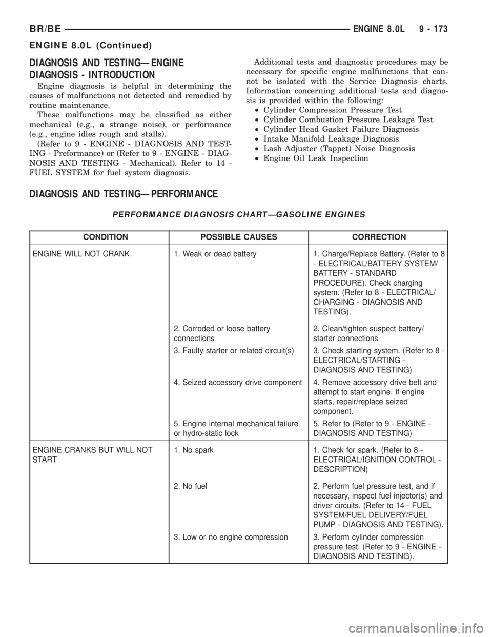
DIAGNOSIS AND TESTINGÐPERFORMANCE
PERFORMANCE DIAGNOSIS CHARTÐGASOLINE ENGINES
CONDITION POSSIBLE CAUSES CORRECTION
ENGINE WILL NOT CRANK 1. Weak or dead battery 1. Charge/Replace Battery. (Refer to 8
- ELECTRICAL/BATTERY SYSTEM/
BATTERY - STANDARD
PROCEDURE). Check charging
system. (Refer to 8 - ELECTRICAL/
CHARGING - DIAGNOSIS AND
TESTING).
2. Corroded or loose battery
connections2. Clean/tighten suspect battery/
starter connections
3. Faulty starter or related circuit(s) 3. Check starting system. (Refer to 8 -
ELECTRICAL/STARTING -
DIAGNOSIS AND TESTING)
4. Seized accessory drive component 4. Remove accessory drive belt and
attempt to start engine. If engine
starts, repair/replace seized
component.
5. Engine internal mechanical failure
or hydro-static lock5. Refer to (Refer to 9 - ENGINE -
DIAGNOSIS AND TESTING)
ENGINE CRANKS BUT WILL NOT
START1. No spark 1. Check for spark. (Refer to 8 -
ELECTRICAL/IGNITION CONTROL -
DESCRIPTION)
2. No fuel 2. Perform fuel pressure test, and if
necessary, inspect fuel injector(s) and
driver circuits. (Refer to 14 - FUEL
SYSTEM/FUEL DELIVERY/FUEL
PUMP - DIAGNOSIS AND TESTING).
3. Low or no engine compression 3. Perform cylinder compression
pressure test. (Refer to 9 - ENGINE -
DIAGNOSIS AND TESTING).
BR/BEENGINE 8.0L 9 - 173
ENGINE 8.0L (Continued)
Page 1331 of 2889
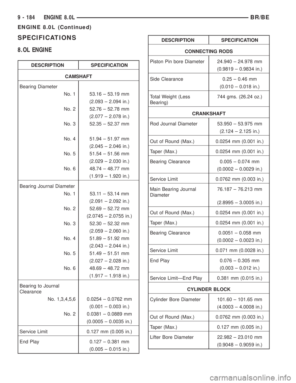
SPECIFICATIONS
8.OL ENGINE
DESCRIPTION SPECIFICATION
CAMSHAFT
Bearing Diameter
No. 1 53.16 ± 53.19 mm
(2.093 ± 2.094 in.)
No. 2 52.76 ± 52.78 mm
(2.077 ± 2.078 in.)
No. 3 52.35 ± 52.37 mm
No. 4 51.94 ± 51.97 mm
(2.045 ± 2.046 in.)
No. 5 51.54 ± 51.56 mm
(2.029 ± 2.030 in.)
No. 6 48.74 ± 48.77 mm
(1.919 ± 1.920 in.)
Bearing Journal Diameter
No. 1 53.11 ± 53.14 mm
(2.091 ± 2.092 in.)
No. 2 52.69 ± 52.72 mm
(2.0745 ± 2.0755 in.)
No. 3 52.30 ± 52.32 mm
(2.059 ± 2.060 in.)
No. 4 51.89 ± 51.92 mm
(2.043 ± 2.044 in.)
No. 5 51.49 ± 51.51 mm
(2.027 ± 2.028 in.)
No. 6 48.69 ± 48.72 mm
(1.917 ± 1.918 in.)
Bearing to Journal
Clearance
No. 1,3,4,5,6 0.0254 ± 0.0762 mm
(0.001 ± 0.003 in.)
No. 2 0.0381 ± 0.0889 mm
(0.0005 ± 0.0035 in.)
Service Limit 0.127 mm (0.005 in.)
End Play 0.127 ± 0.381 mm
(0.005 ± 0.015 in.)
DESCRIPTION SPECIFICATION
CONNECTING RODS
Piston Pin bore Diameter 24.940 ± 24.978 mm
(0.9819 ± 0.9834 in.)
Side Clearance 0.25 ± 0.46 mm
(0.010 ± 0.018 in.)
Total Weight (Less
Bearing)744 gms. (26.24 oz.)
CRANKSHAFT
Rod Journal Diameter 53.950 ± 53.975 mm
(2.124 ± 2.125 in.)
Out of Round (Max.) 0.0254 mm (0.001 in.)
Taper (Max.) 0.0254 mm (0.001 in.)
Bearing Clearance 0.005 ± 0.074 mm
(0.0002 ± 0.0029 in.)
Service Limit 0.0762 mm (0.003 in.)
Main Bearing Journal
Diameter76.187 ± 76.213 mm
(2.8995 ± 3.0005 in.)
Out of Round (Max.) 0.0254 mm (0.001 in.)
Taper (Max.) 0.0254 mm (0.001 in.)
Bearing Clearance 0.0051 ± 0.058 mm
(0.0002 ± 0.0023 in.)
Service Limit 0.071 mm (0.0028 in.)
End Play 0.076 ± 0.305 mm
(0.003 ± 0.012 in.)
Service LimitÐEnd Play 0.381 mm (0.015 in.)
CYLINDER BLOCK
Cylinder Bore Diameter 101.60 ± 101.65 mm
(4.0003 ± 4.0008 in.)
Out of Round (Max.) 0.0762 mm (0.003 in.)
Taper (Max.) 0.127 mm (0.005 in.)
Lifter Bore Diameter 22.982 ± 23.010 mm
(0.9048 ± 0.9059 in.)
9 - 184 ENGINE 8.0LBR/BE
ENGINE 8.0L (Continued)
Page 1332 of 2889
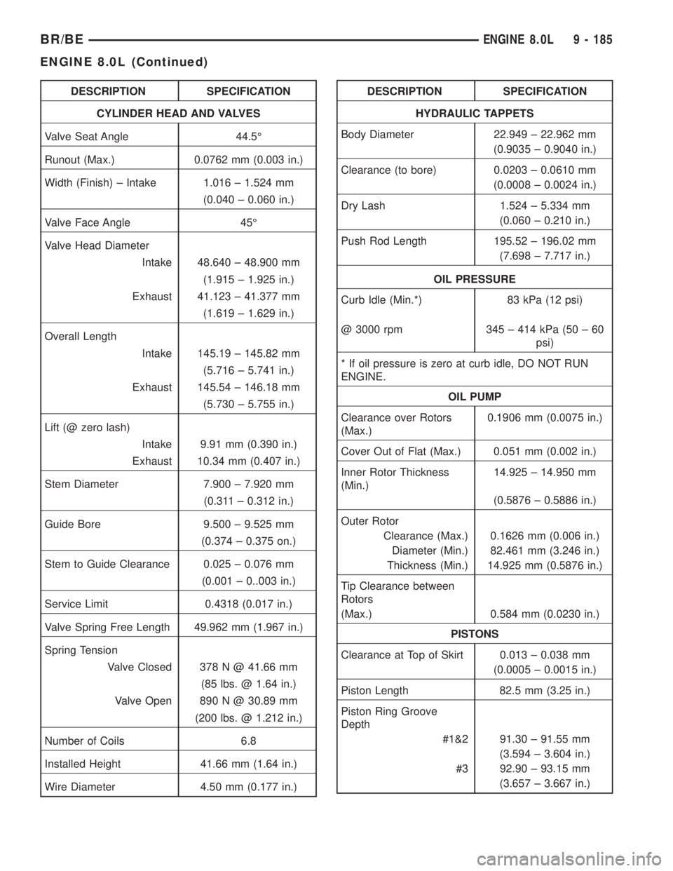
DESCRIPTION SPECIFICATION
CYLINDER HEAD AND VALVES
Valve Seat Angle 44.5É
Runout (Max.) 0.0762 mm (0.003 in.)
Width (Finish) ± Intake 1.016 ± 1.524 mm
(0.040 ± 0.060 in.)
Valve Face Angle 45É
Valve Head Diameter
Intake 48.640 ± 48.900 mm
(1.915 ± 1.925 in.)
Exhaust 41.123 ± 41.377 mm
(1.619 ± 1.629 in.)
Overall Length
Intake 145.19 ± 145.82 mm
(5.716 ± 5.741 in.)
Exhaust 145.54 ± 146.18 mm
(5.730 ± 5.755 in.)
Lift (@ zero lash)
Intake 9.91 mm (0.390 in.)
Exhaust 10.34 mm (0.407 in.)
Stem Diameter 7.900 ± 7.920 mm
(0.311 ± 0.312 in.)
Guide Bore 9.500 ± 9.525 mm
(0.374 ± 0.375 on.)
Stem to Guide Clearance 0.025 ± 0.076 mm
(0.001 ± 0..003 in.)
Service Limit 0.4318 (0.017 in.)
Valve Spring Free Length 49.962 mm (1.967 in.)
Spring Tension
Valve Closed 378 N @ 41.66 mm
(85 lbs. @ 1.64 in.)
Valve Open 890 N @ 30.89 mm
(200 lbs. @ 1.212 in.)
Number of Coils 6.8
Installed Height 41.66 mm (1.64 in.)
Wire Diameter 4.50 mm (0.177 in.)DESCRIPTION SPECIFICATION
HYDRAULIC TAPPETS
Body Diameter 22.949 ± 22.962 mm
(0.9035 ± 0.9040 in.)
Clearance (to bore) 0.0203 ± 0.0610 mm
(0.0008 ± 0.0024 in.)
Dry Lash 1.524 ± 5.334 mm
(0.060 ± 0.210 in.)
Push Rod Length 195.52 ± 196.02 mm
(7.698 ± 7.717 in.)
OIL PRESSURE
Curb Idle (Min.*) 83 kPa (12 psi)
@ 3000 rpm 345 ± 414 kPa (50 ± 60
psi)
* If oil pressure is zero at curb idle, DO NOT RUN
ENGINE.
OIL PUMP
Clearance over Rotors
(Max.)0.1906 mm (0.0075 in.)
Cover Out of Flat (Max.) 0.051 mm (0.002 in.)
Inner Rotor Thickness
(Min.)14.925 ± 14.950 mm
(0.5876 ± 0.5886 in.)
Outer Rotor
Clearance (Max.) 0.1626 mm (0.006 in.)
Diameter (Min.) 82.461 mm (3.246 in.)
Thickness (Min.) 14.925 mm (0.5876 in.)
Tip Clearance between
Rotors
(Max.) 0.584 mm (0.0230 in.)
PISTONS
Clearance at Top of Skirt 0.013 ± 0.038 mm
(0.0005 ± 0.0015 in.)
Piston Length 82.5 mm (3.25 in.)
Piston Ring Groove
Depth
#1&2 91.30 ± 91.55 mm
(3.594 ± 3.604 in.)
#3 92.90 ± 93.15 mm
(3.657 ± 3.667 in.)
BR/BEENGINE 8.0L 9 - 185
ENGINE 8.0L (Continued)
Page 1333 of 2889
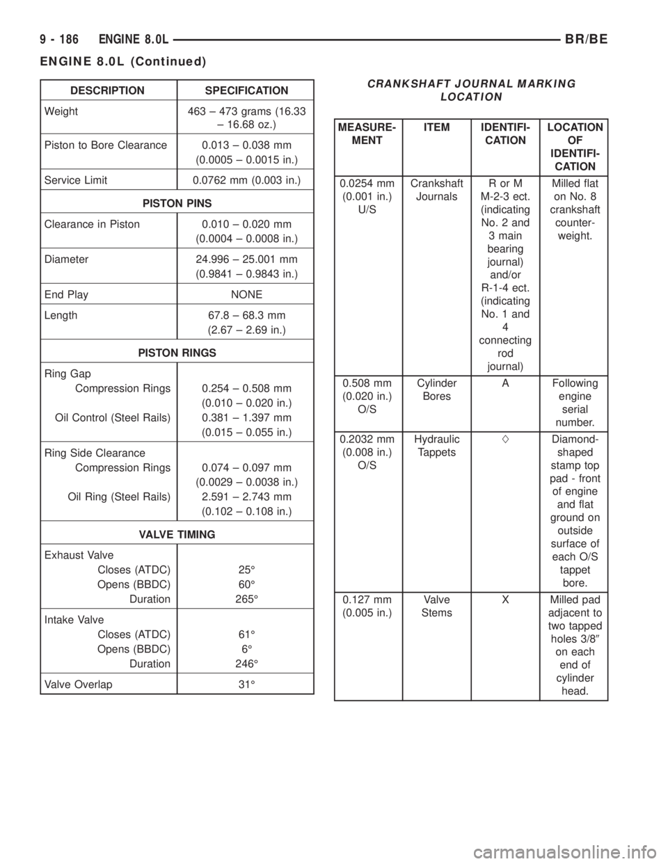
DESCRIPTION SPECIFICATION
Weight 463 ± 473 grams (16.33
± 16.68 oz.)
Piston to Bore Clearance 0.013 ± 0.038 mm
(0.0005 ± 0.0015 in.)
Service Limit 0.0762 mm (0.003 in.)
PISTON PINS
Clearance in Piston 0.010 ± 0.020 mm
(0.0004 ± 0.0008 in.)
Diameter 24.996 ± 25.001 mm
(0.9841 ± 0.9843 in.)
End Play NONE
Length 67.8 ± 68.3 mm
(2.67 ± 2.69 in.)
PISTON RINGS
Ring Gap
Compression Rings 0.254 ± 0.508 mm
(0.010 ± 0.020 in.)
Oil Control (Steel Rails) 0.381 ± 1.397 mm
(0.015 ± 0.055 in.)
Ring Side Clearance
Compression Rings 0.074 ± 0.097 mm
(0.0029 ± 0.0038 in.)
Oil Ring (Steel Rails) 2.591 ± 2.743 mm
(0.102 ± 0.108 in.)
VALVE TIMING
Exhaust Valve
Closes (ATDC) 25É
Opens (BBDC) 60É
Duration 265É
Intake Valve
Closes (ATDC) 61É
Opens (BBDC) 6É
Duration 246É
Valve Overlap 31ÉCRANKSHAFT JOURNAL MARKING
LOCATION
MEASURE-
MENTITEM IDENTIFI-
CATIONLOCATION
OF
IDENTIFI-
CATION
0.0254 mm
(0.001 in.)
U/SCrankshaft
JournalsRorM
M-2-3 ect.
(indicating
No. 2 and
3 main
bearing
journal)
and/or
R-1-4 ect.
(indicating
No. 1 and
4
connecting
rod
journal)Milled flat
on No. 8
crankshaft
counter-
weight.
0.508 mm
(0.020 in.)
O/SCylinder
BoresA Following
engine
serial
number.
0.2032 mm
(0.008 in.)
O/SHydraulic
TappetsLDiamond-
shaped
stamp top
pad - front
of engine
and flat
ground on
outside
surface of
each O/S
tappet
bore.
0.127 mm
(0.005 in.)Valve
StemsX Milled pad
adjacent to
two tapped
holes 3/89
on each
end of
cylinder
head.
9 - 186 ENGINE 8.0LBR/BE
ENGINE 8.0L (Continued)
Page 1342 of 2889
(5) Install closed crankcase ventilation system and
evaporation control system onto the proper head
cover. DO NOT switch the systems.
(6) Connect the negative cable to the battery.
(7) Start engine and check for leaks.
INTAKE/EXHAUST VALVES &
SEATS
DESCRIPTION
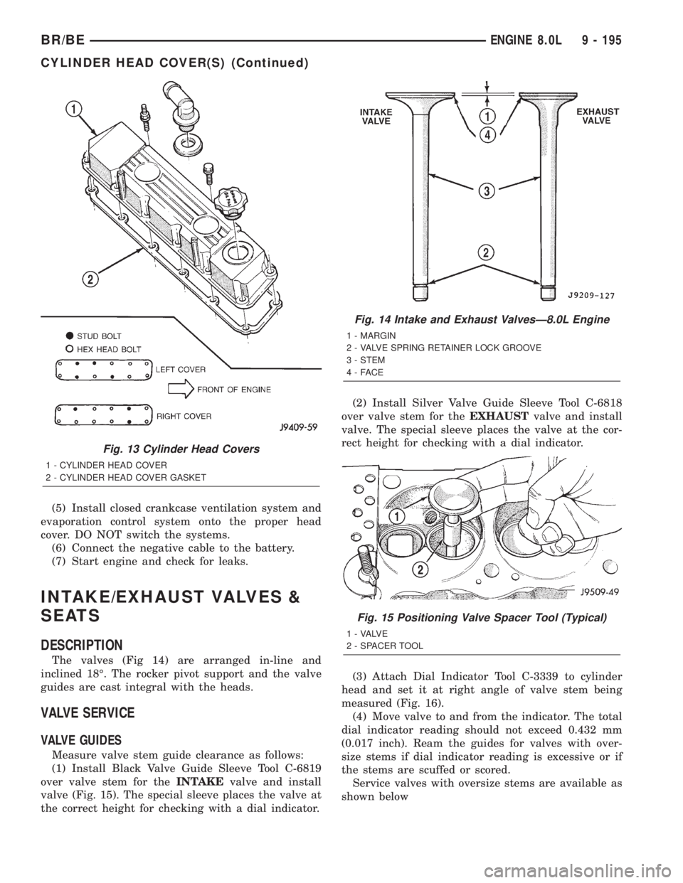
The valves (Fig 14) are arranged in-line and
inclined 18É. The rocker pivot support and the valve
guides are cast integral with the heads.
VALVE SERVICE
VALVE GUIDES
Measure valve stem guide clearance as follows:
(1) Install Black Valve Guide Sleeve Tool C-6819
over valve stem for theINTAKEvalve and install
valve (Fig. 15). The special sleeve places the valve at
the correct height for checking with a dial indicator.(2) Install Silver Valve Guide Sleeve Tool C-6818
over valve stem for theEXHAUSTvalve and install
valve. The special sleeve places the valve at the cor-
rect height for checking with a dial indicator.
(3) Attach Dial Indicator Tool C-3339 to cylinder
head and set it at right angle of valve stem being
measured (Fig. 16).
(4) Move valve to and from the indicator. The total
dial indicator reading should not exceed 0.432 mm
(0.017 inch). Ream the guides for valves with over-
size stems if dial indicator reading is excessive or if
the stems are scuffed or scored.
Service valves with oversize stems are available as
shown below
Fig. 13 Cylinder Head Covers
1 - CYLINDER HEAD COVER
2 - CYLINDER HEAD COVER GASKET
Fig. 14 Intake and Exhaust ValvesÐ8.0L Engine
1 - MARGIN
2 - VALVE SPRING RETAINER LOCK GROOVE
3 - STEM
4-FACE
Fig. 15 Positioning Valve Spacer Tool (Typical)
1 - VALVE
2 - SPACER TOOL
BR/BEENGINE 8.0L 9 - 195
CYLINDER HEAD COVER(S) (Continued)
Page 1351 of 2889
REMOVAL
(1) Remove the oil pan and oil pump pick-up tube
(Refer to 9 - ENGINE/LUBRICATION/OIL PAN -
REMOVAL).
(2) Identify bearing caps before removal. Remove
bearing caps one at a time.
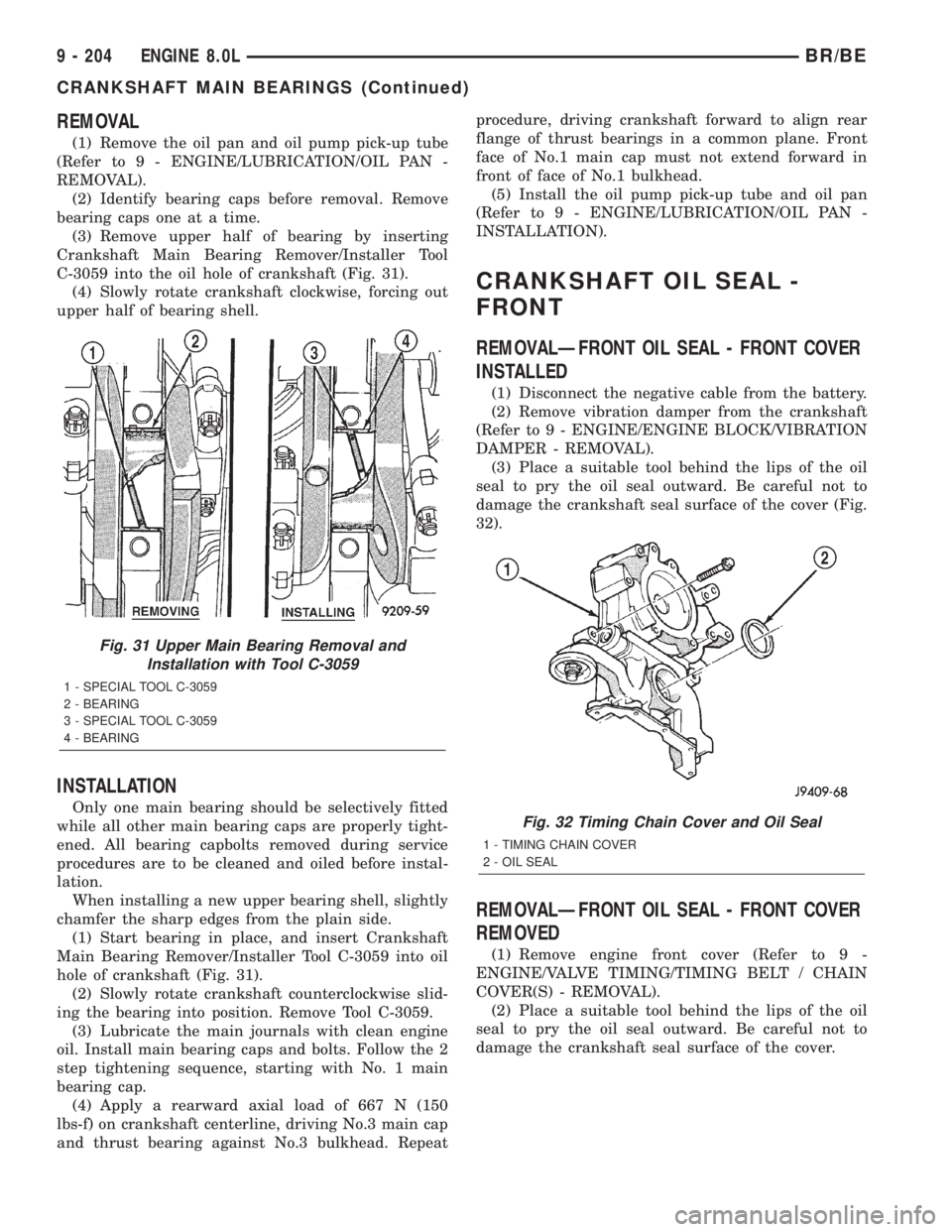
(3) Remove upper half of bearing by inserting
Crankshaft Main Bearing Remover/Installer Tool
C-3059 into the oil hole of crankshaft (Fig. 31).
(4) Slowly rotate crankshaft clockwise, forcing out
upper half of bearing shell.
INSTALLATION
Only one main bearing should be selectively fitted
while all other main bearing caps are properly tight-
ened. All bearing capbolts removed during service
procedures are to be cleaned and oiled before instal-
lation.
When installing a new upper bearing shell, slightly
chamfer the sharp edges from the plain side.
(1) Start bearing in place, and insert Crankshaft
Main Bearing Remover/Installer Tool C-3059 into oil
hole of crankshaft (Fig. 31).
(2) Slowly rotate crankshaft counterclockwise slid-
ing the bearing into position. Remove Tool C-3059.
(3) Lubricate the main journals with clean engine
oil. Install main bearing caps and bolts. Follow the 2
step tightening sequence, starting with No. 1 main
bearing cap.
(4) Apply a rearward axial load of 667 N (150
lbs-f) on crankshaft centerline, driving No.3 main cap
and thrust bearing against No.3 bulkhead. Repeatprocedure, driving crankshaft forward to align rear
flange of thrust bearings in a common plane. Front
face of No.1 main cap must not extend forward in
front of face of No.1 bulkhead.
(5) Install the oil pump pick-up tube and oil pan
(Refer to 9 - ENGINE/LUBRICATION/OIL PAN -
INSTALLATION).
CRANKSHAFT OIL SEAL -
FRONT
REMOVALÐFRONT OIL SEAL - FRONT COVER
INSTALLED
(1) Disconnect the negative cable from the battery.
(2) Remove vibration damper from the crankshaft
(Refer to 9 - ENGINE/ENGINE BLOCK/VIBRATION
DAMPER - REMOVAL).
(3) Place a suitable tool behind the lips of the oil
seal to pry the oil seal outward. Be careful not to
damage the crankshaft seal surface of the cover (Fig.
32).
REMOVALÐFRONT OIL SEAL - FRONT COVER
REMOVED
(1) Remove engine front cover (Refer to 9 -
ENGINE/VALVE TIMING/TIMING BELT / CHAIN
COVER(S) - REMOVAL).
(2) Place a suitable tool behind the lips of the oil
seal to pry the oil seal outward. Be careful not to
damage the crankshaft seal surface of the cover.
Fig. 31 Upper Main Bearing Removal and
Installation with Tool C-3059
1 - SPECIAL TOOL C-3059
2 - BEARING
3 - SPECIAL TOOL C-3059
4 - BEARING
Fig. 32 Timing Chain Cover and Oil Seal
1 - TIMING CHAIN COVER
2 - OIL SEAL
9 - 204 ENGINE 8.0LBR/BE
CRANKSHAFT MAIN BEARINGS (Continued)
Page 1362 of 2889
rotates. This oil throwoff lubricates the camshaft
lobes, cylinder walls, and piston pins.
The hydraulic valve tappets receive oil directly
from the main oil gallery. The camshaft bearings
receive oil from the main bearing galleries. The front
camshaft bearing journal passes oil through the cam-
shaft sprocket to the timing chain. Oil drains back to
the oil pan under the No. 1 main bearing cap.
The oil supply for the rocker arms and bridged
pivot assemblies is provided by the hydraulic valve
tappets, which pass oil through hollow push rods to a
hole in the corresponding rocker arm. Oil from the
rocker arm lubricates the valve train components.
The oil then passes down through the push rod guide
holes and the oil drain-back passages in the cylinder
head, past the valve tappet area, and then returns to
the oil pan (Fig. 52).
DIAGNOSIS AND TESTINGÐENGINE OIL
LEAKS
Begin with a through visual inspection of the
engine, particularly at the area of the suspected leak.
If an oil leak source is not readily identifiable, the
following steps should be followed:
(1) Do not clean or degrease the engine at this
time because some solvents may cause rubber to
swell, temporarily stopping the leak.
(2) Add an oil-soluble dye (use as recommended by
manufacturer). Start the engine and let idle for
approximately 15 minutes. Check the oil dipstick to
be sure the dye is thoroughly mixed as indicated
with a bright yellow color under a black light source.
(3) Using a black light, inspect the entire engine
for fluorescent dye, particularly at the suspected area
of oil leak. If the oil leak is found and identified,
repair per service manual instructions.
(4) If dye is not observed, drive the vehicle at var-
ious speeds for approximately 24km (15 miles), and
repeat previous step.(5) If the oil leak source is not positively identified
at this time, proceed with the air leak detection test
method as follows:
(6) Disconnect the breather cap to air cleaner hose
at the breather cap end. Cap or plug breather cap
nipple.
(7) Remove the PCV valve from the cylinder head
cover. Cap or plug the PCV valve grommet.
(8) Attach an air hose with pressure gauge and
regulator to the dipstick tube.
CAUTION: Do not subject the engine assembly to
more than 20.6 kpa (3 PSI) of test pressure.
(9) Gradually apply air pressure from 1 psi to 2.5
psi maximum while applying soapy water at the sus-
pected source. Adjust the regulator to the suitable
test pressure that provide the best bubbles which
will pinpoint the leak source. If the oil leak is
detected and identified, repair per service manual
procedures.
(10) If the leakage occurs at the rear oil seal area,
refer to the section, Inspection for Rear Seal Area
Leak.
(11) If no leaks are detected, turn off the air sup-
ply and remove the air hose and all plugs and caps.
Install the PCV valve and breather cap hose. Proceed
to next step.
(12) Clean the oil off the suspect oil leak area
using a suitable solvent. Drive the vehicle at various
speeds approximately 24 km (15 miles). Inspect the
engine for signs of an oil leak by using a black light.
DIAGNOSIS AND TESTINGÐENGINE OIL
PRESSURE
(1) Remove oil pressure sending unit.
(2) Install Oil Pressure Line and Gauge Tool
C-3292. Start engine and record pressure. (Refer to 9
- ENGINE - SPECIFICATIONS).
BR/BEENGINE 8.0L 9 - 215
LUBRICATION (Continued)