2001 DODGE RAM service
[x] Cancel search: servicePage 1157 of 2889
DIAGNOSIS AND TESTINGÐREAR SEAL AREA
LEAKS
Since it is sometimes difficult to determine the
source of an oil leak in the rear seal area of the
engine, a more involved inspection is necessary. The
following steps should be followed to help pinpoint
the source of the leak.
If the leakage occurs at the crankshaft rear oil seal
area:
(1) Disconnect the battery.
(2) Raise the vehicle.
(3) Remove torque converter or clutch housing
cover and inspect rear of block for evidence of oil.
Use a black light to check for the oil leak:
(a) Circular spray pattern generally indicates
seal leakage or crankshaft damage.
(b) Where leakage tends to run straight down,
possible causes are a porous block, distributor seal,
camshaft bore cup plugs, oil galley pipe plugs, oil
filter runoff, and main bearing cap to cylinder
block mating surfaces.
(4) If no leaks are detected, pressurized the crank-
case as outlined in (Refer to 9 - ENGINE/LUBRICA-
TION - DIAGNOSIS AND TESTING)
CAUTION: Do not exceed 20.6 kPa (3 psi).
(5) If the leak is not detected, very slowly turn the
crankshaft and watch for leakage. If a leak is
detected between the crankshaft and seal while
slowly turning the crankshaft, it is possible the
crankshaft seal surface is damaged. The seal area on
the crankshaft could have minor nicks or scratches
that can be polished out with emery cloth.
CAUTION: Use extreme caution when crankshaft
polishing is necessary to remove minor nicks or
scratches. The crankshaft seal flange is specially
machined to complement the function of the rear oil
seal.
(6) For bubbles that remain steady with shaft
rotation, no further inspection can be done until dis-
assembled. Refer to the service DiagnosisÐMechani-
cal, under the Oil Leak row, for components
inspections on possible causes and corrections.
(7) After the oil leak root cause and appropriate
corrective action have been identified, (Refer to 9 -
ENGINE/ENGINE BLOCK/CRANKSHAFT OIL
SEAL - REAR - REMOVAL), for proper replacement
procedures.
STANDARD PROCEDUREÐCYLINDER BORE
HONING
Before honing, stuff plenty of clean shop towels
under the bores and over the crankshaft to keep
abrasive materials from entering the crankshaft
area.
(1) Used carefully, the Cylinder Bore Sizing Hone
C-823, equipped with 220 grit stones, is the best tool
for this job. In addition to deglazing, it will reduce
taper and out-of-round, as well as removing light
scuffing, scoring and scratches. Usually, a few strokes
will clean up a bore and maintain the required lim-
its.
CAUTION: DO NOT use rigid type hones to remove
cylinder wall glaze.
(2) Deglazing of the cylinder walls may be done if
the cylinder bore is straight and round. Use a cylin-
der surfacing hone, Honing Tool C-3501, equipped
with 280 grit stones (C-3501-3810). about 20-60
strokes, depending on the bore condition, will be suf-
ficient to provide a satisfactory surface. Using honing
oil C-3501-3880, or a light honing oil, available from
major oil distributors.
CAUTION: DO NOT use engine or transmission oil,
mineral spirits, or kerosene.
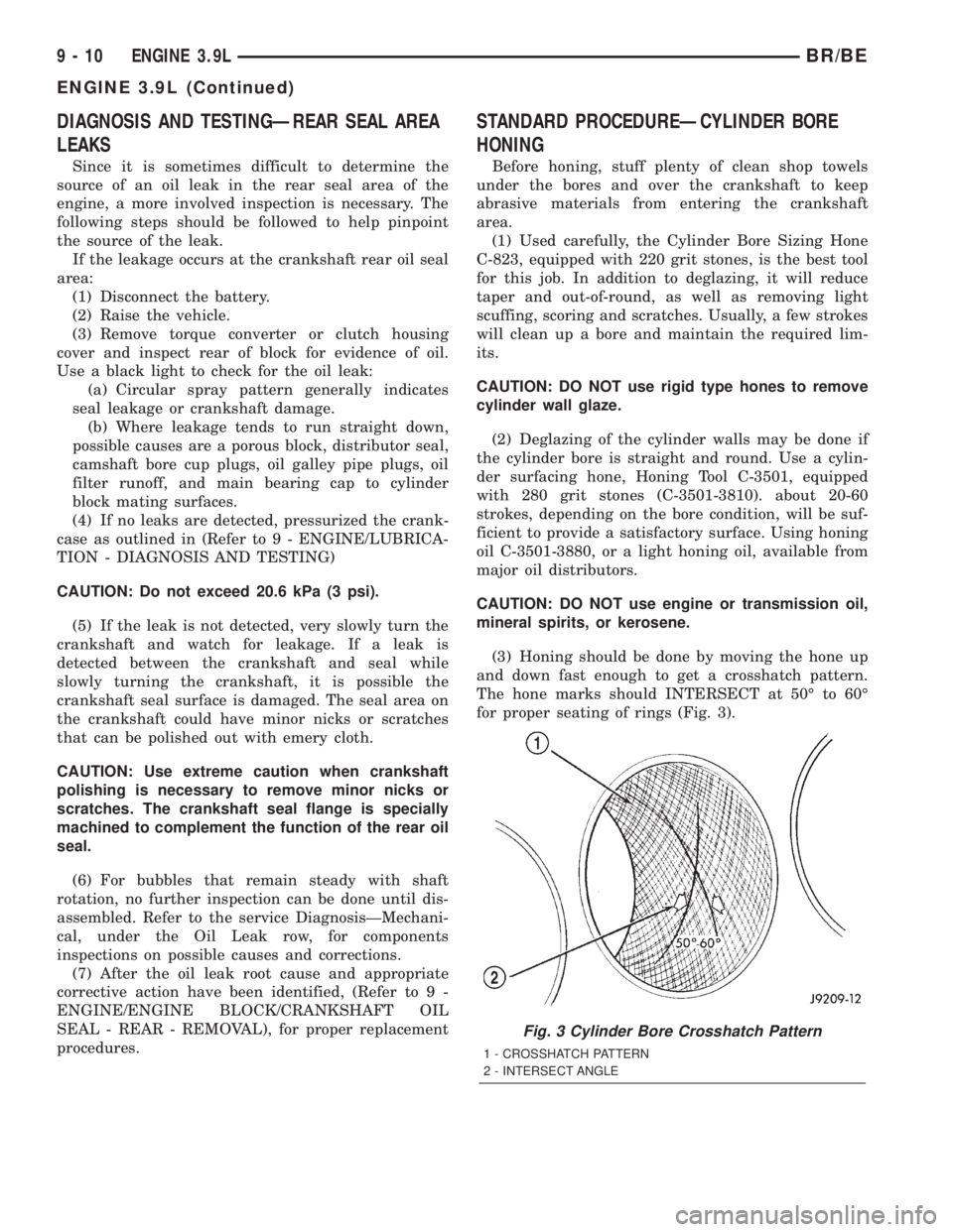
(3) Honing should be done by moving the hone up
and down fast enough to get a crosshatch pattern.
The hone marks should INTERSECT at 50É to 60É
for proper seating of rings (Fig. 3).
Fig. 3 Cylinder Bore Crosshatch Pattern
1 - CROSSHATCH PATTERN
2 - INTERSECT ANGLE
9 - 10 ENGINE 3.9LBR/BE
ENGINE 3.9L (Continued)
Page 1161 of 2889
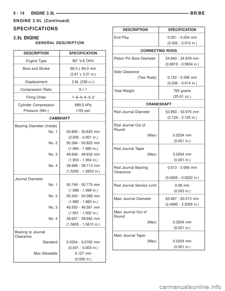
SPECIFICATIONS
3.9L ENGINE
GENERAL DESCRIPTION
DESCRIPTION SPECIFICATION
Engine Type 90É V-6 OHV
Bore and Stroke 99.3 x 84.0 mm
(3.91 x 3.31 in.)
Displacement 3.9L (238 c.i.)
Compression Ratio 9.1:1
Firing Order 1±6±5±4±3±2
Cylinder Compression 689.5 kPa
Pressure (Min.) (100 psi)
CAMSHAFT
Bearing Diameter (Inside)
No. 1 50.800 - 50.825 mm
(2.000 - 2.001 in.)
No. 2 50.394 - 50.825 mm
(1.984 - 1.985 in.)
No. 3 49.606 - 49.632 mm
(1.953 - 1.954 in.)
No. 4 39.688 - 39.713 mm
(1.5265 - 1.5653 in.)
Journal Diameter
No. 1 50.749 - 50.775 mm
(1.998 - 1.999 in.)
No. 2 50.343 - 50.368 mm
(1.982 - 1.983 in.)
No. 3 49.555 - 49.581 mm
(1.951 - 1.952 in.)
No. 4 39.637 - 39.662 mm
(1.5605 - 1.5615 in.)
Bearing to Journal
Clearance
Standard 0.0254 - 0.0762 mm
(0.001 - 0.003 in.)
Max Allowable 0.127 mm
(0.005 in.)
DESCRIPTION SPECIFICATION
End Play 0.051 - 0.254 mm
(0.002 - 0.010 in.)
CONNECTING RODS
Piston Pin Bore Diameter 24.940 - 24.978 mm
(0.9819 - 0.9834 in.)
Side Clearance
(Two Rods) 0.152 - 0.356 mm
(0.006 - 0.014 in.)
Total Weight 762 grams
(25.61 oz.)
CRANKSHAFT
Rod Journal Diameter 53.950 - 53.975 mm
(2.124 - 2.125 in.)
Rod Journal Out of
Round
(Max) 0.0254 mm
(0.001 in.)
Rod Journal Taper
(Max) 0.0254 mm
(0.001 in.)
Rod Journal Bearing
Clearance0.013 - 0.056 mm
(0.0005 - 0.0022 in.)
Rod Journal Service Limit 0.08 mm
(0.003 in.)
Main Journal Diameter 63.487 - 63.513 mm
(2.4995 - 2.5005 in.)
Main Journal Out of
Round
(Max) 0.0254 mm
(0.001 in.)
Main Journal Taper
(Max) 0.0254 mm
(0.001 in.)
9 - 14 ENGINE 3.9LBR/BE
ENGINE 3.9L (Continued)
Page 1162 of 2889
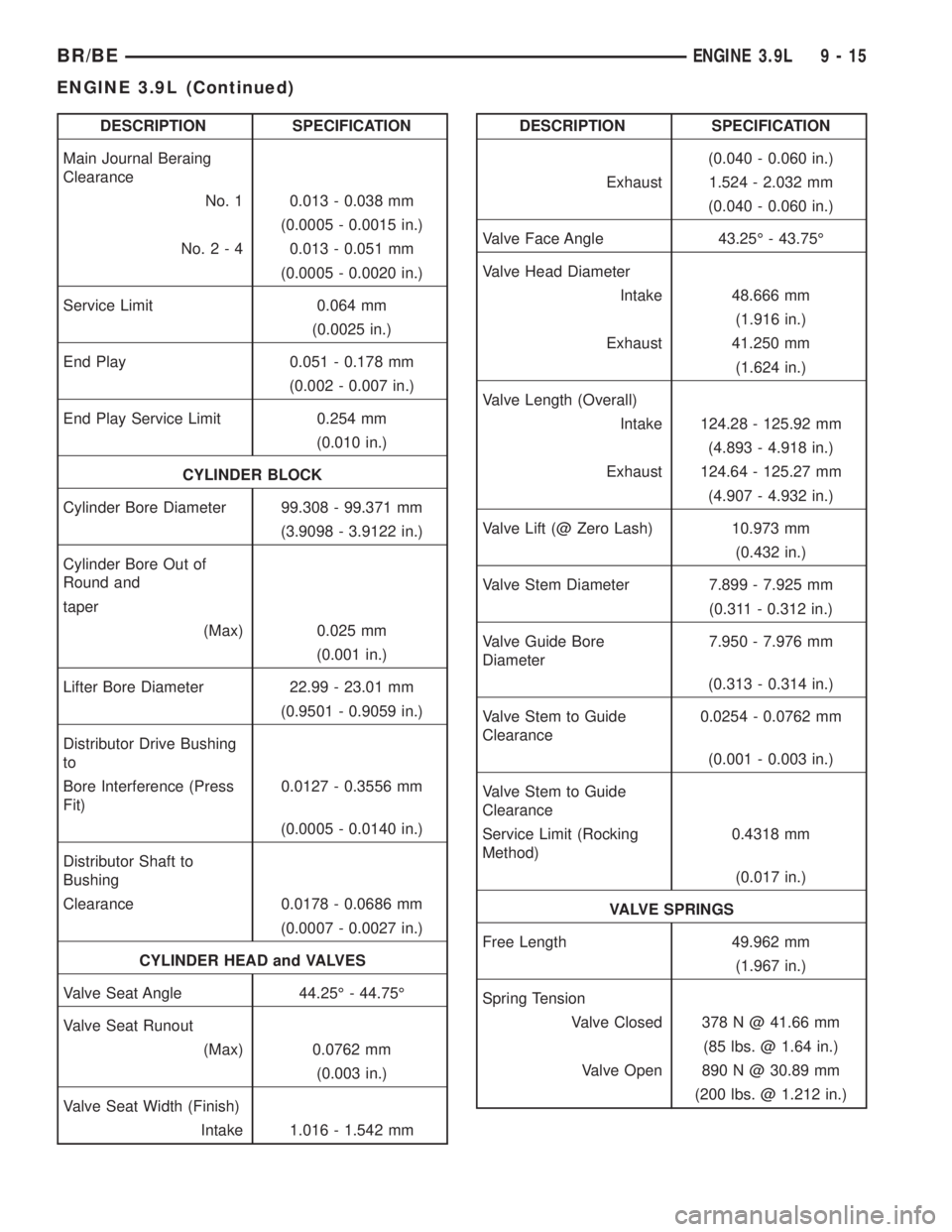
DESCRIPTION SPECIFICATION
Main Journal Beraing
Clearance
No. 1 0.013 - 0.038 mm
(0.0005 - 0.0015 in.)
No.2-40.013 - 0.051 mm
(0.0005 - 0.0020 in.)
Service Limit 0.064 mm
(0.0025 in.)
End Play 0.051 - 0.178 mm
(0.002 - 0.007 in.)
End Play Service Limit 0.254 mm
(0.010 in.)
CYLINDER BLOCK
Cylinder Bore Diameter 99.308 - 99.371 mm
(3.9098 - 3.9122 in.)
Cylinder Bore Out of
Round and
taper
(Max) 0.025 mm
(0.001 in.)
Lifter Bore Diameter 22.99 - 23.01 mm
(0.9501 - 0.9059 in.)
Distributor Drive Bushing
to
Bore Interference (Press
Fit)0.0127 - 0.3556 mm
(0.0005 - 0.0140 in.)
Distributor Shaft to
Bushing
Clearance 0.0178 - 0.0686 mm
(0.0007 - 0.0027 in.)
CYLINDER HEAD and VALVES
Valve Seat Angle 44.25É - 44.75É
Valve Seat Runout
(Max) 0.0762 mm
(0.003 in.)
Valve Seat Width (Finish)
Intake 1.016 - 1.542 mmDESCRIPTION SPECIFICATION
(0.040 - 0.060 in.)
Exhaust 1.524 - 2.032 mm
(0.040 - 0.060 in.)
Valve Face Angle 43.25É - 43.75É
Valve Head Diameter
Intake 48.666 mm
(1.916 in.)
Exhaust 41.250 mm
(1.624 in.)
Valve Length (Overall)
Intake 124.28 - 125.92 mm
(4.893 - 4.918 in.)
Exhaust 124.64 - 125.27 mm
(4.907 - 4.932 in.)
Valve Lift (@ Zero Lash) 10.973 mm
(0.432 in.)
Valve Stem Diameter 7.899 - 7.925 mm
(0.311 - 0.312 in.)
Valve Guide Bore
Diameter7.950 - 7.976 mm
(0.313 - 0.314 in.)
Valve Stem to Guide
Clearance0.0254 - 0.0762 mm
(0.001 - 0.003 in.)
Valve Stem to Guide
Clearance
Service Limit (Rocking
Method)0.4318 mm
(0.017 in.)
VALVE SPRINGS
Free Length 49.962 mm
(1.967 in.)
Spring Tension
Valve Closed 378 N @ 41.66 mm
(85 lbs. @ 1.64 in.)
Valve Open 890 N @ 30.89 mm
(200 lbs. @ 1.212 in.)
BR/BEENGINE 3.9L 9 - 15
ENGINE 3.9L (Continued)
Page 1172 of 2889
INTAKE/EXHAUST VALVES &
SEATS
DESCRIPTION
Both the intake and exhaust valves are made of
steel. The intake valve is 48.768 mm (1.92 inches) in
diameter and the exhaust valve is 41.148 mm (1.62
inches) in diameter and has a 2.032 mm (0.080 inch)
wafer interia welded to the tip for durability. These
valves are not splayed.
STANDARD PROCEDUREÐVALVES, GUIDES
AND SPRINGS
VALVE CLEANING
Clean valves thoroughly. Discard burned, warped,
or cracked valves.
Remove carbon and varnish deposits from inside of
valve guides with a reliable guide cleaner.
VALVE GUIDES
Measure valve stems for wear. If wear exceeds
0.051 mm (0.002 in.), replace the valve.
Measure valve stem guide clearance as follows:
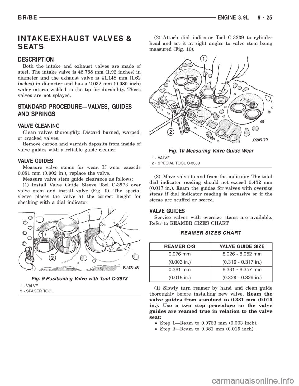
(1) Install Valve Guide Sleeve Tool C-3973 over
valve stem and install valve (Fig. 9). The special
sleeve places the valve at the correct height for
checking with a dial indicator.(2) Attach dial indicator Tool C-3339 to cylinder
head and set it at right angles to valve stem being
measured (Fig. 10).
(3) Move valve to and from the indicator. The total
dial indicator reading should not exceed 0.432 mm
(0.017 in.). Ream the guides for valves with oversize
stems if dial indicator reading is excessive or if the
stems are scuffed or scored.
VALVE GUIDES
Service valves with oversize stems are available.
Refer to REAMER SIZES CHART
REAMER SIZES CHART
REAMER O/S VALVE GUIDE SIZE
0.076 mm 8.026 - 8.052 mm
(0.003 in.) (0.316 - 0.317 in.)
0.381 mm 8.331 - 8.357 mm
(0.015 in.) (0.328 - 0.329 in.)
(1) Slowly turn reamer by hand and clean guide
thoroughly before installing new valve.Ream the
valve guides from standard to 0.381 mm (0.015
in.). Use a two step procedure so the valve
guides are reamed true in relation to the valve
seat:
²Step 1ÐReam to 0.0763 mm (0.003 inch).
²Step 2ÐReam to 0.381 mm (0.015 inch).
Fig. 9 Positioning Valve with Tool C-3973
1 - VALVE
2 - SPACER TOOL
Fig. 10 Measuring Valve Guide Wear
1 - VALVE
2 - SPECIAL TOOL C-3339
BR/BEENGINE 3.9L 9 - 25
Page 1175 of 2889
INSTALLATION
(1) Clean valves thoroughly. Discard burned,
warped and cracked valves.
(2) Remove carbon and varnish deposits from
inside of valve guides with a reliable guide cleaner.
(3) Measure valve stems for wear. If wear exceeds
0.051 mm (0.002 inch), replace the valve.
(4) Coat valve stems with lubrication oil and insert
them in cylinder head.
(5) If valves or seats are reground, check valve
stem height. If valve is too long, replace cylinder
head.
(6) Install new seals on all valve guides. Install
valve springs and valve retainers.
(7) Compress valve springs with Valve Spring
Compressor Tool MD-998772A and adapter 6716A,
install locks and release tool. If valves and/or seats
are ground, measure the installed height of springs.
Make sure the measurement is taken from bottom of
spring seat in cylinder head to the bottom surface of
spring retainer. If spacers are installed, measure
from the top of spacer. If height is greater than 42.86
mm (1-11/16 inches), install a 1.587 mm (1/16 inch)
spacer in head counterbore. This should bring spring
height back to normal 41.27 to 42.86 mm (1-5/8 to
1-11/16 inch).
(8) Install cylinder head (Refer to 9 - ENGINE/
CYLINDER HEAD - INSTALLATION).
ENGINE BLOCK
CLEANING
Clean cylinder block thoroughly and check all core
hole plugs for evidence of leakage.
INSPECTION
Examine block for cracks or fractures.
The cylinder walls should be checked for out-of-
round and taper. Refer to Honing Cylinder Bores in
the Service Procedures portion of this Section.
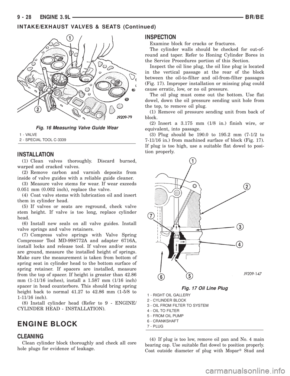
Inspect the oil line plug, the oil line plug is located
in the vertical passage at the rear of the block
between the oil-to-filter and oil-from-filter passages
(Fig. 17). Improper installation or missing plug could
cause erratic, low, or no oil pressure.
The oil plug must come out the bottom. Use flat
dowel, down the oil pressure sending unit hole from
the top, to remove oil plug.
(1) Remove oil pressure sending unit from back of
block.
(2) Insert a 3.175 mm (1/8 in.) finish wire, or
equivalent, into passage.
(3) Plug should be 190.0 to 195.2 mm (7-1/2 to
7-11/16 in.) from machined surface of block (Fig. 17).
If plug is too high, use a suitable flat dowel to posi-
tion properly.
(4)
If plug is too low, remove oil pan and No. 4 main
bearing cap. Use suitable flat dowel to position properly.
Coat outside diameter of plug with MopartStud and
Fig. 16 Measuring Valve Guide Wear
1 - VALVE
2 - SPECIAL TOOL C-3339
Fig. 17 Oil Line Plug
1 - RIGHT OIL GALLERY
2 - CYLINDER BLOCK
3 - OIL FROM FILTER TO SYSTEM
4 - OIL TO FILTER
5 - FROM OIL PUMP
6 - CRANKSHAFT
7 - PLUG
9 - 28 ENGINE 3.9LBR/BE
INTAKE/EXHAUST VALVES & SEATS (Continued)
Page 1181 of 2889
INSTALLATION
Only one main bearing should be selectively fitted
while all other main bearing caps are properly tight-
ened. All bearing capbolts removed during service
procedures are to be cleaned and oiled before instal-
lation. DO NOT use a new bearing half with an old
bearing half.
When installing a new upper bearing shell, slightly
chamfer the sharp edges from the plain side.
(1) Start bearing in place, and insert Crankshaft
Main Bearing Remover/Installer Tool C-3059 into oil
hole of crankshaft (Fig. 29).
(2) Slowly rotate crankshaft counterclockwise slid-
ing the bearing into position. Remove Tool C-3059.
(3) Install the bearing caps. Clean and oil the
bolts. Tighten the capbolts to 115 N´m (85 ft. lbs.)
torque.
(4) Install the oil pump (Refer to 9 - ENGINE/LU-
BRICATION/OIL PUMP - INSTALLATION).
(5) Install the oil pan (Refer to 9 - ENGINE/LU-
BRICATION/OIL PAN - INSTALLATION).
CRANKSHAFT OIL SEAL -
FRONT
DESCRIPTION
The crankshaft rear seal is a two piece viton seal.
The crankshaft front seal is a one piece viton seal
with a steel housing. The front seal is located in the
engine front cover. One part of the two piece rear
seal is located in a slot in the number four (4) crank-
shaft main bore, the second part of the two piece seal
is located in the number four (4) main bearing cap.
OPERATION
The crankshaft seals prevent oil from leaking from
around the crankshaft, either from the rear of the
engine or from the engine front cover.
REMOVAL
The oil seal can be replaced without removing the
timing chain cover, provided that the cover is not
misaligned.
(1) Disconnect the negative cable from the battery.
(2) Remove vibration damper (Refer to 9 -
ENGINE/ENGINE BLOCK/VIBRATION DAMPER -
REMOVAL).
(3) If front seal is suspected of leaking, check front
oil seal alignment to crankshaft. The seal installa-
tion/alignment Tool 6635, should fit with minimum
interference. If tool does not fit, the cover must be
removed and installed properly.
(4) Place a suitable tool behind the lips of the oil
seal to pry the oil seal outward. Be careful not to
damage the crankshaft seal bore of cover.
INSTALLATION
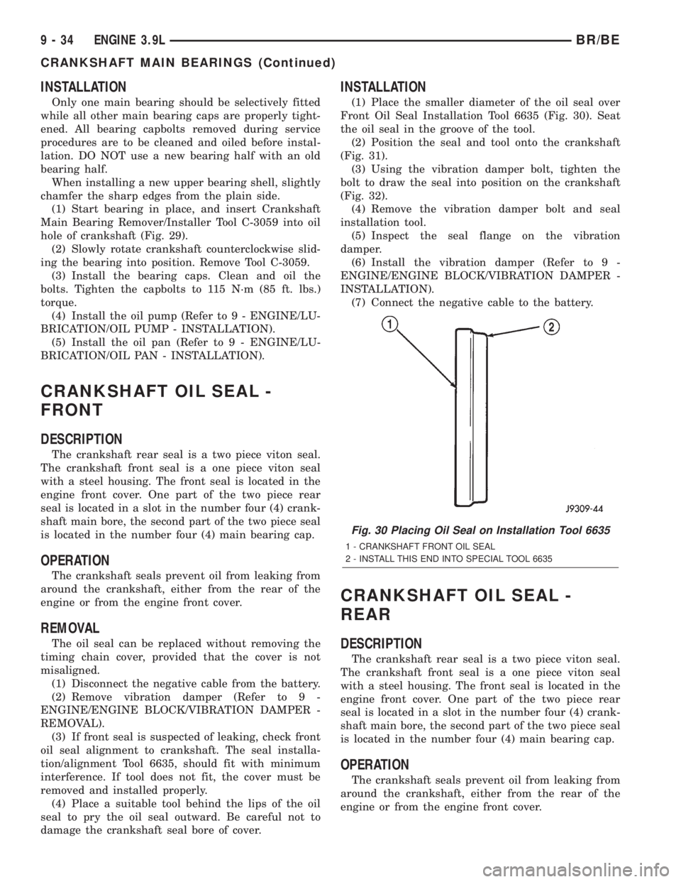
(1) Place the smaller diameter of the oil seal over
Front Oil Seal Installation Tool 6635 (Fig. 30). Seat
the oil seal in the groove of the tool.
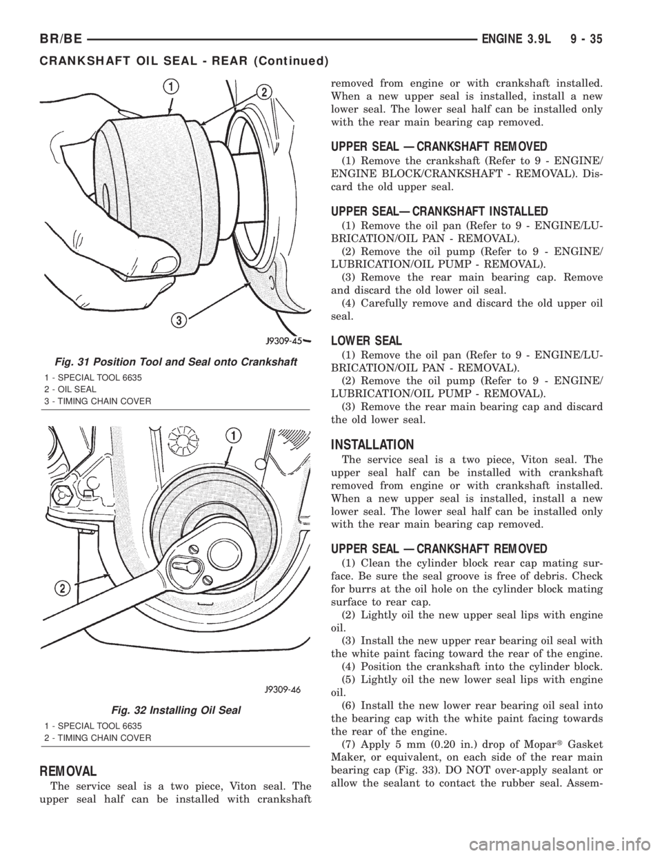
(2) Position the seal and tool onto the crankshaft
(Fig. 31).
(3) Using the vibration damper bolt, tighten the
bolt to draw the seal into position on the crankshaft
(Fig. 32).
(4) Remove the vibration damper bolt and seal
installation tool.
(5) Inspect the seal flange on the vibration
damper.
(6) Install the vibration damper (Refer to 9 -
ENGINE/ENGINE BLOCK/VIBRATION DAMPER -
INSTALLATION).
(7) Connect the negative cable to the battery.
CRANKSHAFT OIL SEAL -
REAR
DESCRIPTION
The crankshaft rear seal is a two piece viton seal.
The crankshaft front seal is a one piece viton seal
with a steel housing. The front seal is located in the
engine front cover. One part of the two piece rear
seal is located in a slot in the number four (4) crank-
shaft main bore, the second part of the two piece seal
is located in the number four (4) main bearing cap.
OPERATION
The crankshaft seals prevent oil from leaking from
around the crankshaft, either from the rear of the
engine or from the engine front cover.
Fig. 30 Placing Oil Seal on Installation Tool 6635
1 - CRANKSHAFT FRONT OIL SEAL
2 - INSTALL THIS END INTO SPECIAL TOOL 6635
9 - 34 ENGINE 3.9LBR/BE
CRANKSHAFT MAIN BEARINGS (Continued)
Page 1182 of 2889
REMOVAL
The service seal is a two piece, Viton seal. The
upper seal half can be installed with crankshaftremoved from engine or with crankshaft installed.
When a new upper seal is installed, install a new
lower seal. The lower seal half can be installed only
with the rear main bearing cap removed.
UPPER SEAL ÐCRANKSHAFT REMOVED
(1) Remove the crankshaft (Refer to 9 - ENGINE/
ENGINE BLOCK/CRANKSHAFT - REMOVAL). Dis-
card the old upper seal.
UPPER SEALÐCRANKSHAFT INSTALLED
(1) Remove the oil pan (Refer to 9 - ENGINE/LU-
BRICATION/OIL PAN - REMOVAL).
(2) Remove the oil pump (Refer to 9 - ENGINE/
LUBRICATION/OIL PUMP - REMOVAL).
(3) Remove the rear main bearing cap. Remove
and discard the old lower oil seal.
(4) Carefully remove and discard the old upper oil
seal.
LOWER SEAL
(1) Remove the oil pan (Refer to 9 - ENGINE/LU-
BRICATION/OIL PAN - REMOVAL).
(2) Remove the oil pump (Refer to 9 - ENGINE/
LUBRICATION/OIL PUMP - REMOVAL).
(3) Remove the rear main bearing cap and discard
the old lower seal.
INSTALLATION
The service seal is a two piece, Viton seal. The
upper seal half can be installed with crankshaft
removed from engine or with crankshaft installed.
When a new upper seal is installed, install a new
lower seal. The lower seal half can be installed only
with the rear main bearing cap removed.
UPPER SEAL ÐCRANKSHAFT REMOVED
(1) Clean the cylinder block rear cap mating sur-
face. Be sure the seal groove is free of debris. Check
for burrs at the oil hole on the cylinder block mating
surface to rear cap.
(2) Lightly oil the new upper seal lips with engine
oil.
(3) Install the new upper rear bearing oil seal with
the white paint facing toward the rear of the engine.
(4) Position the crankshaft into the cylinder block.
(5) Lightly oil the new lower seal lips with engine
oil.
(6) Install the new lower rear bearing oil seal into
the bearing cap with the white paint facing towards
the rear of the engine.
(7) Apply 5 mm (0.20 in.) drop of MopartGasket
Maker, or equivalent, on each side of the rear main
bearing cap (Fig. 33). DO NOT over-apply sealant or
allow the sealant to contact the rubber seal. Assem-
Fig. 31 Position Tool and Seal onto Crankshaft
1 - SPECIAL TOOL 6635
2 - OIL SEAL
3 - TIMING CHAIN COVER
Fig. 32 Installing Oil Seal
1 - SPECIAL TOOL 6635
2 - TIMING CHAIN COVER
BR/BEENGINE 3.9L 9 - 35
CRANKSHAFT OIL SEAL - REAR (Continued)
Page 1194 of 2889
DIAGNOSIS AND TESTINGÐENGINE OIL
PRESSURE
(1) Remove oil pressure sending unit.
(2) Install Oil Pressure Line and Gauge Tool
C-3292. Start engine and record pressure. (Refer to 9
- ENGINE - SPECIFICATIONS).
DIAGNOSIS AND TESTINGÐENGINE OIL
LEAKS
Begin with a through visual inspection of the
engine, particularly at the area of the suspected leak.
If an oil leak source is not readily identifiable, the
following steps should be followed:
(1) Do not clean or degrease the engine at this
time because some solvents may cause rubber to
swell, temporarily stopping the leak.
(2) Add an oil-soluble dye (use as recommended by
manufacturer). Start the engine and let idle for
approximately 15 minutes. Check the oil dipstick to
be sure the dye is thoroughly mixed as indicated
with a bright yellow color under a black light source.
(3) Using a black light, inspect the entire engine
for fluorescent dye, particularly at the suspected area
of oil leak. If the oil leak is found and identified,
repair per service manual instructions.
(4) If dye is not observed, drive the vehicle at var-
ious speeds for approximately 24km (15 miles), and
repeat previous step.
(5) If the oil leak source is not positively identified
at this time, proceed with the air leak detection test
method as follows:
(6) Disconnect the breather cap to air cleaner hose
at the breather cap end. Cap or plug breather cap
nipple.
(7) Remove the PCV valve from the cylinder head
cover. Cap or plug the PCV valve grommet.
(8) Attach an air hose with pressure gauge and
regulator to the dipstick tube.
CAUTION: Do not subject the engine assembly to
more than 20.6 kpa (3 PSI) of test pressure.
(9) Gradually apply air pressure from 1 psi to 2.5
psi maximum while applying soapy water at the sus-
pected source. Adjust the regulator to the suitable
test pressure that provide the best bubbles which
will pinpoint the leak source. If the oil leak is
detected and identified, repair per service manual
procedures.
(10) If the leakage occurs at the rear oil seal area,
refer to the section, Inspection for Rear Seal Area
Leak.
(11) If no leaks are detected, turn off the air sup-
ply and remove the air hose and all plugs and caps.
Install the PCV valve and breather cap hose. Proceed
to next step.(12) Clean the oil off the suspect oil leak area
using a suitable solvent. Drive the vehicle at various
speeds approximately 24 km (15 miles). Inspect the
engine for signs of an oil leak by using a black light.
OIL
STANDARD PROCEDUREÐENGINE OIL
OIL LEVEL INDICATOR (DIPSTICK)
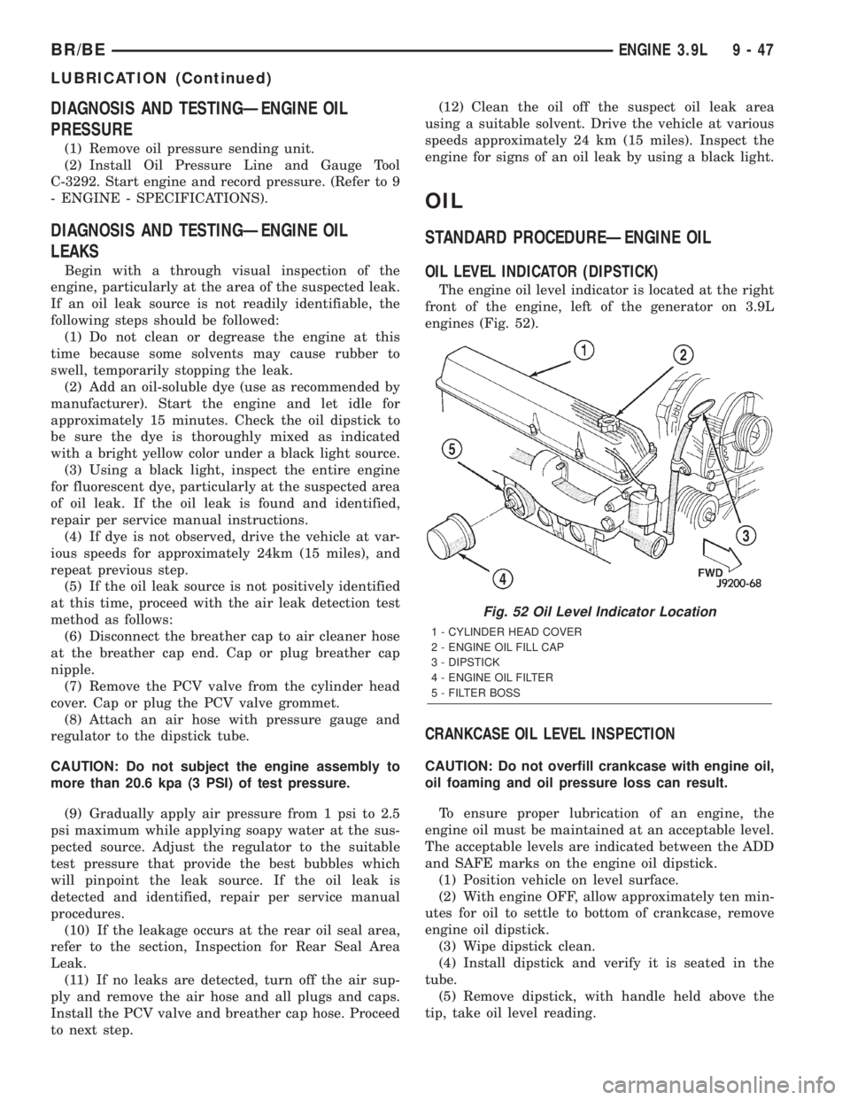
The engine oil level indicator is located at the right
front of the engine, left of the generator on 3.9L
engines (Fig. 52).
CRANKCASE OIL LEVEL INSPECTION
CAUTION: Do not overfill crankcase with engine oil,
oil foaming and oil pressure loss can result.
To ensure proper lubrication of an engine, the
engine oil must be maintained at an acceptable level.
The acceptable levels are indicated between the ADD
and SAFE marks on the engine oil dipstick.
(1) Position vehicle on level surface.
(2) With engine OFF, allow approximately ten min-
utes for oil to settle to bottom of crankcase, remove
engine oil dipstick.
(3) Wipe dipstick clean.
(4) Install dipstick and verify it is seated in the
tube.
(5) Remove dipstick, with handle held above the
tip, take oil level reading.
Fig. 52 Oil Level Indicator Location
1 - CYLINDER HEAD COVER
2 - ENGINE OIL FILL CAP
3 - DIPSTICK
4 - ENGINE OIL FILTER
5 - FILTER BOSS
BR/BEENGINE 3.9L 9 - 47
LUBRICATION (Continued)