2001 DODGE RAM service
[x] Cancel search: servicePage 697 of 2889
WARNING: WHEN REMOVING A DEPLOYED AIR-
BAG, RUBBER GLOVES, EYE PROTECTION, AND A
LONG-SLEEVED SHIRT SHOULD BE WORN. THERE
MAY BE DEPOSITS ON THE AIRBAG UNIT AND
OTHER INTERIOR SURFACES. IN LARGE DOSES,
THESE DEPOSITS MAY CAUSE IRRITATION TO THE
SKIN AND EYES.
(1) Disconnect and isolate the battery negative
cable. If either of the airbags has not been deployed,
wait two minutes for the system capacitor to dis-
charge before further service.
(2) Remove the glove box from the instrument
panel. (Refer to 23 - BODY/INSTRUMENT PANEL/
GLOVE BOX - REMOVAL).
(3) Remove the glove box opening upper trim from
the instrument panel. (Refer to 23 - BODY/INSTRU-
MENT PANEL/GLOVE BOX OPENING UPPER
TRIM - REMOVAL).
(4) Remove the four screws that secure the two
plastic support brackets for the passenger airbag
door panel outlet housing to the glove box opening
upper reinforcement.
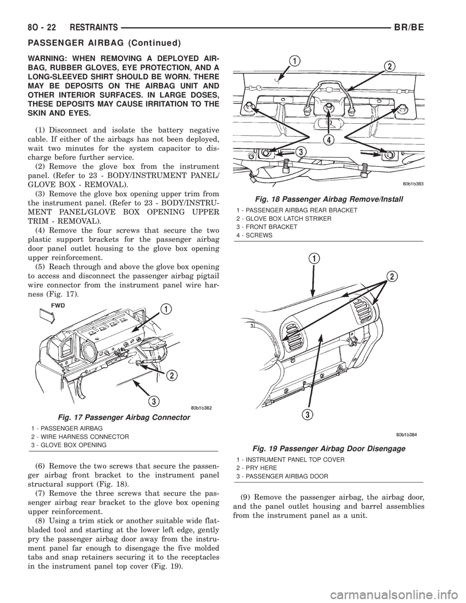
(5) Reach through and above the glove box opening
to access and disconnect the passenger airbag pigtail
wire connector from the instrument panel wire har-
ness (Fig. 17).
(6) Remove the two screws that secure the passen-
ger airbag front bracket to the instrument panel
structural support (Fig. 18).
(7) Remove the three screws that secure the pas-
senger airbag rear bracket to the glove box opening
upper reinforcement.
(8)
Using a trim stick or another suitable wide flat-
bladed tool and starting at the lower left edge, gently
pry the passenger airbag door away from the instru-
ment panel far enough to disengage the five molded
tabs and snap retainers securing it to the receptacles
in the instrument panel top cover (Fig. 19).
(9) Remove the passenger airbag, the airbag door,
and the panel outlet housing and barrel assemblies
from the instrument panel as a unit.
Fig. 17 Passenger Airbag Connector
1 - PASSENGER AIRBAG
2 - WIRE HARNESS CONNECTOR
3 - GLOVE BOX OPENING
Fig. 18 Passenger Airbag Remove/Install
1 - PASSENGER AIRBAG REAR BRACKET
2 - GLOVE BOX LATCH STRIKER
3 - FRONT BRACKET
4 - SCREWS
Fig. 19 Passenger Airbag Door Disengage
1 - INSTRUMENT PANEL TOP COVER
2 - PRY HERE
3 - PASSENGER AIRBAG DOOR
8O - 22 RESTRAINTSBR/BE
PASSENGER AIRBAG (Continued)
Page 698 of 2889
INSTALLATION
WARNING: DISABLE THE AIRBAG SYSTEM
BEFORE ATTEMPTING ANY STEERING WHEEL,
STEERING COLUMN, OR INSTRUMENT PANEL
COMPONENT DIAGNOSIS OR SERVICE. DISCON-
NECT AND ISOLATE THE BATTERY NEGATIVE
(GROUND) CABLE, THEN WAIT TWO MINUTES FOR
THE AIRBAG SYSTEM CAPACITOR TO DISCHARGE
BEFORE PERFORMING FURTHER DIAGNOSIS OR
SERVICE. THIS IS THE ONLY SURE WAY TO DIS-
ABLE THE AIRBAG SYSTEM. FAILURE TO TAKE
THE PROPER PRECAUTIONS COULD RESULT IN
ACCIDENTAL AIRBAG DEPLOYMENT AND POSSI-
BLE PERSONAL INJURY.
WARNING: WHEN REMOVING A DEPLOYED AIR-
BAG, RUBBER GLOVES, EYE PROTECTION, AND A
LONG-SLEEVED SHIRT SHOULD BE WORN. THERE
MAY BE DEPOSITS ON THE AIRBAG UNIT AND
OTHER INTERIOR SURFACES. IN LARGE DOSES,
THESE DEPOSITS MAY CAUSE IRRITATION TO THE
SKIN AND EYES.
WARNING: USE EXTREME CARE TO PREVENT ANY
FOREIGN MATERIAL FROM ENTERING THE PAS-
SENGER AIRBAG, OR BECOMING ENTRAPPED
BETWEEN THE PASSENGER AIRBAG CUSHION
AND THE PASSENGER AIRBAG DOOR. FAILURE TO
OBSERVE THIS WARNING COULD RESULT IN
OCCUPANT INJURIES UPON AIRBAG DEPLOY-
MENT.
WARNING: THE PASSENGER AIRBAG DOOR MUST
NEVER BE PAINTED. REPLACEMENT PASSENGER
AIRBAG DOORS ARE SERVICED IN THE ORIGINAL
COLORS. PAINT MAY CHANGE THE WAY IN WHICH
THE MATERIAL OF THE AIRBAG DOOR RESPONDS
TO AN AIRBAG DEPLOYMENT. FAILURE TO
OBSERVE THIS WARNING COULD RESULT IN
OCCUPANT INJURIES UPON AIRBAG DEPLOY-
MENT.
(1) Carefully inspect the five receptacle slots
around the top and sides of the passenger airbag
door opening of the instrument panel top cover.
Remove any of the small metal airbag door snap
retainers that did not remain on the molded airbag
door tabs during the removal procedure.
(2) If the removed passenger airbag module is
being reinstalled, install the metal snap retainers
recovered in Step 1onto the proper airbag door tabs.
Each of the five molded airbag door tabs must have a
snap retainer on it before it is installed in the instru-ment panel. New replacement passenger airbags
come with new airbag door snap retainers installed.
(3) Carefully position the passenger airbag onto
the instrument panel.
(4) Align the five tabs and retainers on the upper
edge and sides of the passenger airbag door with the
receptacles in the instrument panel top cover.
(5) Using hand pressure, press firmly on the pas-
senger airbag door over each of the tab and retainer
locations until each of them is fully engaged in its
receptacle. Be certain that each of the metal snap
retainers is in position on the airbag door tabs.
(6) Install and tighten the five screws that secure
the passenger airbag front and rear mounting brack-
ets to the instrument panel (Fig. 18). Tighten the
screws to 9 N´m (80 in. lbs.).
(7) Install and tighten the four screws that secure
the two plastic support brackets of the passenger air-
bag door panel outlet housing to the glove box open-
ing upper reinforcement. Tighten the screws to 2.2
N´m (20 in. lbs.).
(8) Reach through and above the glove box opening
to access and reconnect the passenger airbag pigtail
wire connector to the instrument panel wire harness
connector (Fig. 17). Be certain that the passenger air-
bag pigtail wire connector is fully engaged with and
latched to the instrument panel wire harness connec-
tor.
(9) Reinstall the glove box opening upper trim onto
the instrument panel. (Refer to 23 - BODY/INSTRU-
MENT PANEL/GLOVE BOX OPENING UPPER
TRIM - INSTALLATION).
(10) Reinstall the glove box onto the instrument
panel. (Refer to 23 - BODY/INSTRUMENT PANEL/
GLOVE BOX - INSTALLATION).
(11) Do not reconnect the battery negative cable at
this time. The airbag system verification test proce-
dure should be performed following service of any
airbag system component. (Refer to 8 - ELECTRI-
CAL/RESTRAINTS - STANDARD PROCEDURE -
VERIFICATION TEST).
PASSENGER AIRBAG ON/OFF
SWITCH
DESCRIPTION
The passenger airbag on-off switch is standard
equipment on this model when it is not equipped
with a full size rear seat. This switch is a single pole,
single throw switch with a single integral red Light-
Emitting Diode (LED), and a non-coded key cylinder-
type actuator. The switch is located in the upper
right corner of instrument panel cluster bezel, near
the center of instrument panel to make the Off indi-
cator visible to all front seat occupants. When the
BR/BERESTRAINTS 8O - 23
PASSENGER AIRBAG (Continued)
Page 699 of 2889
switch is in its installed position, the only compo-
nents visible through the dedicated opening of the
cluster bezel are the switch face plate and nomencla-
ture, the key cylinder actuator, and a small round
lens with the text9Off9imprinted on it. The ªOnº
position of the switch is designated by text imprinted
upon the face plate of the switch, but is not illumi-
nated. The remainder of the switch is concealed
behind the switch face plate and the instrument
panel cluster bezel.
The passenger airbag on-off switch housing is con-
structed of molded plastic and has three integral
mounting tabs. These mounting tabs are used to
secure the switch to the back of the molded plastic
switch face plate with three small screws. The
molded plastic face plate also has three integral
mounting tabs that are used to secure the switch and
face plate unit to the instrument panel carrier with
three additional screws. Two short pigtail wires with
molded plastic connector insulators exit the back of
the switch housing and connect the switch to the
vehicle electrical system through two dedicated take
outs of the instrument panel wire harness. The har-
ness take outs are equipped with molded plastic con-
nector insulators that are keyed and latched to
ensure proper and secure switch electrical connec-
tions. The passenger airbag on/off switch cannot be
adjusted or repaired and, if faulty or damaged, the
switch must be replaced.
OPERATION
The passenger airbag on-off switch allows the cus-
tomer to turn the passenger airbag function On or
Off to accommodate certain uses of the right front
seating position where airbag protection may not be
desired. See the owner's manual in the vehicle glove
box for specific recommendations on when to enable
or disable the passenger airbag. The Off indicator of
the switch will be illuminated whenever the switch is
turned to the Off position. The ignition key is the
only key or object that should ever be inserted into
the switch. The on-off switch requires only a partial
key insertion to fully depress a spring-loaded locking
plunger. The spring-loaded locking plunger prevents
the user from leaving the key in the switch. The key
will be automatically ejected when force is not
applied. To actuate the passenger side airbag on/off
switch, insert the ignition key into the switch key
actuator far enough to fully depress the plunger and
rotate to the desired switch position. When the
switch key actuator is rotated to its clockwise stop
(the key actuator slot will be aligned with the Off
indicator lamp), the Off indicator is illuminated and
the passenger airbag is disabled. When the switch is
rotated to its counterclockwise stop (the key actuator
slot will be in a vertical position), the Off indicatorwill be extinguished and the passenger airbag is
enabled.
The passenger airbag switch is connected in series
between the Airbag Control Module (ACM) and the
passenger airbag inflator unit. When the switch is in
the On position, the switch connects the ACM
directly to the passenger airbag inflator. When the
switch is in the Off position it interrupts the inflator
circuits, but replaces the normal resistance in these
circuits with an internal resistor. Thus, the ACM is
unable to distinguish the mode of the switch and still
sends an electrical signal as though it were deploying
the passenger airbag when it detects a sufficient
impact. However, the switch position should not be
changed while the ignition switch is in the On posi-
tion, as the ACM may detect a fault, record a Diag-
nostic Trouble Code (DTC), and illuminate the Airbag
indicator in response to a momentary open it senses
in the passenger airbag inflator circuits as the on/off
switch changes states.
REMOVAL
WARNING: DISABLE THE AIRBAG SYSTEM
BEFORE ATTEMPTING ANY STEERING WHEEL,
STEERING COLUMN, OR INSTRUMENT PANEL
COMPONENT DIAGNOSIS OR SERVICE. DISCON-
NECT AND ISOLATE THE BATTERY NEGATIVE
(GROUND) CABLE, THEN WAIT TWO MINUTES FOR
THE AIRBAG SYSTEM CAPACITOR TO DISCHARGE
BEFORE PERFORMING FURTHER DIAGNOSIS OR
SERVICE. THIS IS THE ONLY SURE WAY TO DIS-
ABLE THE AIRBAG SYSTEM. FAILURE TO TAKE
THE PROPER PRECAUTIONS COULD RESULT IN
ACCIDENTAL AIRBAG DEPLOYMENT AND POSSI-
BLE PERSONAL INJURY.
(1) Disconnect and isolate the battery negative
cable. If either of the airbags has not been deployed,
wait two minutes for the system capacitor to dis-
charge before further service.
(2) Remove the cluster bezel from the instrument
panel. (Refer to 23 - BODY/INSTRUMENT PANEL/
CLUSTER BEZEL - REMOVAL).
(3) Remove the glove box from the instrument
panel. (Refer to 23 - BODY/INSTRUMENT PANEL/
GLOVE BOX - REMOVAL).
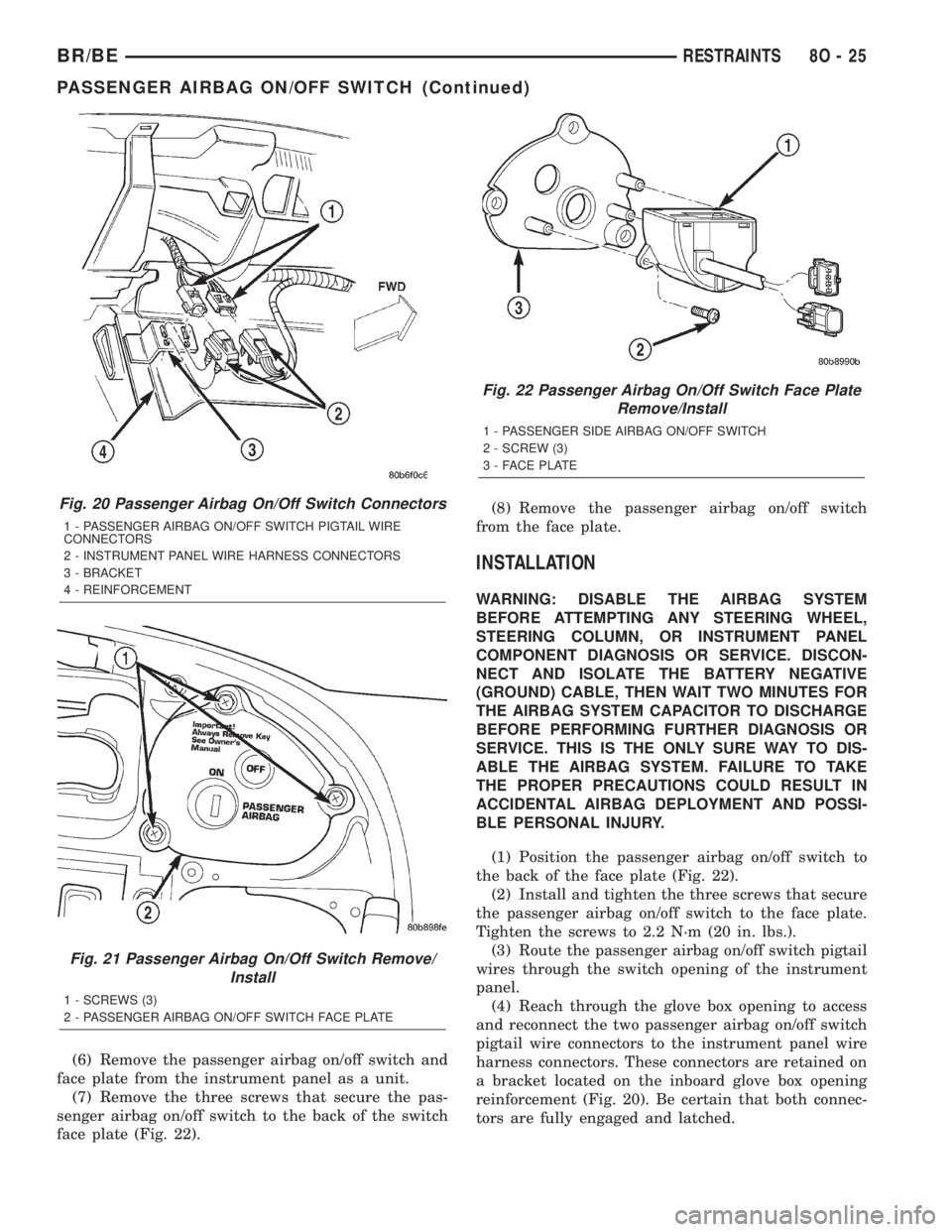
(4) Reach through the glove box opening to access
and disconnect the two passenger airbag on/off
switch pigtail wire harness connectors from the
instrument panel wire harness connectors. These
connectors are retained on a bracket located on the
inboard glove box opening reinforcement (Fig. 20).
(5) Remove the three screws that secure the pas-
senger airbag on/off switch face plate to the instru-
ment panel (Fig. 21).
8O - 24 RESTRAINTSBR/BE
PASSENGER AIRBAG ON/OFF SWITCH (Continued)
Page 700 of 2889
(6) Remove the passenger airbag on/off switch and
face plate from the instrument panel as a unit.
(7) Remove the three screws that secure the pas-
senger airbag on/off switch to the back of the switch
face plate (Fig. 22).(8) Remove the passenger airbag on/off switch
from the face plate.
INSTALLATION
WARNING: DISABLE THE AIRBAG SYSTEM
BEFORE ATTEMPTING ANY STEERING WHEEL,
STEERING COLUMN, OR INSTRUMENT PANEL
COMPONENT DIAGNOSIS OR SERVICE. DISCON-
NECT AND ISOLATE THE BATTERY NEGATIVE
(GROUND) CABLE, THEN WAIT TWO MINUTES FOR
THE AIRBAG SYSTEM CAPACITOR TO DISCHARGE
BEFORE PERFORMING FURTHER DIAGNOSIS OR
SERVICE. THIS IS THE ONLY SURE WAY TO DIS-
ABLE THE AIRBAG SYSTEM. FAILURE TO TAKE
THE PROPER PRECAUTIONS COULD RESULT IN
ACCIDENTAL AIRBAG DEPLOYMENT AND POSSI-
BLE PERSONAL INJURY.
(1) Position the passenger airbag on/off switch to
the back of the face plate (Fig. 22).
(2) Install and tighten the three screws that secure
the passenger airbag on/off switch to the face plate.
Tighten the screws to 2.2 N´m (20 in. lbs.).
(3) Route the passenger airbag on/off switch pigtail
wires through the switch opening of the instrument
panel.
(4) Reach through the glove box opening to access
and reconnect the two passenger airbag on/off switch
pigtail wire connectors to the instrument panel wire
harness connectors. These connectors are retained on
a bracket located on the inboard glove box opening
reinforcement (Fig. 20). Be certain that both connec-
tors are fully engaged and latched.
Fig. 20 Passenger Airbag On/Off Switch Connectors
1 - PASSENGER AIRBAG ON/OFF SWITCH PIGTAIL WIRE
CONNECTORS
2 - INSTRUMENT PANEL WIRE HARNESS CONNECTORS
3 - BRACKET
4 - REINFORCEMENT
Fig. 21 Passenger Airbag On/Off Switch Remove/
Install
1 - SCREWS (3)
2 - PASSENGER AIRBAG ON/OFF SWITCH FACE PLATE
Fig. 22 Passenger Airbag On/Off Switch Face Plate
Remove/Install
1 - PASSENGER SIDE AIRBAG ON/OFF SWITCH
2 - SCREW (3)
3 - FACE PLATE
BR/BERESTRAINTS 8O - 25
PASSENGER AIRBAG ON/OFF SWITCH (Continued)
Page 701 of 2889
(5) Position the passenger airbag on/off switch and
face plate unit to the opening in the instrument
panel (Fig. 21).
(6) Install and tighten the three screws that secure
the passenger airbag on/off switch face plate to the
instrument panel. Tighten the screws to 2.2 N´m (20
in. lbs.).
(7) Reinstall the glove box onto the instrument
panel. (Refer to 23 - BODY/INSTRUMENT PANEL/
GLOVE BOX - INSTALLATION).
(8) Reinstall the cluster bezel onto the instrument
panel. (Refer to 23 - BODY/INSTRUMENT PANEL/
CLUSTER BEZEL - INSTALLATION).
(9) Do not reconnect the battery negative cable at
this time. The airbag system verification test proce-
dure should be performed following service of any
airbag system component. (Refer to 8 - ELECTRI-
CAL/RESTRAINTS - STANDARD PROCEDURE -
VERIFICATION TEST).
REAR SEAT BELT &
RETRACTOR
REMOVAL
WARNING: DURING AND FOLLOWING ANY SEAT
BELT SERVICE, CAREFULLY INSPECT ALL SEAT
BELTS, BUCKLES, MOUNTING HARDWARE, AND
RETRACTORS FOR PROPER INSTALLATION,
OPERATION, OR DAMAGE. REPLACE ANY BELT
THAT IS CUT, FRAYED, OR TORN. STRAIGHTEN
ANY BELT THAT IS TWISTED. TIGHTEN ANY
LOOSE FASTENERS. REPLACE ANY BELT THAT
HAS A DAMAGED OR INOPERATIVE BUCKLE OR
RETRACTOR. REPLACE ANY BELT THAT HAS A
BENT OR DAMAGED LATCH PLATE OR ANCHOR
PLATE. NEVER ATTEMPT TO REPAIR A SEAT BELT
COMPONENT. ALWAYS REPLACE DAMAGED OR
FAULTY SEAT BELT COMPONENTS WITH THE COR-
RECT, NEW AND UNUSED REPLACEMENT PARTS
LISTED IN THE MOPAR PARTS CATALOG.
(1) Remove the rear seat from the passenger com-
partment. (Refer to 23 - BODY/SEATS/REAR SEAT -
REMOVAL).
(2) Remove the trim cover from the door sill.
(Refer to 23 - BODY/INTERIOR/DOOR SILL TRIM -
REMOVAL).
(3) Remove the screw that secures the lower seat
belt anchor plate to the quarter inner panel near the
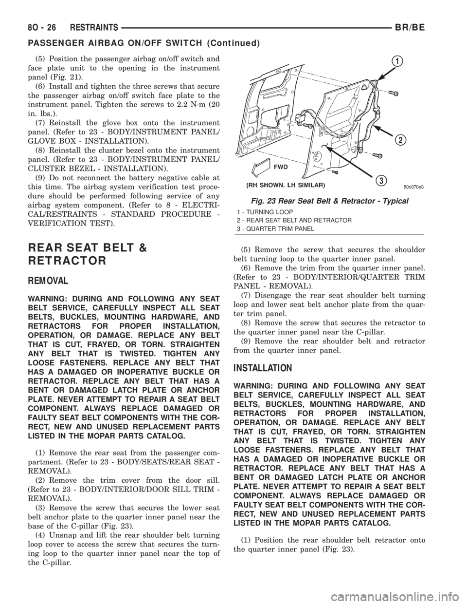
base of the C-pillar (Fig. 23).
(4) Unsnap and lift the rear shoulder belt turning
loop cover to access the screw that secures the turn-
ing loop to the quarter inner panel near the top of
the C-pillar.(5) Remove the screw that secures the shoulder
belt turning loop to the quarter inner panel.
(6) Remove the trim from the quarter inner panel.
(Refer to 23 - BODY/INTERIOR/QUARTER TRIM
PANEL - REMOVAL).
(7) Disengage the rear seat shoulder belt turning
loop and lower seat belt anchor plate from the quar-
ter trim panel.
(8) Remove the screw that secures the retractor to
the quarter inner panel near the C-pillar.
(9) Remove the rear shoulder belt and retractor
from the quarter inner panel.
INSTALLATION
WARNING: DURING AND FOLLOWING ANY SEAT
BELT SERVICE, CAREFULLY INSPECT ALL SEAT
BELTS, BUCKLES, MOUNTING HARDWARE, AND
RETRACTORS FOR PROPER INSTALLATION,
OPERATION, OR DAMAGE. REPLACE ANY BELT
THAT IS CUT, FRAYED, OR TORN. STRAIGHTEN
ANY BELT THAT IS TWISTED. TIGHTEN ANY
LOOSE FASTENERS. REPLACE ANY BELT THAT
HAS A DAMAGED OR INOPERATIVE BUCKLE OR
RETRACTOR. REPLACE ANY BELT THAT HAS A
BENT OR DAMAGED LATCH PLATE OR ANCHOR
PLATE. NEVER ATTEMPT TO REPAIR A SEAT BELT
COMPONENT. ALWAYS REPLACE DAMAGED OR
FAULTY SEAT BELT COMPONENTS WITH THE COR-
RECT, NEW AND UNUSED REPLACEMENT PARTS
LISTED IN THE MOPAR PARTS CATALOG.
(1) Position the rear shoulder belt retractor onto
the quarter inner panel (Fig. 23).
Fig. 23 Rear Seat Belt & Retractor - Typical
1 - TURNING LOOP
2 - REAR SEAT BELT AND RETRACTOR
3 - QUARTER TRIM PANEL
8O - 26 RESTRAINTSBR/BE
PASSENGER AIRBAG ON/OFF SWITCH (Continued)
Page 702 of 2889
(2) Install and tighten the screw that secures the
retractor to the quarter inner panel. Tighten the
screw to 40 N´m (29 ft. lbs.).
(3) Engage the rear seat shoulder belt turning loop
and lower seat belt anchor plate with the quarter
trim panel.
(4) Reinstall the trim onto the quarter inner panel.
(Refer to 23 - BODY/INTERIOR/QUARTER TRIM
PANEL - INSTALLATION).
(5) Position the shoulder belt turning loop onto the
quarter inner panel near the top of the C-pillar.
(6) Install and tighten the screw that secures the
shoulder belt turning loop to the quarter inner panel.
Tighten the screw to 40 N´m (29 ft. lbs.).
(7) Fold and snap the cover over the rear shoulder
belt turning loop to conceal the screw that secures
the turning loop to the quarter inner panel.
(8) Position the lower seat belt anchor plate onto
the quarter inner panel near the base of the C-pillar.
(9) Install and tighten the screw that secures the
lower seat belt anchor plate to the quarter inner
panel near the base of the C-pillar. Tighten the screw
to 40 N´m (29 ft. lbs.).
(10) Reinstall the trim cover onto the door sill.
(Refer to 23 - BODY/INTERIOR/DOOR SILL TRIM -
INSTALLATION).
(11) Reinstall the rear seat into the passenger
compartment. (Refer to 23 - BODY/SEATS/REAR
SEAT - INSTALLATION).
REAR SEAT BELT BUCKLE
REMOVAL
WARNING: DURING AND FOLLOWING ANY SEAT
BELT SERVICE, CAREFULLY INSPECT ALL SEAT
BELTS, BUCKLES, MOUNTING HARDWARE, AND
RETRACTORS FOR PROPER INSTALLATION,
OPERATION, OR DAMAGE. REPLACE ANY BELT
THAT IS CUT, FRAYED, OR TORN. STRAIGHTEN
ANY BELT THAT IS TWISTED. TIGHTEN ANY
LOOSE FASTENERS. REPLACE ANY BELT THAT
HAS A DAMAGED OR INOPERATIVE BUCKLE OR
RETRACTOR. REPLACE ANY BELT THAT HAS A
BENT OR DAMAGED LATCH PLATE OR ANCHOR
PLATE. NEVER ATTEMPT TO REPAIR A SEAT BELT
COMPONENT. ALWAYS REPLACE DAMAGED OR
FAULTY SEAT BELT COMPONENTS WITH THE COR-
RECT, NEW AND UNUSED REPLACEMENT PARTS
LISTED IN THE MOPAR PARTS CATALOG.
(1) Disengage the rear seat latch by pulling the
release handle on the underside of the rear seat
cushion.(2) Fold the rear seat unit up and back against the
cab back panel (stowed position) for access to the
rear seat belt buckle anchors.
(3) Reach through the opening between the rear
seat back and the floor panel to access and remove
the nut that secures the rear seat belt buckle/buckle
unit (right side) or lap belt/buckle unit (left side)
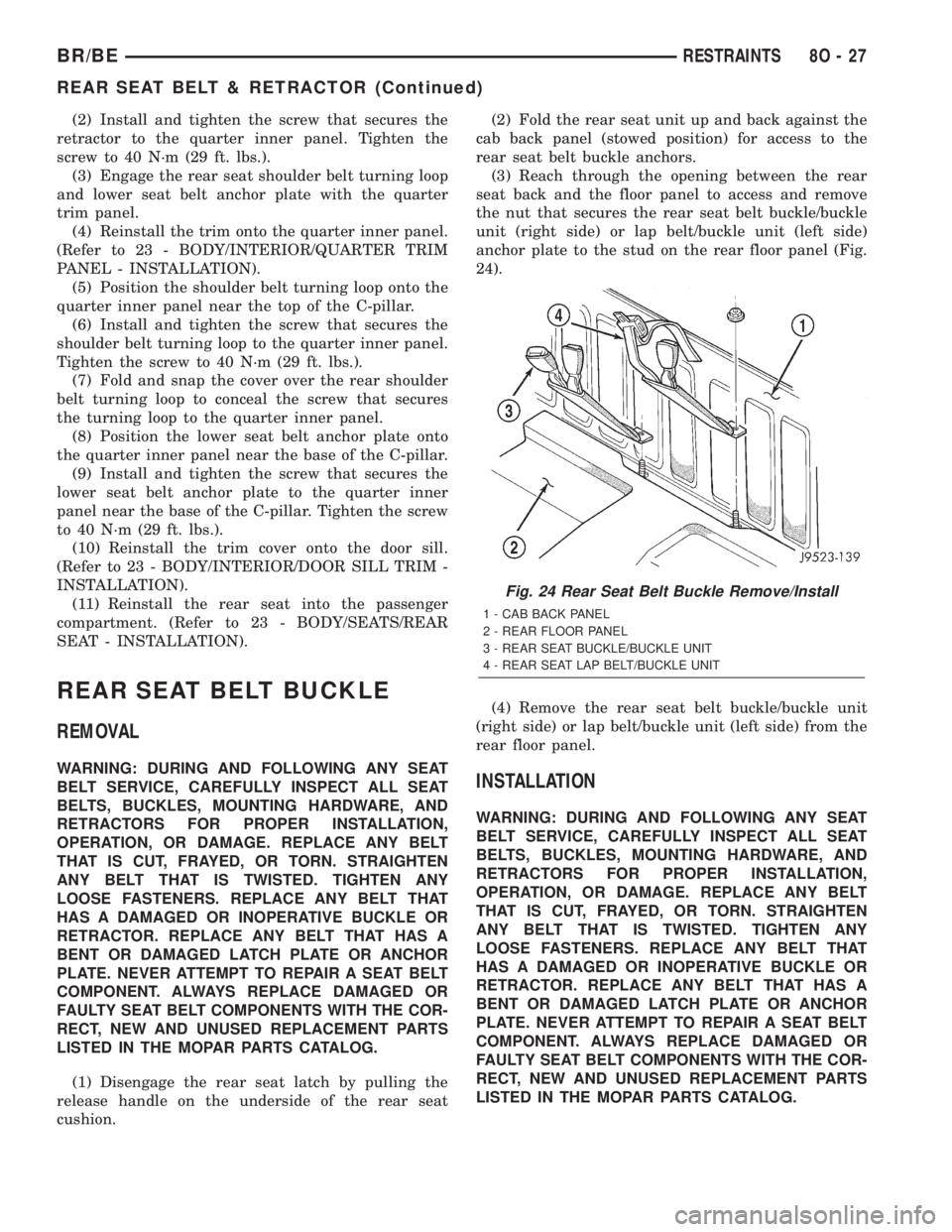
anchor plate to the stud on the rear floor panel (Fig.
24).
(4) Remove the rear seat belt buckle/buckle unit
(right side) or lap belt/buckle unit (left side) from the
rear floor panel.INSTALLATION
WARNING: DURING AND FOLLOWING ANY SEAT
BELT SERVICE, CAREFULLY INSPECT ALL SEAT
BELTS, BUCKLES, MOUNTING HARDWARE, AND
RETRACTORS FOR PROPER INSTALLATION,
OPERATION, OR DAMAGE. REPLACE ANY BELT
THAT IS CUT, FRAYED, OR TORN. STRAIGHTEN
ANY BELT THAT IS TWISTED. TIGHTEN ANY
LOOSE FASTENERS. REPLACE ANY BELT THAT
HAS A DAMAGED OR INOPERATIVE BUCKLE OR
RETRACTOR. REPLACE ANY BELT THAT HAS A
BENT OR DAMAGED LATCH PLATE OR ANCHOR
PLATE. NEVER ATTEMPT TO REPAIR A SEAT BELT
COMPONENT. ALWAYS REPLACE DAMAGED OR
FAULTY SEAT BELT COMPONENTS WITH THE COR-
RECT, NEW AND UNUSED REPLACEMENT PARTS
LISTED IN THE MOPAR PARTS CATALOG.
Fig. 24 Rear Seat Belt Buckle Remove/Install
1 - CAB BACK PANEL
2 - REAR FLOOR PANEL
3 - REAR SEAT BUCKLE/BUCKLE UNIT
4 - REAR SEAT LAP BELT/BUCKLE UNIT
BR/BERESTRAINTS 8O - 27
REAR SEAT BELT & RETRACTOR (Continued)
Page 703 of 2889
(1) Reach through the opening between the rear
seat back and the floor panel to position the rear seat
belt buckle/buckle unit (right side) or lap belt/buckle
unit (left side) onto the stud on the rear floor panel
(Fig. 24).
(2) Install and tighten the nut that secures the
rear seat belt buckle/buckle unit (right side) or lap
belt/buckle unit (left side) anchor plate to the stud on
the rear floor panel. Tighten the nut to 40 N´m (29 ft.
lbs.).
(3) Route the lap belt and buckles between the
rear seat back and rear seat cushion.
(4) Disengage the rear seat from its stowed posi-
tion by pulling the release handle on the underside of
the rear seat cushion.
(5) Fold the rear seat cushion down toward the
rear floor panel until the unit is latched in its open
position.
SEAT BELT SWITCH
DESCRIPTION
The seat belt switch is a small, normally closed,
single pole, single throw, leaf contact, momentary
switch. Only one seat belt switch is installed in the
vehicle, and it is integral to the buckle of the driver
seat belt buckle-half, located near the inboard side of
the driver side front seating position. The seat belt
switch is connected to the vehicle electrical system
through a two-wire pigtail wire and connector on the
seat belt buckle-half, which is connected to a wire
harness connector and take out of the body wire har-
ness.
The seat belt switch cannot be adjusted or repaired
and, if faulty or damaged, the entire driver seat belt
buckle-half unit must be replaced.
OPERATION
The seat belt switch is designed to control a path
to ground for the seat belt switch sense input of the
Electro-Mechanical Instrument Cluster (EMIC).
When the driver side seat belt tip-half is inserted in
the seat belt buckle, the switch opens the path to
ground; and, when the driver side seat belt tip-half is
removed from the seat belt buckle, the switch closes
the ground path. The switch is actuated by the latch
mechanism within the seat belt buckle. The EMIC
monitors the driver seat belt switch status, then con-
trols the seatbelt indicator and sends hard wired
chime requests to the Central Timer Module (CTM)
based upon that input.The seat belt switch receives ground through its
pigtail wire connection to the body wire harness from
another take out of the body wire harness. An eyelet
terminal connector on that ground take out is
secured under a nut to a ground stud on the left
lower B-pillar (standard cab models) or the left lower
cowl side inner panel (club cab and quad cab models).
The seat belt switch is connected in series between
ground and the seat belt switch sense input of the
EMIC.
DIAGNOSIS AND TESTING - SEAT BELT
SWITCH
Refer to the appropriate wiring information. The
wiring information includes wiring diagrams, proper
wire and connector repair procedures, details of wire
harness routing and retention, connector pin-out
information and location views for the various wire
harness connectors, splices and grounds.
WARNING: ON VEHICLES EQUIPPED WITH AIR-
BAGS, DISABLE THE AIRBAG SYSTEM BEFORE
ATTEMPTING ANY STEERING WHEEL, STEERING
COLUMN, OR INSTRUMENT PANEL COMPONENT
DIAGNOSIS OR SERVICE. DISCONNECT AND ISO-
LATE THE BATTERY NEGATIVE (GROUND) CABLE,
THEN WAIT TWO MINUTES FOR THE AIRBAG SYS-
TEM CAPACITOR TO DISCHARGE BEFORE PER-
FORMING FURTHER DIAGNOSIS OR SERVICE. THIS
IS THE ONLY SURE WAY TO DISABLE THE AIRBAG
SYSTEM. FAILURE TO TAKE THE PROPER PRE-
CAUTIONS COULD RESULT IN ACCIDENTAL AIR-
BAG DEPLOYMENT AND POSSIBLE PERSONAL
INJURY.
(1) Disconnect and isolate the battery negative
cable. Disconnect the body wire harness connector for
the seat belt switch from the seat belt switch pigtail
wire connector located near the floor panel under the
driver side front seat cushion. Check for continuity
between the seat belt switch sense circuit and the
ground circuit cavities in the seat belt switch pigtail
wire connector. There should be continuity with the
driver side seat belt tip-half and buckle-half unfas-
tened, and no continuity with tip-half and buckle-half
fastened. If OK, go to Step 2. If not OK, replace the
faulty driver side seat belt buckle-half unit.
(2) Check for continuity between the ground cir-
cuit cavity in the body wire harness connector for the
seat belt switch and a good ground. There should be
continuity. If OK, go to Step 3. If not OK, repair the
open ground circuit to ground (G301 - standard cab,
or G300 - club/quad cab) as required.
8O - 28 RESTRAINTSBR/BE
REAR SEAT BELT BUCKLE (Continued)
Page 704 of 2889
(3) Remove the instrument cluster from the instru-
ment panel. Check for continuity between the seat
belt switch sense circuit cavity in the instrument
panel wire harness connector (Connector C2) for the
instrument cluster and a good ground. There should
be no continuity. If OK, go to Step 4. If not OK,
repair the shorted seat belt switch sense circuit
between the seat belt switch and the instrument
cluster as required.
(4) Check for continuity between the seat belt
switch sense circuit cavities in the body wire harness
connector for the seat belt switch and the instrument
panel wire harness connector (Connector C2) for the
instrument cluster. There should be continuity. If
OK, proceed to the diagnosis for the instrument clus-
ter. (Refer to 8 - ELECTRICAL/INSTRUMENT
CLUSTER - DIAGNOSIS AND TESTING). If not OK,
repair the open seat belt switch sense circuit between
the seat belt switch and the instrument cluster as
required.
SEAT BELT TURNING LOOP
ADJUSTER
REMOVAL
WARNING: DURING AND FOLLOWING ANY SEAT
BELT SERVICE, CAREFULLY INSPECT ALL SEAT
BELTS, BUCKLES, MOUNTING HARDWARE, AND
RETRACTORS FOR PROPER INSTALLATION,
OPERATION, OR DAMAGE. REPLACE ANY BELT
THAT IS CUT, FRAYED, OR TORN. STRAIGHTEN
ANY BELT THAT IS TWISTED. TIGHTEN ANY
LOOSE FASTENERS. REPLACE ANY BELT THAT
HAS A DAMAGED OR INOPERATIVE BUCKLE OR
RETRACTOR. REPLACE ANY BELT THAT HAS A
BENT OR DAMAGED LATCH PLATE OR ANCHOR
PLATE. NEVER ATTEMPT TO REPAIR A SEAT BELT
COMPONENT. ALWAYS REPLACE DAMAGED OR
FAULTY SEAT BELT COMPONENTS WITH THE COR-
RECT, NEW AND UNUSED REPLACEMENT PARTS
LISTED IN THE MOPAR PARTS CATALOG.
(1) Remove the knob from the lever of the seat belt
turning loop adjuster. (Refer to 8 - ELECTRICAL/RE-
STRAINTS/TURNING LOOP HEIGHT ADJUSTER
KNOB - REMOVAL).
(2) Remove the screw that secures the shoulder
belt turning loop to the height adjuster.(3) Remove the trim from the B-pillar. (Refer to 23
- BODY/INTERIOR/B-PILLAR TRIM - REMOVAL).
(4) Remove the screw that secures the upper end
of the height adjuster to the B-pillar.
(5) Pull the upper end of the height adjuster away
from the B-pillar far enough to disengage the hooks
on the lower end of the adjuster from the slots in the
pillar.
(6) Remove the adjuster from the B-pillar.
INSTALLATION
WARNING: DURING AND FOLLOWING ANY SEAT
BELT SERVICE, CAREFULLY INSPECT ALL SEAT
BELTS, BUCKLES, MOUNTING HARDWARE, AND
RETRACTORS FOR PROPER INSTALLATION,
OPERATION, OR DAMAGE. REPLACE ANY BELT
THAT IS CUT, FRAYED, OR TORN. STRAIGHTEN
ANY BELT THAT IS TWISTED. TIGHTEN ANY
LOOSE FASTENERS. REPLACE ANY BELT THAT
HAS A DAMAGED OR INOPERATIVE BUCKLE OR
RETRACTOR. REPLACE ANY BELT THAT HAS A
BENT OR DAMAGED LATCH PLATE OR ANCHOR
PLATE. NEVER ATTEMPT TO REPAIR A SEAT BELT
COMPONENT. ALWAYS REPLACE DAMAGED OR
FAULTY SEAT BELT COMPONENTS WITH THE COR-
RECT, NEW AND UNUSED REPLACEMENT PARTS
LISTED IN THE MOPAR PARTS CATALOG.
(1) Position the height adjuster to the B-pillar
with the hook formations oriented toward the lower
end of the adjuster.
(2) Engage the hooks on the lower end of the
adjuster into the slots in the B-pillar.
(3) Tilt the upper end of the height adjuster up
into position against the B-pillar.
(4) Install and tighten the screw that secures the
upper end of the height adjuster to the B-pillar.
Tighten the screw to 41 N´m (30 ft. lbs.).
(5) Reinstall the trim onto the B-pillar. (Refer to
23 - BODY/INTERIOR/B-PILLAR TRIM - INSTAL-
LATION).
(6) Install and tighten the anchor screw that
secures the seat belt turning loop to the adjuster.
Tighten the screw to 30 N´m (22 ft. lbs.).
(7) Reinstall the knob onto the lever of the seat
belt turning loop adjuster. (Refer to 8 - ELECTRI-
CAL/RESTRAINTS/TURNING LOOP HEIGHT
ADJUSTER KNOB - INSTALLATION).
BR/BERESTRAINTS 8O - 29
SEAT BELT SWITCH (Continued)