2001 DODGE RAM service
[x] Cancel search: servicePage 636 of 2889
MESSAGE SYSTEMS
TABLE OF CONTENTS
page page
OVERHEAD CONSOLE
DESCRIPTION............................1
STANDARD PROCEDURE...................4
COMPASS CALIBRATION..................4
COMPASS VARIATION ADJUSTMENT........4
COMPASS DEMAGNETIZING...............5
REMOVAL...............................6
DISASSEMBLY............................7
ASSEMBLY..............................7
INSTALLATION............................8
SPECIAL TOOLS..........................8
COMPASS/MINI-TRIP COMPUTER
DESCRIPTION............................8OPERATION.............................9
DIAGNOSIS AND TESTING.................10
COMPASS MINI-TRIP COMPUTER..........10
REMOVAL..............................11
INSTALLATION...........................11
AMBIENT TEMP SENSOR
DESCRIPTION...........................11
OPERATION.............................11
DIAGNOSIS AND TESTING.................12
AMBIENT TEMPERATURE SENSOR........12
REMOVAL..............................12
INSTALLATION...........................13
OVERHEAD CONSOLE
DESCRIPTION
Two different overhead console units are available
factory-installed options on this model, base or pre-
mium. The base overhead console unit features a
garage door opener storage bin, a sunglasses storage
bin and two reading and courtesy lamps. The pre-
mium overhead console has all of the features of the
base unit, but adds a compass mini-trip computer.
See the owner's manual in the vehicle glove box for
more information on the features, use and operation
of all of the overhead console components and sys-
tems. Refer toOverhead Consolein the Contents of
Wiring Diagrams for complete circuit diagrams.
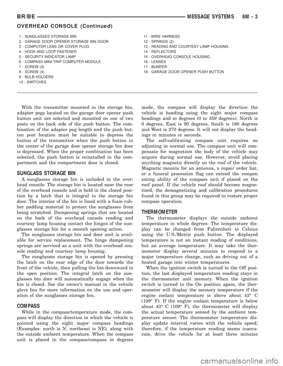
The premium overhead console (Fig. 1) includes
two front-mounted reading and courtesy lamps, a
garage door opener storage bin, and a sunglasses
storage bin. The premium overhead console includes
a compass mini-trip computer. The base overhead
console uses the same overhead console housing, but
has a computer cover plug installed in place of the
compass mini-trip computer display module lens and
push buttons.
The rear of the overhead console is secured to two
rear mounting holes in the inner roof panel by two
plastic hook formations that are integral to the over-
head console housing. The front of the overhead con-
sole is secured to the two front mounting holes of the
inner roof panel by two plastic latches that are inte-
gral to the overhead console housing. A single electri-
cal connection joins the overhead console wireharness to the roof wire harness for both the base
and premium overhead console units.
Following are general descriptions of the major
components used in the overhead console. See the
owner's manual in the vehicle glove box for more
information on the use and operation of the various
overhead console features.
GARAGE DOOR OPENER STORAGE BIN
A compartment near the front of the overhead con-
sole is designed to hold most garage door opener
remote control transmitters. The transmitter is
mounted within the compartment with an adhesive-
backed hook and loop fastener patch and, when the
compartment is closed, a push button in the center of
the compartment door is depressed to actuate the
transmitter.
A transmitter mounting kit including the adhesive-
backed hook and loop fastener material is available
for service. The garage door opener storage bin door
and the push button with three assorted length
adapter pegs are also available for service replace-
ment.
The garage door opener storage compartment door
is opened by pressing the integral latch towards the
front of the vehicle. When the compartment door is
opened, the push button unit is removed from the
compartment by squeezing the latch tabs and pulling
the unit downward. With the push button removed,
the garage door opener can be installed in the com-
partment using the adhesive-backed hook and loop
fastener material provided.
BR/BEMESSAGE SYSTEMS 8M - 1
Page 638 of 2889
With the transmitter mounted in the storage bin,
adapter pegs located on the garage door opener push
button unit are selected and mounted on one of two
posts on the back side of the push button. The com-
bination of the adapter peg length and the push but-
ton post location must be suitable to depress the
button of the transmitter when the push button in
the center of the garage door opener storage bin door
is depressed. When the proper combination has been
selected, the push button is reinstalled in the com-
partment and the compartment door is closed.
SUNGLASS STORAGE BIN
A sunglasses storage bin is included in the over-
head console. The storage bin is located near the rear
of the overhead console and is held in the closed posi-
tion by a latch that is integral to the storage bin
door. The interior of the bin is lined with a foam rub-
ber padding material to protect the sunglasses from
being scratched. Dampening springs that are located
on the back of the overhead console reading and
courtesy lamp housing contact the hinges of the sun-
glasses storage bin for a smooth opening action.
The sunglasses storage bin and door unit is avail-
able for service replacement. The hinge dampening
springs are serviced as a unit with the overhead con-
sole reading and courtesy lamp housing.
The sunglasses storage bin is opened by pressing
the latch on the rear edge of the door towards the
front of the vehicle, then pulling the bin downward to
the open position. The integral latch on the sun-
glasses bin door will automatically engage when the
bin is closed. See the owner's manual in the vehicle
glove box for more information on the use and oper-
ation of the sunglasses storage bin.
COMPASS
While in the compass/temperature mode, the com-
pass will display the direction in which the vehicle is
pointed using the eight major compass headings
(Examples: north is N, northeast is NE), along with
the outside ambient temperature. When the compass
unit is placed in the compass/compass in degreesmode, the compass will display the direction the
vehicle is heading using the eight major compass
headings and in degrees (0 to 359 degrees). North is
0 degrees, East is 90 degrees, South is 180 degrees
and West is 270 degrees. It will not display the head-
ings in minutes or seconds.
The self-calibrating compass unit requires no
adjusting in normal use. The compass unit will com-
pensate for magnetism the body of the vehicle may
acquire during normal use. However, avoid placing
anything magnetic directly on the roof of the vehicle.
Magnetic mounts for an antenna, a repair order hat,
or a funeral procession flag can exceed the compen
sating ability of the compass unit if placed on the
roof panel. If the vehicle roof should become magne-
tized, the demagnetizing and calibration procedures
found in this group may be required to restore proper
compass operation.
THERMOMETER
The thermometer displays the outside ambient
temperature in whole degrees. The temperature dis-
play can be changed from Fahrenheit to Celsius
using the U.S./Metric push button. The displayed
temperature is not an instant reading of conditions,
but an average temperature. It may take the ther-
mometer display several minutes to respond to a
major temperature change, such as driving out of a
heated garage into winter temperatures.
When the ignition switch is turned to the Off posi-
tion, the last displayed temperature reading stays in
the thermometer unit memory. When the ignition
switch is turned to the On position again, the ther-
mometer will display the memory temperature if the
engine coolant temperature is above about 43É C
(109É F). If the engine coolant temperature is below
about 43É C (109É F), the thermometer will display
the actual temperature sensed by the ambient tem-
perature sensor. The thermometer temperature dis-
play update interval varies with the vehicle speed;
therefore, if the temperature reading seems inaccu-
rate, drive the vehicle for at least three minutes
1 - SUNGLASSES STORAGE BIN
2 - GARAGE DOOR OPENER STORAGE BIN DOOR
3 - COMPUTER LENS OR COVER PLUG
4 - HOOK AND LOOP FASTENER
5 - SECURITY INDICATOR LAMP
6 - COMPASS MINI-TRIP COMPUTER MODULE
7 - SCREW (3)
8 - SCREW (4)
9 - BULB HOLDERS
10 - SWITCHES11 - WIRE HARNESS
12 - SPRINGS (2)
13 - READING AND COURTESY LAMP HOUSING
14 - REFLECTORS
15 - OVERHEAD CONSOLE HOUSING
16 - LENSES
17 - BUMPER
18 - GARAGE DOOR OPENER PUSH BUTTON
BR/BEMESSAGE SYSTEMS 8M - 3
OVERHEAD CONSOLE (Continued)
Page 639 of 2889
while maintaining a speed of 48 kilometers-per-hour
(30 miles-per-hour) or higher.
The thermometer function is supported by an
ambient temperature sensor. The sensor is mounted
outside the passenger compartment near the front
and center of the vehicle, and is hard wired to the
module. The ambient temperature sensor is available
as a separate service item.
STANDARD PROCEDURE - COMPASS
CALIBRATION
CAUTION: Do not place any external magnets, such
as magnetic roof mount antennas, in the vicinity of
the compass. Do not use magnetic tools when ser-
vicing the overhead console.
The electronic compass unit features a self-cali-
brating design, which simplifies the calibration pro-
cedure. This feature automatically updates the
compass calibration while the vehicle is being driven.
This allows the compass unit to compensate for small
changes in the residual magnetism that the vehicle
may acquire during normal use. If the compass read-
ings appear to be erratic or out of calibration, per-
form the following calibration procedure. Also, new
service replacement compass mini-trip computer
modules must have their compass calibrated using
this procedure. Do not attempt to calibrate the com-
pass near large metal objects such as other vehicles,
large buildings, or bridges; or, near overhead or
underground power lines.
(1) Start the engine. If the compass/temperature
data is not currently being displayed, momentarily
depress and release the Step push button to step
through the display options until you have reached
the compass/temperature display.
(2) Depress both the U.S./Metric and the Step
push buttons at the same time for more than six sec-
onds, until ªCALº appears in the display, then release
both push buttons. The ªCALº in the display indi-
cates that the compass is in the calibration mode.
(3) Drive the vehicle on a level surface, at least
fifty feet away from large metal objects and power
lines, in all four compass directions, such as driving
around a city block several times or driving in two to
three complete circles at a slow to medium speed.
(4) When the calibration is successfully completed,
ªCALº will disappear from the display and normal
compass mini-trip computer operation will resume.
NOTE: If the ªCALº message remains in the display,
either there is excessive magnetism near the com-
pass, or the unit is faulty. Repeat the calibration
procedure at least one more time.NOTE: If the wrong direction is still indicated in the
compass display, the area selected for calibration
may be too close to a strong magnetic field. Repeat
the calibration procedure in another location.
STANDARD PROCEDURE - COMPASS
VARIATION ADJUSTMENT
Compass variance, also known as magnetic decli-
nation, is the difference in angle between magnetic
north and true geographic north. In some geographic
locations, the difference between magnetic and geo-
graphic north is great enough to cause the compass
to give false readings. If this problem occurs, the
compass variance must be set. There are two meth-
ods that can be used to enter this information into
the compass mini-trip computer module. They are
the zone method and the direct method.
ZONE METHOD
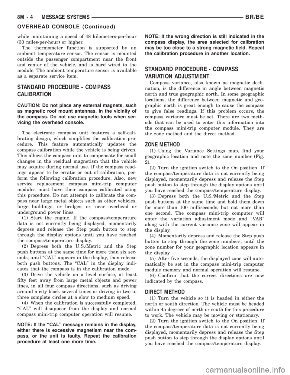
(1) Using the Variance Settings map, find your
geographic location and note the zone number (Fig.
2).
(2) Turn the ignition switch to the On position. If
the compass/temperature data is not currently being
displayed, momentarily depress and release the Step
push button to step through the display options until
you have reached the compass/temperature display.
(3) Depress both the U.S./Metric and the Step
push buttons at the same time and hold them down
for more than 100 milliseconds, but not more than
one second. The compass mini-trip computer will
enter the variation adjustment mode and ªVARº
along with the current variance zone will appear in
the display.
(4) Momentarily depress and release the Step push
button to step through the zone numbers, until the
zone number for your geographic location appears in
the display.
(5) After five seconds, the displayed zone will auto-
matically be set in the compass mini-trip computer
module memory and normal operation will resume.
(6) Confirm that the correct directions are now
indicated by the compass.
DIRECT METHOD
(1) Turn the vehicle so it is headed in either the
north or south direction. The vehicle must be headed
within 45 degrees of north or south for this procedure
to work. The vehicle may be moving or stationary.
(2) Turn the ignition switch to the On position. If
the compass/temperature data is not currently being
displayed, momentarily depress and release the Step
push button to step through the display options until
you have reached the compass/temperature display.
8M - 4 MESSAGE SYSTEMSBR/BE
OVERHEAD CONSOLE (Continued)
Page 644 of 2889
Compass mini-trip computer units for vehicles
equipped with the VTSS include a red Light-Emit-
ting Diode (LED) on their electronic circuit board.
This LED protrudes through the bottom of the lens
on the front of the overhead console unit, and serves
as the security indicator lamp. Refer toSecurity
Indicator Lampin Vehicle Theft/Security Systems
for more information on this feature.
The compass mini-trip computer module contains a
central processing unit and interfaces with other
electronic modules in the vehicle on the Chrysler Col-
lision Detection (CCD) data bus network. The CCD
data bus network allows the sharing of sensor infor-
mation. This helps to reduce wire harness complexity,
reduce internal controller hardware, and reduce com-
ponent sensor current loads. At the same time, this
system provides increased reliability, enhanced diag-
nostics, and allows the addition of many new feature
capabilities.
The compass mini-trip computer provides several
electronic functions and features. Some of the func-
tions and features that the compass mini-trip com-
puter module supports and/or controls, include the
following display options:
²Compass and temperature- provides the out-
side temperature and one of eight compass readings
to indicate the direction the vehicle is facing.
²Compass and compass in degrees- provides
one of eight compass readings to indicate the direc-
tion the vehicle is facing and provides the compass
direction in degrees.
²Trip odometer (ODO)- shows the distance
travelled since the last trip computer reset.
²Average fuel economy (AVG ECO)- shows
the average fuel economy since the last trip computer
reset.
²Instant fuel economy (ECO)- shows the
present fuel economy based upon the current vehicle
distance and fuel used information.
²Distance to empty (DTE)- shows the esti-
mated distance that can be travelled with the fuel
remaining in the fuel tank. This estimated distance
is computed using the average miles-per-gallon from
the last 30 gallons of fuel used.
²Elapsed time (ET)- shows the accumulated
ignition-on time since the last trip computer reset.
²Blank screen- the compass mini-trip VFD is
turned off.
The ambient temperature sensor is hard wired to
the compass mini-trip computer module. Data input
for all other compass mini-trip computer functions,
including VFD dimming level, is received through
CCD data bus messages. The compass mini-trip com-
puter uses its internal programming and all of these
inputs to calculate and display the requested data. If
the data displayed is incorrect, perform the self-diag-nostic tests as described in this group. If these tests
prove inconclusive, the use of a DRBIIItscan tool
and the proper Diagnostic Procedures manual are
recommended for further testing of the compass
mini-trip computer module and the CCD data bus.
The compass mini-trip computer module cannot be
repaired, and is available for service only as a unit. If
faulty or damaged, the complete module must be
replaced.
OPERATION
The compass mini-trip computer only operates with
the ignition switch in the On position. When the igni-
tion switch is turned to the On position, all of the
segments in the compass mini-trip computer VFD
will be turned on for one second, then the display
will return to the last function being displayed before
the ignition was turned to the Off position. With the
ignition switch in the On position, momentarily
depressing and releasing the Step push button switch
will cause the compass-mini-trip computer to change
its mode of operation, and momentarily depressing
and releasing the U.S./Metric push button will cause
the unit to toggle between U.S. and Metric measure-
ments. While in either compass mode, depressing the
U.S./Metric push button for more than ten seconds
will toggle the display between the compass/temper-
ature and the compass/compass in degrees modes.
This compass mini-trip computer features several
functions that can be reset. If both the Step and U.S./
Metric push buttons are depressed at the same time
with the ignition switch in the On position, the trip
computer information that can be reset is reset.
Depressing and releasing the Step and U.S./Metric
push buttons at the same time for more than 100
milliseconds, but not more than one second while in
any display mode (except the compass/temperature
mode) will cause a local reset. A local reset affects
only the function currently displayed. See the Reset
Chart below for more information on this feature.
Performing a local reset while in the compass/tem-
perature mode enters the module into the compass
variance setting mode.
Depressing and releasing the Step and U.S./Metric
push buttons at the same time for more than two
seconds while in any display mode (except the com-
pass/temperature mode) will cause a global reset. A
global reset changes all of the trip computer func-
tions that can be reset.
For more information on the features and control
functions of the compass mini-trip computer, see the
owner's manual in the vehicle glove box.
BR/BEMESSAGE SYSTEMS 8M - 9
COMPASS/MINI-TRIP COMPUTER (Continued)
Page 646 of 2889

NOTE: If the compass functions, but accuracy is
suspect, it may be necessary to perform a variation
adjustment. This procedure allows the compass
unit to accommodate variations in the earth's mag-
netic field strength, based on geographic location.
Refer to Compass Variation Adjustment in the Ser-
vice Procedures section of this group.
NOTE: If the compass reading has blanked out, and
only ªCALº appears in the display, demagnetizing
may be necessary to remove excessive residual
magnetic fields from the vehicle. Refer to Compass
Demagnetizing in the Service Procedures section of
this group.
REMOVAL
(1) Disconnect and isolate the battery negative
cable.
(2) Remove the overhead console from the head-
liner. Refer toOverhead Consolein the Removal
and Installation section of this group for the proce-
dures.
(3) Remove the three screws that secure the com-
pass mini-trip computer module to the overhead con-
sole housing (Fig. 7).
(4) Pull the compass mini-trip computer module
away from the overhead console far enough to access
the wire harness connector.
(5) Disconnect the overhead console wire harness
connector from the compass mini-trip computer mod-
ule connector receptacle.
(6) Remove the compass mini-trip computer mod-
ule from the overhead console housing.
INSTALLATION
(1) Position the compass mini-trip computer mod-
ule onto the overhead console housing.
(2) Reconnect the overhead console wire harness
connector to the compass mini-trip computer module
connector receptacle.
(3) Install and tighten the three screws that secure
the compass mini-trip computer module to the over-
head console housing. Tighten the screws to 2.2 N´m
(20 in. lbs.).
(4) Install the overhead console onto the headliner.
Refer toOverhead Consolein the Removal and
Installation section of this group for the procedures.
(5) Reconnect the battery negative cable.
NOTE: If a new compass mini-trip computer has
been installed, the compass will have to be cali-
brated and the variance set. Refer to Compass Vari-
ation Adjustment and Compass Calibration in the
Service Procedures section of this group for the
procedures.
AMBIENT TEMP SENSOR
DESCRIPTION
Ambient air temperature is monitored by the com-
pass mini-trip computer module through the ambient
temperature sensor. The ambient temperature sensor
is a variable resistor mounted to a bracket that is
secured with a screw to the underside of the hood
panel near the hood latch striker in the engine com-
partment.
For complete circuit diagrams, refer toOverhead
Consolein the Contents of Wiring Diagrams. The
ambient temperature sensor cannot be adjusted or
repaired and, if faulty or damaged, it must be
replaced.
OPERATION
The ambient temperature sensor is a variable
resistor that operates on a five-volt reference signal
sent to it by the compass mini-trip computer module.
The resistance in the sensor changes as temperature
changes, changing the return circuit voltage to the
compass mini-trip computer module. Based upon the
resistance in the sensor, the compass mini-trip com-
puter module senses a specific voltage on the return
circuit, which it is programmed to correspond to a
specific temperature.Fig. 7 Compass Mini-Trip Computer
1 - WIRE HARNESS CONNECTOR
2 - SCREWS (3)
3 - COMPASS MINI-TRIP COMPUTER MODULE
4 - FRONT LATCHES
BR/BEMESSAGE SYSTEMS 8M - 11
COMPASS/MINI-TRIP COMPUTER (Continued)
Page 650 of 2889
POWER SYSTEMS
TABLE OF CONTENTS
page page
POWER LOCKS............................ 1
POWER MIRRORS........................ 10POWER SEAT SYSTEM..................... 15
POWER WINDOWS........................ 23
POWER LOCKS
TABLE OF CONTENTS
page page
POWER LOCKS
DESCRIPTION............................1
OPERATION.............................3
DIAGNOSIS AND TESTING..................4
POWER LOCK SYSTEM...................4
POWER LOCK & REMOTE KEYLESS
ENTRY SYSTEM.........................4
DOOR CYLINDER LOCK SWITCH
DESCRIPTION............................5
OPERATION.............................5
DIAGNOSIS AND TESTING..................5
DOOR CYLINDER LOCK SWITCH...........5
REMOVAL...............................6
INSTALLATION............................6
POWER LOCK MOTOR
DESCRIPTION............................6OPERATION.............................6
DIAGNOSIS AND TESTING..................7
POWER LOCK MOTOR...................7
REMOTE KEYLESS ENTRY TRANSMITTER
DESCRIPTION............................7
OPERATION.............................7
DIAGNOSIS AND TESTING..................7
REMOTE KEYLESS ENTRY TRANSMITTER....7
STANDARD PROCEDURE...................8
RKE TRANSMITTER PROGRAMMING........8
RKE TRANSMITTER BATTERIES............8
POWER LOCK SWITCH
DESCRIPTION............................8
OPERATION.............................8
DIAGNOSIS AND TESTING..................8
POWER LOCK SWITCH...................8
POWER LOCKS
DESCRIPTION - POWER LOCK SYSTEM
Two different power lock systems are offered as
optional factory-installed equipment on this model.
Both power lock systems are offered only on models
that are also equipped with power windows. On mod-
els without the optional Remote Keyless Entry (RKE)
system, a base version of the Central Timer Module
(CTM) is used. In this version of the power lock sys-
tem, the power lock switches provide the only control
over the operation of the power lock motors. On mod-
els with the optional RKE system, a high-line or pre-
mium version of the CTM is used to provide many
electronic features and conveniences that are not pos-
sible with the base version CTM. In this power lock
system, the power lock motors are controlled by the
microprocessor-based high-line or premium version ofthe CTM based upon the CTM programming and
electronic message inputs received from other elec-
tronic modules in the vehicle over the Chrysler Col-
lision Detection (CCD) data bus network, Radio
Frequency (RF) inputs received from the RKE trans-
mitters, as well as many hard wired inputs.
Both versions of the power lock system include the
following major components, which are described in
further detail elsewhere in this service manual:
²Power Lock Motors- A reversible electric
motor integral to the door latch of each front door
locks or unlocks the front door latch when provided
with the appropriate electrical inputs.
²Power Lock Switches- A power lock switch
integral to the power window/lock switch unit located
near the forward end of the arm rest on each front
door trim panel allows the power door lock system to
be operated by either the driver or the front seat pas-
senger.
BR/BEPOWER SYSTEMS 8N - 1
Page 651 of 2889
On those models equipped with the optional RKE
system, the power lock system also includes the fol-
lowing components, which are described in further
detail elsewhere in this service manual:
²Central Timer Module- The high-line or pre-
mium Central Timer Module (CTM) is located under
the driver side end of the instrument panel, inboard
of the instrument panel steering column opening.
The high-line or premium CTM contains a micropro-
cessor and software that allow it to provide the many
electronic functions and features not available with
base version of the power lock system.
²Door Cylinder Lock Switches- A resistor-
multiplexed switch located on the back of each front
door lock cylinder allows the power door lock system
to be operated using a key inserted in either the
driver or passenger front door lock cylinder.
Some of the additional features of the power lock
system found in vehicles with the RKE system option
include:
²Automatic Door Lock- The high-line/premium
CTM provides an optional automatic door lock fea-
ture (also known as rolling door locks). This is a pro-
grammable feature.
²Central Locking- The high-line/premium CTM
provides an optional central locking/unlocking fea-
ture.
²Door Lock Inhibit- The high-line/premium
CTM provides a door lock inhibit feature.
²Enhanced Accident Response- The high-line/
premium CTM provides an optional enhanced acci-
dent response feature. This is a programmable
feature.
Hard wired circuitry connects the power lock sys-
tem components to the electrical system of the vehi-
cle. These hard wired circuits are integral to several
wire harnesses, which are routed throughout the
vehicle and retained by many different methods.
These circuits may be connected to each other, to the
vehicle electrical system and to the power lock sys-
tem components through the use of a combination of
soldered splices, splice block connectors, and many
different types of wire harness terminal connectors
and insulators. Refer to the appropriate wiring infor-
mation. The wiring information includes wiring dia-
grams, proper wire and connector repair procedures,
further details on wire harness routing and reten-
tion, as well as pin-out and location views for the
various wire harness connectors, splices and grounds.
Many of the electronic features in the vehicle con-
trolled or supported by the high-line or premium ver-
sions of the CTM are programmable using the
DRBIIItscan tool. In addition, the high-line/pre-
mium CTM software is Flash compatible, which
means it can be reprogrammed using Flash repro-
gramming procedures. However, if any of the CTMhardware components are damaged or faulty, the
entire CTM unit must be replaced. The power lock
system components and the hard wired inputs or out-
puts of the CTM can be diagnosed using conventional
diagnostic tools and methods; however, for diagnosis
of the high-line or premium versions of the CTM or
the CCD data bus, the use of a DRBIIItscan tool is
required. Refer to the appropriate diagnostic infor-
mation.
DESCRIPTION - REMOTE KEYLESS ENTRY
SYSTEM
A Remote Keyless Entry (RKE) system is an avail-
able option on this model. The Remote Keyless Entry
(RKE) system is a Radio Frequency (RF) system that
allows the remote operation of the power lock system
and, if the vehicle is so equipped, the Vehicle Theft
Security System (VTSS). (Refer to 8 - ELECTRICAL/
VEHICLE THEFT SECURITY - DESCRIPTION).
The RKE system includes the following major compo-
nents, which are described in further detail else-
where in this service manual:
²Central Timer Module- The high-line or pre-
mium Central Timer Module (CTM) is located under
the driver side end of the instrument panel, inboard
of the instrument panel steering column opening.
The high-line or premium CTM contains a micropro-
cessor, an RF receiver, and the software that allow it
to provide the many electronic functions and features
of the RKE system.
²Keyless Entry Transmitter- The keyless
entry transmitter is a small, battery-powered, RF
transmitter that is contained within a molded plastic
case that is designed to also serve as a convenient
key fob.
Some additional features of the RKE system
include:
²Horn Chirp- This feature provides a short,
sharp chirp of the vehicle horn to give an audible
confirmation that a valid Lock signal has been
received from the RKE transmitter. This feature can
be enabled or disabled and, if enabled, one of two
optional horn chirp durations (twenty or forty milli-
seconds) can also be selected.
²Illuminated Entry- This feature turns on the
courtesy lamps in the vehicle for a timed interval
(about thirty seconds) each time a valid Unlock sig-
nal has been received from the RKE transmitter.
²Panic Mode- This feature allows the vehicle
operator to cause the vehicle horn to pulse, the head-
lights to flash, and the courtesy lamps to illuminate
for about three minutes by depressing a Panic button
on the RKE transmitter. Pressing the Panic button a
second time will cancel the Panic mode. A vehicle
speed of about 24 kilometers-per-hour (15 miles-per-
hour) will also cancel the panic mode.
8N - 2 POWER LOCKSBR/BE
POWER LOCKS (Continued)
Page 661 of 2889
REMOVAL
(1) Disconnect and isolate the battery negative
cable.
(2) Unplug the wire harness connector from the
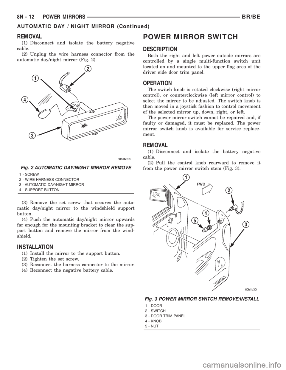
automatic day/night mirror (Fig. 2).
(3) Remove the set screw that secures the auto-
matic day/night mirror to the windshield support
button.
(4) Push the automatic day/night mirror upwards
far enough for the mounting bracket to clear the sup-
port button and remove the mirror from the wind-
shield.
INSTALLATION
(1) Install the mirror to the support button.
(2) Tighten the set screw.
(3) Reconnect the harness connector to the mirror.
(4) Reconnect the negative battery cable.
POWER MIRROR SWITCH
DESCRIPTION
Both the right and left power outside mirrors are
controlled by a single multi-function switch unit
located on and mounted to the upper flag area of the
driver side door trim panel.
OPERATION
The switch knob is rotated clockwise (right mirror
control), or counterclockwise (left mirror control) to
select the mirror to be adjusted. The switch knob is
then moved in a joystick fashion to control movement
of the selected mirror up, down, right, or left.
The power mirror switch cannot be repaired and, if
faulty or damaged, it must be replaced. The power
mirror switch knob is available for service replace-
ment.
REMOVAL
(1) Disconnect and isolate the battery negative
cable.
(2) Pull the control knob rearward to remove it
from the power mirror switch stem (Fig. 3).
Fig. 2 AUTOMATIC DAY/NIGHT MIRROR REMOVE
1 - SCREW
2 - WIRE HARNESS CONNECTOR
3 - AUTOMATIC DAY/NIGHT MIRROR
4 - SUPPORT BUTTON
Fig. 3 POWER MIRROR SWITCH REMOVE/INSTALL
1 - DOOR
2 - SWITCH
3 - DOOR TRIM PANEL
4 - KNOB
5 - NUT
8N - 12 POWER MIRRORSBR/BE
AUTOMATIC DAY / NIGHT MIRROR (Continued)