2001 DODGE RAM service
[x] Cancel search: servicePage 616 of 2889
(1) Disconnect and isolate the battery negative
cable. Remove the headlamp switch from the instru-
ment panel. (Refer to 8 - ELECTRICAL/LAMPS/
LIGHTING - EXTERIOR/HEADLAMP SWITCH -
REMOVAL) for the procedures. Unplug the headlamp
switch wire harness connectors. Check for continuity
between the left door jamb switch sense circuit cavity
of the headlamp switch wire harness connector and a
good ground. There should be continuity with the
driver door open, and no continuity with the driver
door closed. If OK, go to Step 2. If not OK, repair the
circuit to the driver door jamb switch as required.
(2) Remove the Central Timer Module (CTM) from
its mounting bracket to access the CTM wire harness
connectors. (Refer to 8 - ELECTRICAL/ELEC-
TRONIC CONTROL MODULES/BODY CONTROL/
CENTRAL TIMER MODUL - REMOVAL) for the
procedures. Unplug the 14-way CTM wire harness
connector. Remove the key from the ignition lock cyl-
inder. Check for continuity between the key-in igni-
tion switch sense circuit cavity of the 14-way CTM
wire harness connector and a good ground. There
should be no continuity. If OK, go to Step 3. If not
OK, repair the short circuit as required.
(3) Check for continuity between the key-in igni-
tion switch sense circuit cavities of the 14-way CTM
wire harness connector and the headlamp switch
wire harness connector. There should be continuity. If
OK, go to Step 4. If not OK, repair the open circuit
as required.
(4) Check for continuity between the left front door
jamb switch sense circuit terminal and the key-in
ignition switch sense circuit terminal of the head-
lamp switch. There should be no continuity with the
switch in the Off position, and continuity with the
switch in the park or head lamps On position. If
OK,(Refer to 8 - ELECTRICAL/ELECTRONIC CON-
TROL MODULES/BODY CONTROL/CENTRAL
TIMER MODUL - DIAGNOSIS AND TESTING) If
not OK, replace the faulty headlamp switch.
REMOVAL
WARNING: ON VEHICLES EQUIPPED WITH AIR-
BAGS, DISABLE THE AIRBAG SYSTEM BEFORE
ATTEMPTING ANY STEERING WHEEL, STEERING
COLUMN, OR INSTRUMENT PANEL COMPONENT
DIAGNOSIS OR SERVICE. DISCONNECT AND ISO-
LATE THE BATTERY NEGATIVE (GROUND) CABLE,
THEN WAIT TWO MINUTES FOR THE AIRBAG SYS-
TEM CAPACITOR TO DISCHARGE BEFORE PER-
FORMING FURTHER DIAGNOSIS OR SERVICE. THIS
IS THE ONLY SURE WAY TO DISABLE THE AIRBAG
SYSTEM. FAILURE TO TAKE THE PROPER PRE-
CAUTIONS COULD RESULT IN ACCIDENTAL AIR-BAG DEPLOYMENT AND POSSIBLE PERSONAL
INJURY.
(1) Disconnect and isolate the battery negative
cable.
(2) Remove the cluster bezel from the instrument
panel. (Refer to 23 - BODY/INSTRUMENT PANEL/
CLUSTER BEZEL - REMOVAL).
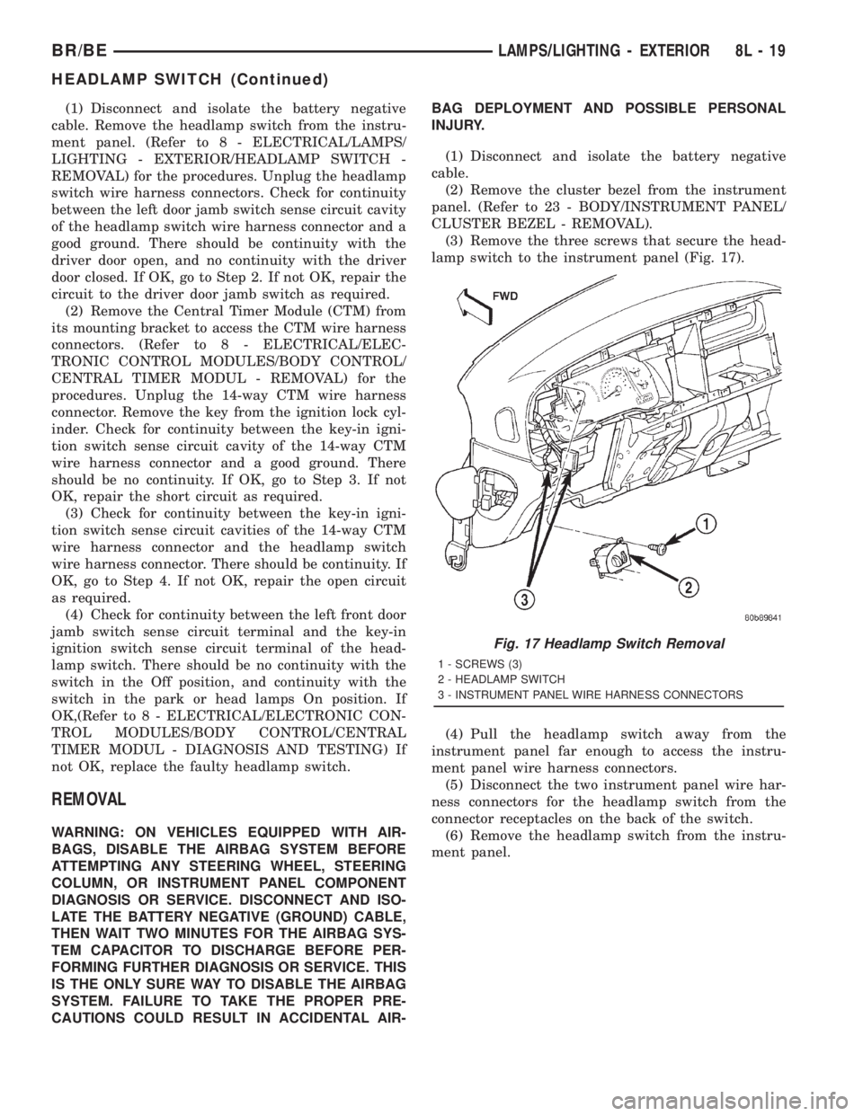
(3) Remove the three screws that secure the head-
lamp switch to the instrument panel (Fig. 17).
(4) Pull the headlamp switch away from the
instrument panel far enough to access the instru-
ment panel wire harness connectors.
(5) Disconnect the two instrument panel wire har-
ness connectors for the headlamp switch from the
connector receptacles on the back of the switch.
(6) Remove the headlamp switch from the instru-
ment panel.
Fig. 17 Headlamp Switch Removal
1 - SCREWS (3)
2 - HEADLAMP SWITCH
3 - INSTRUMENT PANEL WIRE HARNESS CONNECTORS
BR/BELAMPS/LIGHTING - EXTERIOR 8L - 19
HEADLAMP SWITCH (Continued)
Page 617 of 2889
INSTALLATION
WARNING: ON VEHICLES EQUIPPED WITH AIR-
BAGS, DISABLE THE AIRBAG SYSTEM BEFORE
ATTEMPTING ANY STEERING WHEEL, STEERING
COLUMN, OR INSTRUMENT PANEL COMPONENT
DIAGNOSIS OR SERVICE. DISCONNECT AND ISO-
LATE THE BATTERY NEGATIVE (GROUND) CABLE,
THEN WAIT TWO MINUTES FOR THE AIRBAG SYS-
TEM CAPACITOR TO DISCHARGE BEFORE PER-
FORMING FURTHER DIAGNOSIS OR SERVICE. THIS
IS THE ONLY SURE WAY TO DISABLE THE AIRBAG
SYSTEM. FAILURE TO TAKE THE PROPER PRE-
CAUTIONS COULD RESULT IN ACCIDENTAL AIR-
BAG DEPLOYMENT AND POSSIBLE PERSONAL
INJURY.
(1) Position the headlamp switch to the instru-
ment panel.
(2) Reconnect the two instrument panel wire har-
ness connectors for the headlamp switch to the con-
nector receptacles on the back of the switch.
(3) Position the headlamp switch into the instru-
ment panel.
(4) Install and tighten the three screws that secure
the headlamp switch to the instrument panel.
Tighten the screws to 2.2 N´m (20 in. lbs.).
(5) Reinstall the cluster bezel onto the instrument
panel. (Refer to 23 - BODY/INSTRUMENT PANEL/
CLUSTER BEZEL - INSTALLATION).
(6) Connect the battery negative cable.
HEADLAMP UNIT
REMOVAL
(1) Disconnect and isolate the battery negative
cable.
(2) Remove push-in fastener attaching seal to radi-
ator closure panel.
(3) Remove park and turn signal lamp.
(4) Remove screws attaching top of headlamp mod-
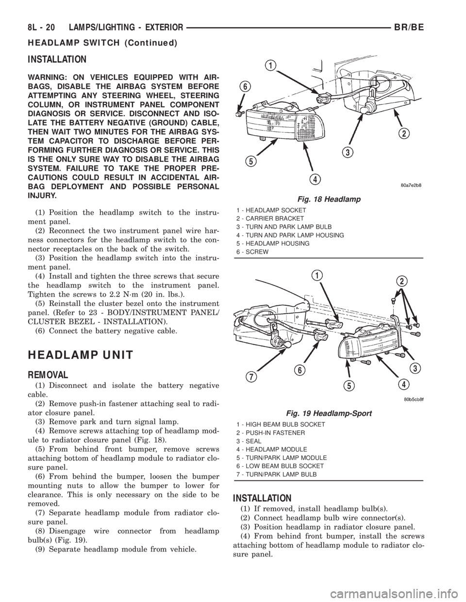
ule to radiator closure panel (Fig. 18).
(5) From behind front bumper, remove screws
attaching bottom of headlamp module to radiator clo-
sure panel.
(6) From behind the bumper, loosen the bumper
mounting nuts to allow the bumper to lower for
clearance. This is only necessary on the side to be
removed.
(7) Separate headlamp module from radiator clo-
sure panel.
(8) Disengage wire connector from headlamp
bulb(s) (Fig. 19).
(9) Separate headlamp module from vehicle.
INSTALLATION
(1) If removed, install headlamp bulb(s).
(2) Connect headlamp bulb wire connector(s).
(3) Position headlamp in radiator closure panel.
(4) From behind front bumper, install the screws
attaching bottom of headlamp module to radiator clo-
sure panel.
Fig. 18 Headlamp
1 - HEADLAMP SOCKET
2 - CARRIER BRACKET
3 - TURN AND PARK LAMP BULB
4 - TURN AND PARK LAMP HOUSING
5 - HEADLAMP HOUSING
6 - SCREW
Fig. 19 Headlamp-Sport
1 - HIGH BEAM BULB SOCKET
2 - PUSH-IN FASTENER
3 - SEAL
4 - HEADLAMP MODULE
5 - TURN/PARK LAMP MODULE
6 - LOW BEAM BULB SOCKET
7 - TURN/PARK LAMP BULB
8L - 20 LAMPS/LIGHTING - EXTERIORBR/BE
HEADLAMP SWITCH (Continued)
Page 622 of 2889
spring mechanism rotates with the steering wheel
and the cam lobes contact the cancel actuator when
it is extended from the multi-function switch. When
the steering wheel is rotated during a turning
maneuver, one of the two turn signal cancel cam
lobes will contact the turn signal cancel actuator. The
cancel actuator latches against the cancel cam rota-
tion in the direction opposite that which is signaled.
In other words, if the left turn signal detent is
selected, the lobes of the cancel cam will ratchet past
the cancel actuator when the steering wheel is
rotated to the left, but will unlatch the cancel actua-
tor as the steering wheel rotates to the right and
returns to center, which will cancel the turn signal
event and release the control stalk from the detent so
it returns to the neutral Off position.
²Washer Mode- Pushing the button on the end
of the multi-function switch control knob towards the
steering column provides a battery current output
through the momentary single pole, single throw
washer switch circuitry to operate the washer pump/
motor and provides a signal to the CTM. If the wip-
ers are not operating when the washer switch is
actuated, the CTM will operate the wiper motor for
as long as the washer switch is depressed plus about
three additional wipe cycles. If the wipers are oper-
ating in the intermittent mode when the washer
switch is actuated, the CTM will operate the wiper
motor at a fixed low speed for as long as the washer
switch is depressed plus about three additional wipe
cycles before the wipers return to the selected inter-
mittent wipe interval.DIAGNOSIS AND TESTING - MULTI-FUNCTION
SWITCH
Refer to the appropriate wiring information. The
wiring information includes wiring diagrams, proper
wire and connector repair procedures, details of wire
harness routing and retention, connector pin-out
information and location views for the various wire
harness connectors, splices and grounds.
WARNING: ON VEHICLES EQUIPPED WITH AIR-
BAGS, DISABLE THE AIRBAG SYSTEM BEFORE
ATTEMPTING ANY STEERING WHEEL, STEERING
COLUMN, OR INSTRUMENT PANEL COMPONENT
DIAGNOSIS OR SERVICE. DISCONNECT AND ISO-
LATE THE BATTERY NEGATIVE (GROUND) CABLE,
THEN WAIT TWO MINUTES FOR THE AIRBAG SYS-
TEM CAPACITOR TO DISCHARGE BEFORE PER-
FORMING FURTHER DIAGNOSIS OR SERVICE. THIS
IS THE ONLY SURE WAY TO DISABLE THE AIRBAG
SYSTEM. FAILURE TO TAKE THE PROPER PRE-
CAUTIONS COULD RESULT IN ACCIDENTAL AIR-
BAG DEPLOYMENT AND POSSIBLE PERSONAL
INJURY.
(1) Disconnect and isolate the battery negative
cable. Disconnect the instrument panel wire harness
connector from the multi-function switch connector
receptacle.
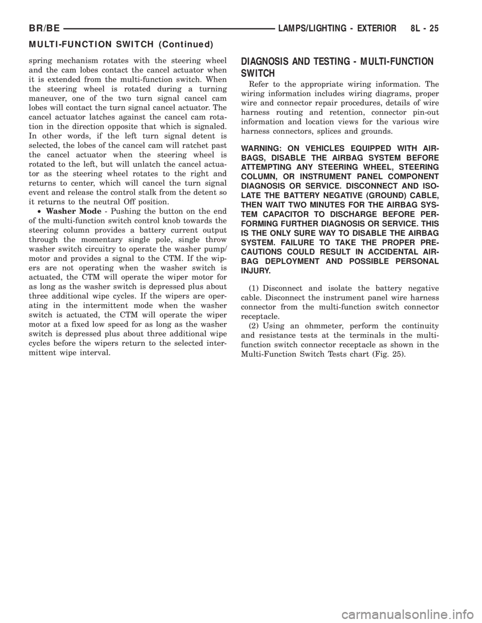
(2) Using an ohmmeter, perform the continuity
and resistance tests at the terminals in the multi-
function switch connector receptacle as shown in the
Multi-Function Switch Tests chart (Fig. 25).
BR/BELAMPS/LIGHTING - EXTERIOR 8L - 25
MULTI-FUNCTION SWITCH (Continued)
Page 624 of 2889
(3) If the multi-function switch fails any of the
continuity or resistance tests, replace the faulty
switch unit as required.
REMOVAL
WARNING: ON VEHICLES EQUIPPED WITH AIR-
BAGS, DISABLE THE AIRBAG SYSTEM BEFORE
ATTEMPTING ANY STEERING WHEEL, STEERING
COLUMN, OR INSTRUMENT PANEL COMPONENT
DIAGNOSIS OR SERVICE. DISCONNECT AND ISO-
LATE THE BATTERY NEGATIVE (GROUND) CABLE,
THEN WAIT TWO MINUTES FOR THE AIRBAG SYS-
TEM CAPACITOR TO DISCHARGE BEFORE PER-
FORMING FURTHER DIAGNOSIS OR SERVICE. THIS
IS THE ONLY SURE WAY TO DISABLE THE AIRBAG
SYSTEM. FAILURE TO TAKE THE PROPER PRE-
CAUTIONS COULD RESULT IN ACCIDENTAL AIR-
BAG DEPLOYMENT AND POSSIBLE PERSONAL
INJURY.
(1) Disconnect and isolate the battery negative
cable.
(2) If the vehicle is so equipped, unscrew the lever
from the tilt steering column adjuster mechanism
located on the left side of the column just below the
multi-function switch control stalk. Turn the lever
counterclockwise to unscrew it from the adjuster.
(3) From below the steering column, remove the
two outboard screws that secure the upper shroud to
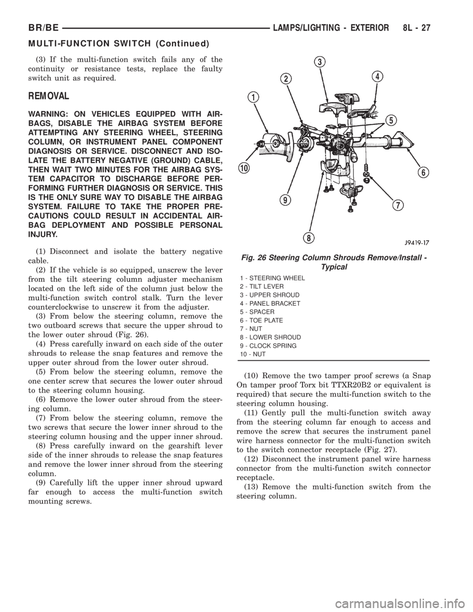
the lower outer shroud (Fig. 26).
(4) Press carefully inward on each side of the outer
shrouds to release the snap features and remove the
upper outer shroud from the lower outer shroud.
(5) From below the steering column, remove the
one center screw that secures the lower outer shroud
to the steering column housing.
(6) Remove the lower outer shroud from the steer-
ing column.
(7) From below the steering column, remove the
two screws that secure the lower inner shroud to the
steering column housing and the upper inner shroud.
(8) Press carefully inward on the gearshift lever
side of the inner shrouds to release the snap features
and remove the lower inner shroud from the steering
column.
(9) Carefully lift the upper inner shroud upward
far enough to access the multi-function switch
mounting screws.(10) Remove the two tamper proof screws (a Snap
On tamper proof Torx bit TTXR20B2 or equivalent is
required) that secure the multi-function switch to the
steering column housing.
(11) Gently pull the multi-function switch away
from the steering column far enough to access and
remove the screw that secures the instrument panel
wire harness connector for the multi-function switch
to the switch connector receptacle (Fig. 27).
(12) Disconnect the instrument panel wire harness
connector from the multi-function switch connector
receptacle.
(13) Remove the multi-function switch from the
steering column.
Fig. 26 Steering Column Shrouds Remove/Install -
Typical
1 - STEERING WHEEL
2 - TILT LEVER
3 - UPPER SHROUD
4 - PANEL BRACKET
5 - SPACER
6 - TOE PLATE
7 - NUT
8 - LOWER SHROUD
9 - CLOCK SPRING
10 - NUT
BR/BELAMPS/LIGHTING - EXTERIOR 8L - 27
MULTI-FUNCTION SWITCH (Continued)
Page 625 of 2889
INSTALLATION
WARNING: ON VEHICLES EQUIPPED WITH AIR-
BAGS, DISABLE THE AIRBAG SYSTEM BEFORE
ATTEMPTING ANY STEERING WHEEL, STEERING
COLUMN, OR INSTRUMENT PANEL COMPONENT
DIAGNOSIS OR SERVICE. DISCONNECT AND ISO-
LATE THE BATTERY NEGATIVE (GROUND) CABLE,
THEN WAIT TWO MINUTES FOR THE AIRBAG SYS-
TEM CAPACITOR TO DISCHARGE BEFORE PER-
FORMING FURTHER DIAGNOSIS OR SERVICE. THIS
IS THE ONLY SURE WAY TO DISABLE THE AIRBAG
SYSTEM. FAILURE TO TAKE THE PROPER PRE-
CAUTIONS COULD RESULT IN ACCIDENTAL AIR-
BAG DEPLOYMENT AND POSSIBLE PERSONAL
INJURY.
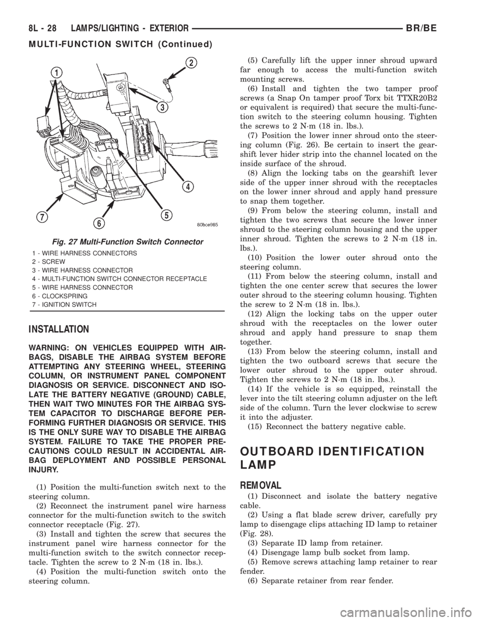
(1) Position the multi-function switch next to the
steering column.
(2) Reconnect the instrument panel wire harness
connector for the multi-function switch to the switch
connector receptacle (Fig. 27).
(3) Install and tighten the screw that secures the
instrument panel wire harness connector for the
multi-function switch to the switch connector recep-
tacle. Tighten the screw to 2 N´m (18 in. lbs.).
(4) Position the multi-function switch onto the
steering column.(5) Carefully lift the upper inner shroud upward
far enough to access the multi-function switch
mounting screws.
(6) Install and tighten the two tamper proof
screws (a Snap On tamper proof Torx bit TTXR20B2
or equivalent is required) that secure the multi-func-
tion switch to the steering column housing. Tighten
the screws to 2 N´m (18 in. lbs.).
(7) Position the lower inner shroud onto the steer-
ing column (Fig. 26). Be certain to insert the gear-
shift lever hider strip into the channel located on the
inside surface of the shroud.
(8) Align the locking tabs on the gearshift lever
side of the upper inner shroud with the receptacles
on the lower inner shroud and apply hand pressure
to snap them together.
(9) From below the steering column, install and
tighten the two screws that secure the lower inner
shroud to the steering column housing and the upper
inner shroud. Tighten the screws to 2 N´m (18 in.
lbs.).
(10) Position the lower outer shroud onto the
steering column.
(11) From below the steering column, install and
tighten the one center screw that secures the lower
outer shroud to the steering column housing. Tighten
the screw to 2 N´m (18 in. lbs.).
(12) Align the locking tabs on the upper outer
shroud with the receptacles on the lower outer
shroud and apply hand pressure to snap them
together.
(13) From below the steering column, install and
tighten the two outboard screws that secure the
lower outer shroud to the upper outer shroud.
Tighten the screws to 2 N´m (18 in. lbs.).
(14) If the vehicle is so equipped, reinstall the
lever into the tilt steering column adjuster on the left
side of the column. Turn the lever clockwise to screw
it into the adjuster.
(15) Reconnect the battery negative cable.
OUTBOARD IDENTIFICATION
LAMP
REMOVAL
(1) Disconnect and isolate the battery negative
cable.
(2) Using a flat blade screw driver, carefully pry
lamp to disengage clips attaching ID lamp to retainer
(Fig. 28).
(3) Separate ID lamp from retainer.
(4) Disengage lamp bulb socket from lamp.
(5) Remove screws attaching lamp retainer to rear
fender.
(6) Separate retainer from rear fender.
Fig. 27 Multi-Function Switch Connector
1 - WIRE HARNESS CONNECTORS
2 - SCREW
3 - WIRE HARNESS CONNECTOR
4 - MULTI-FUNCTION SWITCH CONNECTOR RECEPTACLE
5 - WIRE HARNESS CONNECTOR
6 - CLOCKSPRING
7 - IGNITION SWITCH
8L - 28 LAMPS/LIGHTING - EXTERIORBR/BE
MULTI-FUNCTION SWITCH (Continued)
Page 628 of 2889
ary. The rotor of the clockspring, including the turn
signal cancel cam lobes rotate with the steering
wheel.
The turn signal cancel cam is serviced as a unit
with the clockspring and cannot be repaired. If faulty
or damaged, the entire clockspring unit must be
replaced. (Refer to 8 - ELECTRICAL/RESTRAINTS/
CLOCKSPRING - REMOVAL).
OPERATION
The turn signal cancel cam has two lobes molded
into the lower surface of the clockspring rotor. When
the turn signals are activated by moving the multi-
function switch control stalk to a detent position, a
turn signal cancel actuator is extended from the
inside surface of the multi-function switch housing
toward the center of the steering column and theturn signal cancel cam. When the steering wheel is
rotated during a turning maneuver, one of the two
turn signal cancel cam lobes will contact the turn sig-
nal cancel actuator. The cancel actuator latches
against the cancel cam rotation in the direction oppo-
site that which is signaled. In other words, if the left
turn signal detent is selected, the lobes of the cancel
cam will ratchet past the cancel actuator when the
steering wheel is rotated to the left, but will unlatch
the cancel actuator as the steering wheel rotates to
the right and returns to center, which will cancel the
turn signal event and release the control stalk from
the detent so it returns to the neutral Off position.
UNDERHOOD LAMP
REMOVAL
(1) Disconnect and isolate the battery negative
cable.
(2) Insert a small flat blade in the access slot
between the lamp base and lamp lens.
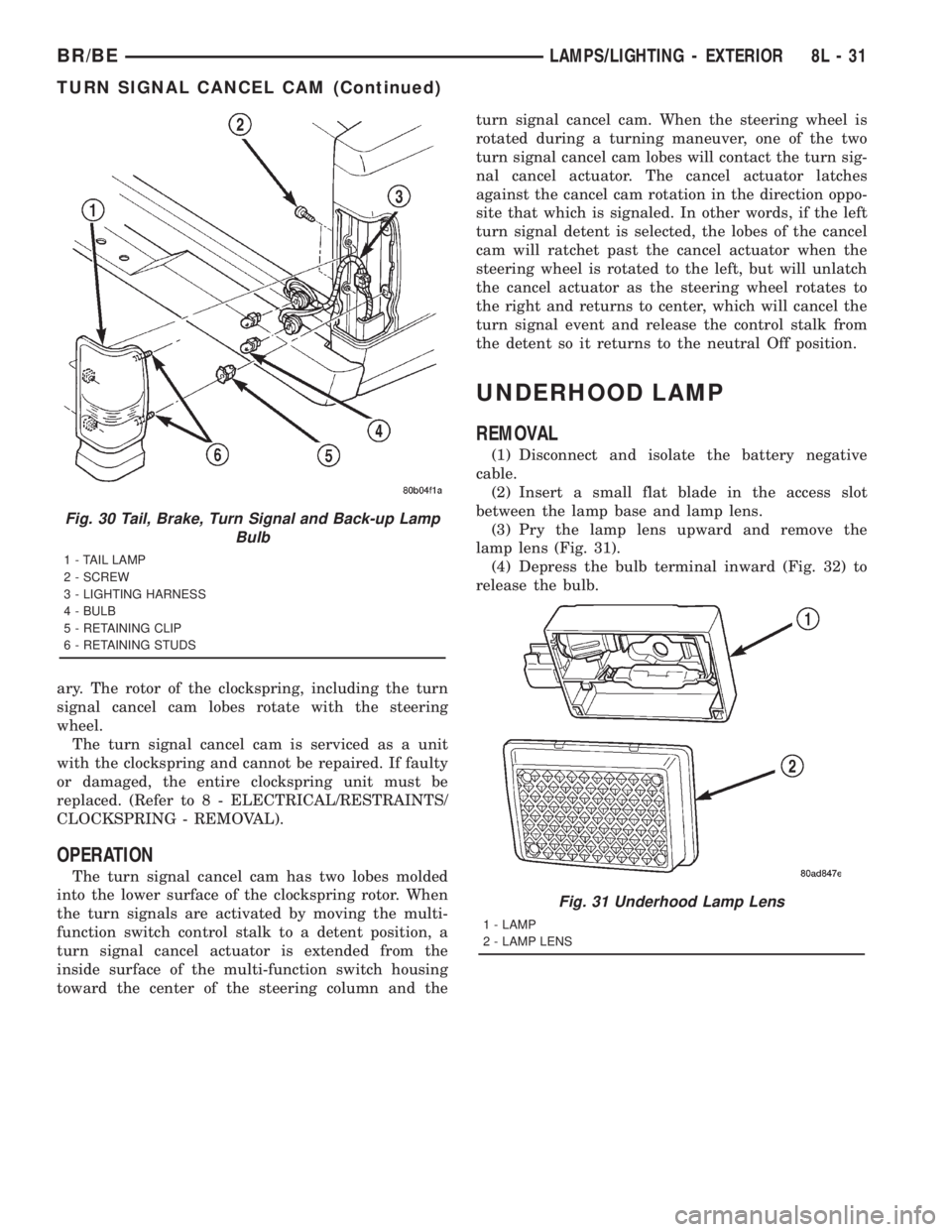
(3) Pry the lamp lens upward and remove the
lamp lens (Fig. 31).
(4) Depress the bulb terminal inward (Fig. 32) to
release the bulb.
Fig. 30 Tail, Brake, Turn Signal and Back-up Lamp
Bulb
1 - TAIL LAMP
2 - SCREW
3 - LIGHTING HARNESS
4 - BULB
5 - RETAINING CLIP
6 - RETAINING STUDS
Fig. 31 Underhood Lamp Lens
1 - LAMP
2 - LAMP LENS
BR/BELAMPS/LIGHTING - EXTERIOR 8L - 31
TURN SIGNAL CANCEL CAM (Continued)
Page 631 of 2889
DOOR AJAR SWITCH
DESCRIPTION
The door ajar switches are mounted to the door
hinge pillars. The switches close a path to ground for
the Central Timer Module (CTM) when a door is
opened, and open the ground path when a door is
closed.
The door ajar switches cannot be repaired and, if
faulty or damaged, they must be replaced.
DIAGNOSIS AND TESTING - DOOR AJAR
SWITCH
For circuit descriptions and diagrams, refer to the
appropriate wiring information. The wiring informa-tion includes wiring diagrams, proper wire and con-
nector repair procedures, details of wire harness
routing and retention, connector pin-out information
and location views for the various wire harness con-
nectors, splices and grounds.
WARNING: ON VEHICLES EQUIPPED WITH AIR-
BAGS, REFER TO ELECTRICAL, RESTRAINTS
BEFORE ATTEMPTING ANY STEERING WHEEL,
STEERING COLUMN, OR INSTRUMENT PANEL
COMPONENT DIAGNOSIS OR SERVICE. FAILURE
TO TAKE THE PROPER PRECAUTIONS COULD
RESULT IN ACCIDENTAL AIRBAG DEPLOYMENT
AND POSSIBLE PERSONAL INJURY.
(1) Rotate the headlamp switch knob counterclock-
wise to ensure that the dome lamps are not switched
off. Open the driver door and note whether the inte-
rior lamps light. They should light. If OK, (Refer to 8
- ELECTRICAL/LAMPS/LIGHTING - EXTERIOR/
HEADLAMP SWITCH - DIAGNOSIS AND TEST-
ING). If not OK, go to Step 2.
(2) Disconnect and isolate the battery negative
cable. Unplug the driver door ajar switch from its
wire harness connector. Check for continuity between
the ground circuit cavity of the driver door ajar
switch wire harness connector and a good ground.
There should be continuity. If OK, go to Step 3. If not
OK, repair the circuit to ground as required.
(3) Check for continuity between the door ajar
switch ground circuit terminal and each of the other
two terminals of the driver door ajar switch. There
should be continuity with the switch plunger
released, and no continuity with the switch plunger
depressed. If OK, go to Step 4. If not OK, replace the
faulty switch.
(4) Remove the Central Timer Module (CTM) from
its mounting bracket to access the CTM wire harness
connectors (Refer to 8 - ELECTRICAL/ELECTRONIC
CONTROL MODULES/BODY CONTROL/CENTRAL
TIMER MODUL - REMOVAL). Unplug the 14-way
CTM wire harness connector. Check for continuity
between the driver door switch sense circuit cavity of
the 14-way CTM wire harness connector and a good
ground. There should be no continuity. If OK, go to
Step 5. If not OK, repair the short circuit as
required.
(5) Check for continuity between the driver door
switch sense circuit cavities of the 14-way CTM wire
harness connector and the driver door ajar switch
wire harness connector. There should be continuity. If
OK, (Refer to 8 - ELECTRICAL/LAMPS/LIGHTING -
EXTERIOR/HEADLAMP SWITCH - DIAGNOSIS
AND TESTING) If not OK, repair the open circuit as
required.
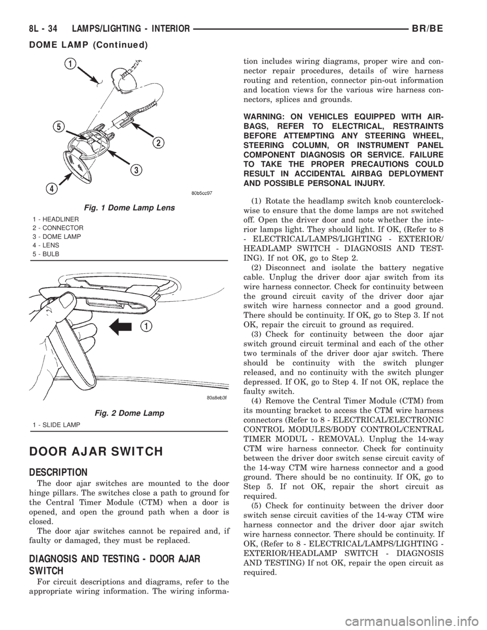
Fig. 1 Dome Lamp Lens
1 - HEADLINER
2 - CONNECTOR
3 - DOME LAMP
4 - LENS
5 - BULB
Fig. 2 Dome Lamp
1 - SLIDE LAMP
8L - 34 LAMPS/LIGHTING - INTERIORBR/BE
DOME LAMP (Continued)
Page 633 of 2889
(5) Install the glove box onto the instrument panel.
(Refer to 23 - BODY/INSTRUMENT PANEL/GLOVE
BOX - INSTALLATION) for the procedures.
(6) Close the glove box.
(7) Reconnect the battery negative cable.
READING LAMP
DESCRIPTION
The overhead console in this vehicle is equipped
with two individual reading and courtesy lamps. The
lamp lenses are the only visible components of these
lamps. The reading and courtesy lamp lenses are
mounted in the overhead console housing between
the garage door opener storage bin and the sun-
glasses storage bin. Each lamp has its own switch,
bulb, reflector and lens; but both lamps share a com-
mon lamp housing within the overhead console.
The overhead console reading and courtesy lamps
operate on battery current that is provided at all
times, regardless of the ignition switch position. The
ground feed for the lamps is switched through the
integral reading and courtesy lamp switches or
through the door jamb switches. Each lamp is
designed and aimed to provide illumination that will
be directed only to that side of the vehicle on which
the lamp is located.
The reading and courtesy lamp lenses, bulbs and
the lamp housing and reflector unit are available for
service replacement. The reading and courtesy lamp
switches, bulb holders and wiring are only available
as part of the overhead console wire harness. If
either of the lamp switches or bulb holders is faulty
or damaged, the entire overhead console wire har-
ness assembly must be replaced.
For service of the reading and courtesy lamp bulbs,
refer to the appropriate wiring information. The wir-
ing information includes wiring diagrams, proper
wire and connector repair procedures, details of wire
harness routing and retention, connector pin-out
information and location views for the various wire
harness connectors, splices and grounds.
OPERATION
All reading and courtesy lamps located in the over-
head console are activated by the door jamb switches.
When all of the doors are closed, these lamps can be
individually activated by depressing the correspond-
ing lens. When any door is open, depressing the lamp
lenses to activate the lamp switches will not turn the
lamps off.
See the owner's manual in the vehicle glove box for
more information on the use and operation of the
overhead console reading and courtesy lamps.
REMOVAL
(1) Disconnect and isolate the battery negative
cable.
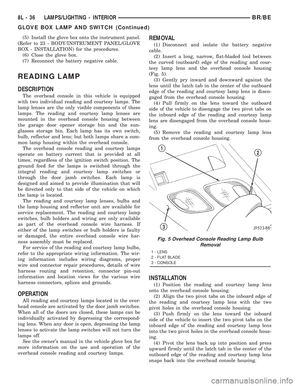
(2) Insert a long, narrow, flat-bladed tool between
the curved (outboard) edge of the reading and cour-
tesy lamp lens and the overhead console housing
(Fig. 5).
(3) Gently pry inward and downward against the
lens until the latch tab in the center of the outboard
edge of the reading and courtesy lamp lens is disen-
gaged from the overhead console housing.
(4) Pull firmly on the lens toward the outboard
side of the vehicle to disengage the two pivot tabs on
the inboard edge of the reading and courtesy lamp
lens are disengaged from the overhead console hous-
ing.
(5) Remove the reading and courtesy lamp lens
from the overhead console housing.
INSTALLATION
(1) Position the reading and courtesy lamp lens
onto the overhead console housing.
(2) Align the two pivot tabs on the inboard edge of
the reading and courtesy lamp lens with the two
pivot holes in the overhead console housing.
(3) Push firmly on the lens toward the inboard
side of the vehicle to insert the two pivot tabs on the
inboard edge of the reading and courtesy lamp lens
into the two pivot holes in the overhead console hous-
ing.
(4) Pivot the lens back up into position and press
upward firmly until the latch tab in the center of the
outboard edge of the reading and courtesy lamp lens
snaps back into the overhead console housing.
Fig. 5 Overhead Console Reading Lamp Bulb
Removal
1 - LENS
2 - FLAT BLADE
3 - CONSOLE
8L - 36 LAMPS/LIGHTING - INTERIORBR/BE
GLOVE BOX LAMP AND SWITCH (Continued)