2001 DODGE RAM service
[x] Cancel search: servicePage 1574 of 2889
FUEL INJECTION - DIESEL
TABLE OF CONTENTS
page page
FUEL INJECTION - DIESEL
DESCRIPTION...........................87
DIAGNOSIS AND TESTING.................89
BOOST PRESSURE.....................89
SPECIFICATIONS........................90
ACCELERATOR PEDAL POSITION SENSOR
DESCRIPTION...........................91
OPERATION.............................91
REMOVAL..............................91
INSTALLATION...........................93
FUEL INJECTOR
DESCRIPTION...........................93
OPERATION.............................94
DIAGNOSIS AND TESTING.................95
FUEL INJECTOR TEST...................95
REMOVAL..............................96
INSTALLATION...........................98
FUEL INJECTION PUMP RELAY
DESCRIPTION...........................99
OPERATION.............................99
FUEL TEMPERATURE SENSOR
DESCRIPTION...........................99
OPERATION............................100
INTAKE AIR HEATER
DESCRIPTION..........................100OPERATION............................100
REMOVAL.............................100
INSTALLATION..........................101
INTAKE AIR HEATER RELAY
DESCRIPTION..........................101
OPERATION............................102
REMOVAL.............................102
INSTALLATION..........................102
INTAKE AIR TEMPERATURE SENSOR
DESCRIPTION..........................102
OPERATION............................102
REMOVAL.............................103
INSTALLATION..........................103
MAP SENSOR
DESCRIPTION..........................103
OPERATION............................103
REMOVAL.............................104
INSTALLATION..........................104
PTO SWITCH
DESCRIPTION..........................104
THROTTLE CONTROL CABLE
REMOVAL.............................104
INSTALLATION..........................105
FUEL INJECTION - DIESEL
DESCRIPTION - DIESEL FUEL INJECTION
SYSTEM
The Engine Control Module (ECM) and Fuel Injec-
tion Pump Control Module (FPCM) are used prima-
rily for fuel system control. The ECM is a separate
replaceable component, while the FPCM is internal
to the fuel injection pump and is a non-serviceable
part. The ECM and FPCM are interconnected (wired
together) for fuel injection control.The Powertrain Control Module (PCM) is used to
regulate or control the A/C, charging and speed con-
trol systems. It is also used to partially control cer-
tain electronic automatic transmission components.
The PCM also has control over certain instrument
panel components.
Refer to either Powertrain Control Module (PCM)
or Engine Control Module (ECM) for additional infor-
mation. Refer to (Fig. 1) for a partial list of fuel sys-
tem components.
BR/BEFUEL INJECTION - DIESEL 14 - 87
Page 1578 of 2889
ACCELERATOR PEDAL
POSITION SENSOR
DESCRIPTION
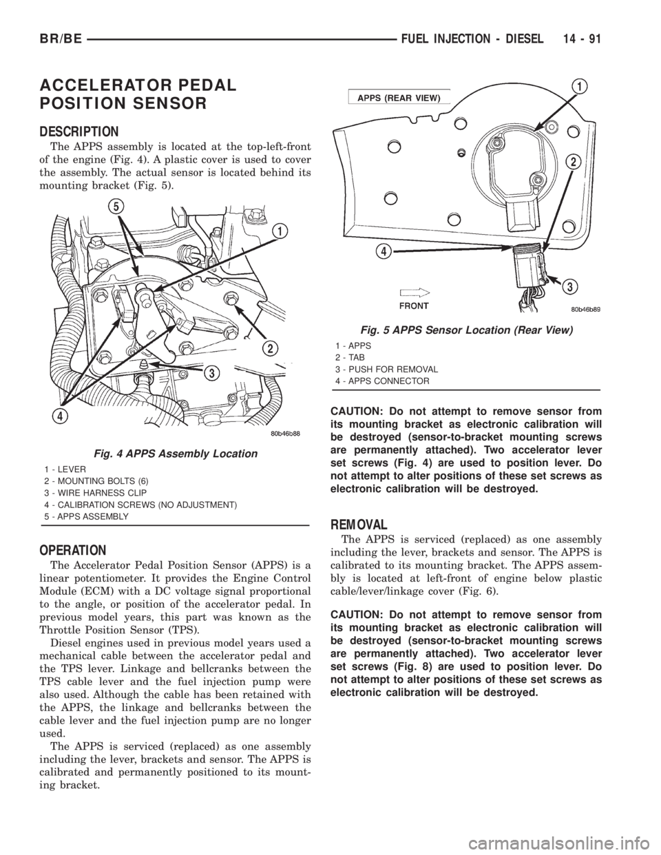
The APPS assembly is located at the top-left-front
of the engine (Fig. 4). A plastic cover is used to cover
the assembly. The actual sensor is located behind its
mounting bracket (Fig. 5).
OPERATION
The Accelerator Pedal Position Sensor (APPS) is a
linear potentiometer. It provides the Engine Control
Module (ECM) with a DC voltage signal proportional
to the angle, or position of the accelerator pedal. In
previous model years, this part was known as the
Throttle Position Sensor (TPS).
Diesel engines used in previous model years used a
mechanical cable between the accelerator pedal and
the TPS lever. Linkage and bellcranks between the
TPS cable lever and the fuel injection pump were
also used. Although the cable has been retained with
the APPS, the linkage and bellcranks between the
cable lever and the fuel injection pump are no longer
used.
The APPS is serviced (replaced) as one assembly
including the lever, brackets and sensor. The APPS is
calibrated and permanently positioned to its mount-
ing bracket.CAUTION: Do not attempt to remove sensor from
its mounting bracket as electronic calibration will
be destroyed (sensor-to-bracket mounting screws
are permanently attached). Two accelerator lever
set screws (Fig. 4) are used to position lever. Do
not attempt to alter positions of these set screws as
electronic calibration will be destroyed.
REMOVAL
The APPS is serviced (replaced) as one assembly
including the lever, brackets and sensor. The APPS is
calibrated to its mounting bracket. The APPS assem-
bly is located at left-front of engine below plastic
cable/lever/linkage cover (Fig. 6).
CAUTION: Do not attempt to remove sensor from
its mounting bracket as electronic calibration will
be destroyed (sensor-to-bracket mounting screws
are permanently attached). Two accelerator lever
set screws (Fig. 8) are used to position lever. Do
not attempt to alter positions of these set screws as
electronic calibration will be destroyed.
Fig. 4 APPS Assembly Location
1 - LEVER
2 - MOUNTING BOLTS (6)
3 - WIRE HARNESS CLIP
4 - CALIBRATION SCREWS (NO ADJUSTMENT)
5 - APPS ASSEMBLY
Fig. 5 APPS Sensor Location (Rear View)
1 - APPS
2-TAB
3 - PUSH FOR REMOVAL
4 - APPS CONNECTOR
BR/BEFUEL INJECTION - DIESEL 14 - 91
Page 1580 of 2889
(1) Disconnect both negative battery cables at both
batteries.
(2) Remove cable cover (Fig. 6). Cable cover is
attached with 2 Phillips screws, 2 plastic retention
clips and 2 push tabs (Fig. 6). Remove 2 Phillips
screws and carefully pry out 2 retention clips. After
clip removal, push rearward on front tab, and
upward on lower tab for cover removal.
(3) Using finger pressure only, disconnect end of
speed control servo cable from throttle lever pin by
pulling forward on connector while holding lever
rearward (Fig. 7).DO NOT try to pull connector
off perpendicular to lever pin. Connector will
be broken.
(4) Using two small screwdrivers, pry throttle
cable connector socket from throttle lever ball (Fig.
7).Be very careful not to bend throttle lever
arm.
(5) Disconnect transmission control cable at lever
arm (if equipped). Refer to 21, Transmission.
(6) Squeeze pinch tabs on speed control cable (Fig.
7) and pull cable rearward to remove from cable
mounting bracket.
(7) Squeeze pinch tabs on throttle cable (Fig. 7)
and pull cable rearward to remove from cable mount-
ing bracket.
(8) If equipped with an automatic transmission,
refer to 21, Transmission for transmission control
cable removal procedures.
(9) Disconnect wiring harness clip (Fig. 8) at bot-
tom of bracket.
(10) Remove 6 mounting bolts (Fig. 8) and par-
tially remove APPS assembly from engine. After
assembly is partially removed, disconnect electrical
connector from bottom of sensor by pushing on con-
nector tab (Fig. 9).
(11) Remove APPS assembly from engine.
INSTALLATION
The APPS is serviced (replaced) as one assembly
including the lever, brackets and sensor. The APPS is
calibrated to its mounting bracket. The APPS assem-
bly is located at left-front of engine below plastic
cable/lever/linkage cover (Fig. 6).
(1) Snap electrical connector into bottom of sensor.
(2) Position APPS assembly to engine and install 6
bolts. Tighten bolts to 12 N´m (105 in. lbs.) torque.
(3) Connect wiring harness clip (Fig. 8) at bottom
of bracket.
(4) If equipped with an automatic transmission,
refer to Group 21, Transmission for transmission con-
trol cable installation procedures.
(5) Install speed control cable into mounting
bracket. Be sure pinch tabs (Fig. 7) have secured
cable.(6) Install throttle cable into mounting bracket. Be
sure pinch tabs (Fig. 7) have secured cable.
(7) Connect throttle cable at lever (snaps on).
(8) Connect speed control cable to lever by pushing
cable connector rearward onto lever pin while hold-
ing lever forward.
(9) Install cable cover.
(10) Connect both negative battery cables to both
batteries.
(11)ECM Calibration:Turn key to ON position.
Without starting engine, slowly press throttle pedal
to floor and then slowly release. This step must be
done (one time) to ensure accelerator pedal position
sensor calibration has been learned by ECM. If not
done, possible DTC's may be set.
(12) Use DRB scan tool to erase any DTC's from
ECM/PCM.
FUEL INJECTOR
DESCRIPTION
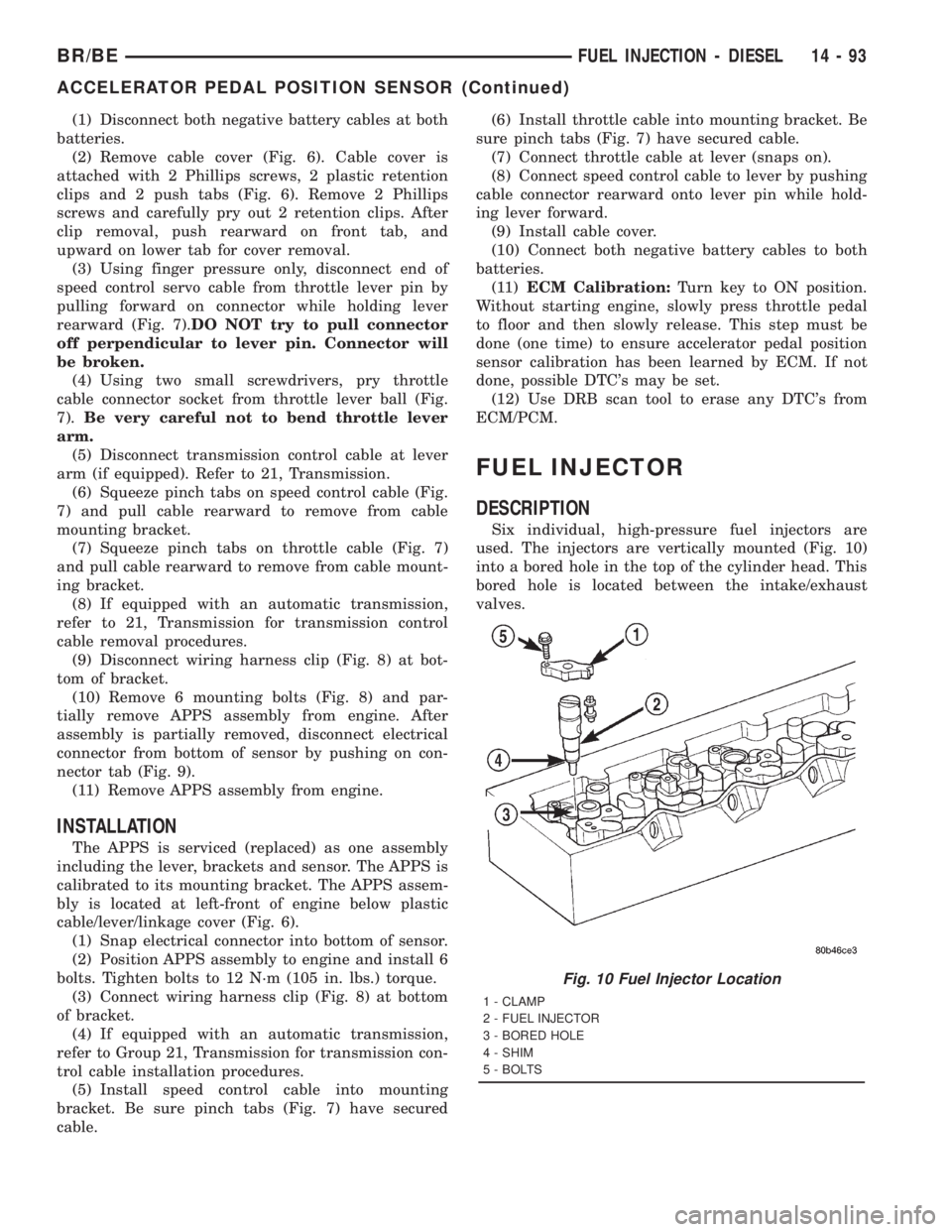
Six individual, high-pressure fuel injectors are
used. The injectors are vertically mounted (Fig. 10)
into a bored hole in the top of the cylinder head. This
bored hole is located between the intake/exhaust
valves.
Fig. 10 Fuel Injector Location
1 - CLAMP
2 - FUEL INJECTOR
3 - BORED HOLE
4 - SHIM
5 - BOLTS
BR/BEFUEL INJECTION - DIESEL 14 - 93
ACCELERATOR PEDAL POSITION SENSOR (Continued)
Page 1586 of 2889
(g) If any of these conditions occur, replace injec-
tor.
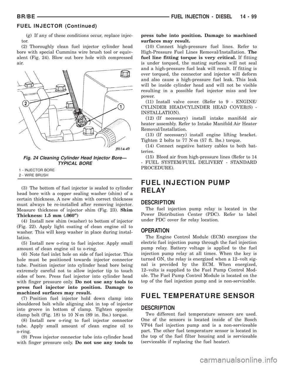
(2) Thoroughly clean fuel injector cylinder head
bore with special Cummins wire brush tool or equiv-
alent (Fig. 24). Blow out bore hole with compressed
air.
(3) The bottom of fuel injector is sealed to cylinder
head bore with a copper sealing washer (shim) of a
certain thickness. A new shim with correct thickness
must always be re-installed after removing injector.
Measure thickness of injector shim (Fig. 23).Shim
Thickness: 1.5 mm (.060º)
(4) Install new shim (washer) to bottom of injector
(Fig. 22). Apply light coating of clean engine oil to
washer. This will keep washer in place during instal-
lation.
(5) Install new o-ring to fuel injector. Apply small
amount of clean engine oil to o-ring.
(6) Note fuel inlet hole on side of fuel injector. This
hole must be positioned towards injector connector
tube. Position injector into cylinder head bore being
extremely careful not to allow injector tip to touch
sides of bore. Press fuel injector into cylinder head
with finger pressure only.Do not use any tools to
press fuel injector into position. Damage to
machined surfaces may result.
(7) Position fuel injector hold down clamp into
shouldered bolt while aligning slot in top of injector
into groove in bottom of clamp. Tighten opposite
clamp bolt (Fig. 18) to 10 N´m (89 in. lbs.) torque.
(8) Install new o-ring to fuel injector connector
tube. Apply small amount of clean engine oil to
o-ring.
(9) Press injector connector tube into cylinder head
with finger pressure only.Do not use any tools topress tube into position. Damage to machined
surfaces may result.
(10) Connect high-pressure fuel lines. Refer to
High-Pressure Fuel Lines Removal/Installation.The
fuel line fitting torque is very critical.If fitting
is under torqued, the mating surfaces will not seal
and a high-pressure fuel leak will result. If fitting is
over torqued, the connector and injector will deform
and also cause a high-pressure fuel leak. This leak
will be inside cylinder head and will not be visible
resulting in a possible fuel injector miss and low
power.
(11) Install valve cover. (Refer to 9 - ENGINE/
CYLINDER HEAD/CYLINDER HEAD COVER(S) -
INSTALLATION).
(12) (If necessary) install intake manifold air
heater assembly. Refer to Intake Manifold Air Heater
Removal/Installation.
(13) (If necessary) install engine lifting bracket.
Tighten 2 bolts to 77 N´m (57 ft. lbs.) torque.
(14) Connect negative battery cables to both bat-
teries.
(15) Bleed air from high-pressure lines (Refer to 14
- FUEL SYSTEM/FUEL DELIVERY - STANDARD
PROCEDURE).
FUEL INJECTION PUMP
RELAY
DESCRIPTION
The fuel injection pump relay is located in the
Power Distribution Center (PDC). Refer to label
under PDC cover for relay location.
OPERATION
The Engine Control Module (ECM) energizes the
electric fuel injection pump through the fuel injection
pump relay. Battery voltage is applied to the fuel
injection pump relay at all times. When the key is
turned ON, the relay is energized when a 12±volt sig-
nal is provided by the ECM. When energized,
12±volts is supplied to the Fuel Pump Control Mod-
ule. The Fuel Pump Control Module is located on the
top of the fuel injection pump and is non-servicable.
FUEL TEMPERATURE SENSOR
DESCRIPTION
Two different fuel temperature sensors are used.
One of the sensors is located inside of the Bosch
VP44 fuel injection pump and is a non-serviceable
part. The other fuel temperature sensor is located in
the top of the fuel filter housing and is serviceable
(serviceable if replacing the fuel heater).
Fig. 24 Cleaning Cylinder Head Injector BoreÐ
TYPICAL BORE
1 - INJECTOR BORE
2 - WIRE BRUSH
BR/BEFUEL INJECTION - DIESEL 14 - 99
FUEL INJECTOR (Continued)
Page 1599 of 2889
COLUMN
TABLE OF CONTENTS
page page
COLUMN
DESCRIPTION............................6
OPERATION.............................6
REMOVAL...............................7
INSTALLATION............................8
SPECIFICATIONS.........................9
KEY-IN IGNITION SWITCH
DESCRIPTION............................9
DIAGNOSIS AND TESTING.................10
IGNITION SWITCH AND KEY LOCK
CYLINDER............................10
LOCK CYLINDER HOUSING
REMOVAL..............................10
INSTALLATION...........................11IGNITION SWITCH
DESCRIPTION...........................11
OPERATION.............................11
DIAGNOSIS AND TESTING.................11
IGNITION SWITCH......................11
REMOVAL..............................12
INSTALLATION...........................12
GEAR SHIFT LEVER
REMOVAL..............................13
INSTALLATION...........................13
STEERING WHEEL
REMOVAL..............................13
INSTALLATION...........................13
COLUMN
DESCRIPTION
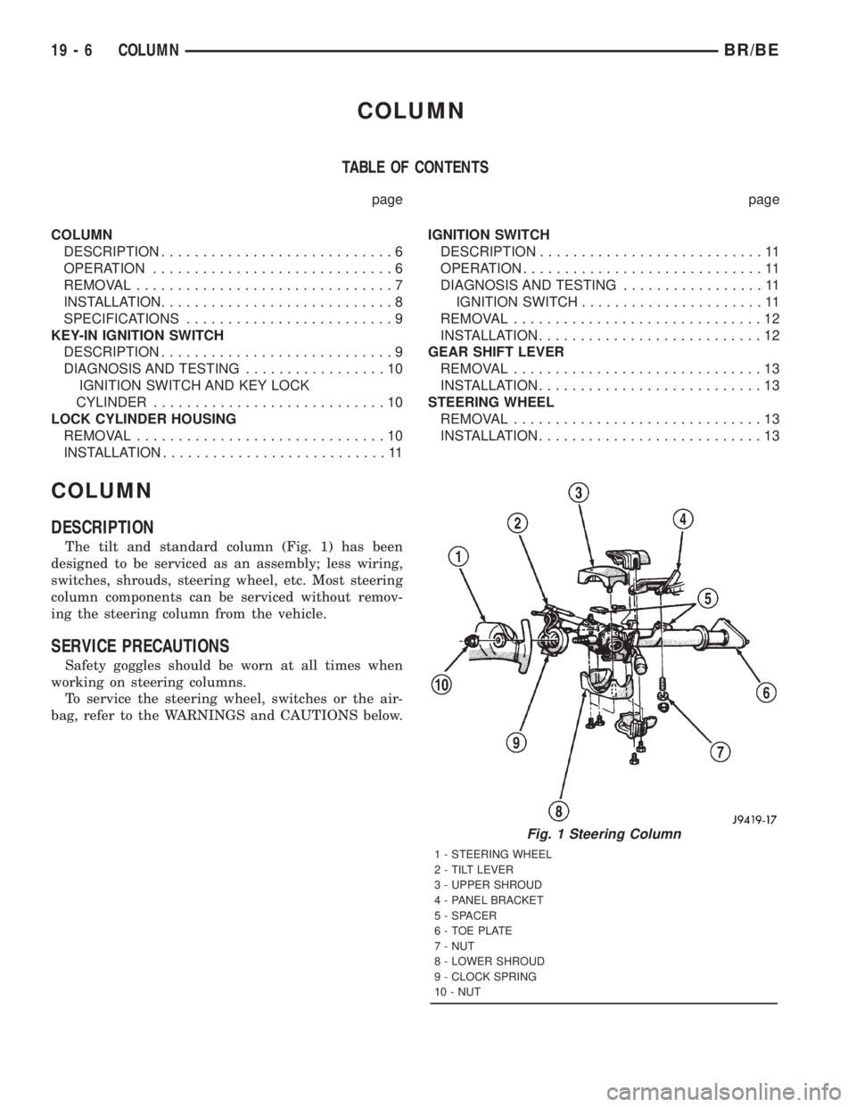
The tilt and standard column (Fig. 1) has been
designed to be serviced as an assembly; less wiring,
switches, shrouds, steering wheel, etc. Most steering
column components can be serviced without remov-
ing the steering column from the vehicle.
SERVICE PRECAUTIONS
Safety goggles should be worn at all times when
working on steering columns.
To service the steering wheel, switches or the air-
bag, refer to the WARNINGS and CAUTIONS below.
Fig. 1 Steering Column
1 - STEERING WHEEL
2 - TILT LEVER
3 - UPPER SHROUD
4 - PANEL BRACKET
5 - SPACER
6 - TOE PLATE
7 - NUT
8 - LOWER SHROUD
9 - CLOCK SPRING
10 - NUT
19 - 6 COLUMNBR/BE
Page 1600 of 2889
WARNING: THE AIRBAG SYSTEM IS A SENSITIVE,
COMPLEX ELECTRO-MECHANICAL UNIT. BEFORE
ATTEMPTING TO DIAGNOSE, REMOVE OR INSTALL
THE AIRBAG SYSTEM COMPONENTS YOU MUST
FIRST DISCONNECT AND ISOLATE THE BATTERY
NEGATIVE (GROUND) CABLE. THEN WAIT TWO
MINUTES FOR THE SYSTEM CAPACITOR TO DIS-
CHARGE. FAILURE TO DO SO COULD RESULT IN
ACCIDENTAL DEPLOYMENT OF THE AIRBAG AND
POSSIBLE PERSONAL INJURY. THE FASTENERS,
SCREWS, AND BOLTS, ORIGINALLY USED FOR
THE AIRBAG COMPONENTS, HAVE SPECIAL COAT-
INGS AND ARE SPECIFICALLY DESIGNED FOR THE
AIRBAG SYSTEM. THEY MUST NEVER BE
REPLACED WITH ANY SUBSTITUTES. ANYTIME A
NEW FASTENER IS NEEDED, REPLACE WITH THE
CORRECT FASTENERS PROVIDED IN THE SERVICE
PACKAGE OR FASTENERS LISTED IN THE PARTS
BOOKS.
CAUTION: Do not hammer on steering column shaft
or shift tube. This may cause the shaft/shift tube to
collapse or damage the bearing.
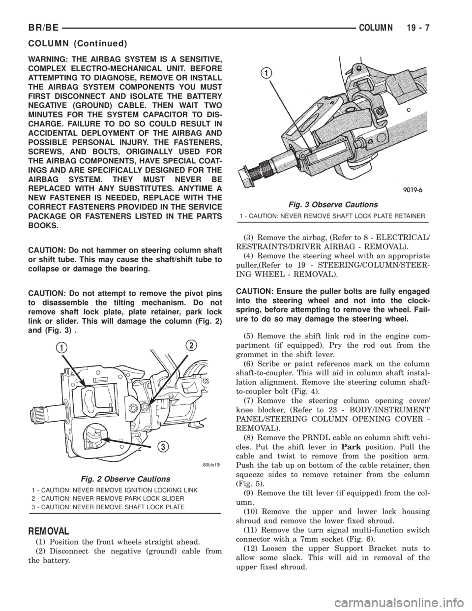
CAUTION: Do not attempt to remove the pivot pins
to disassemble the tilting mechanism. Do not
remove shaft lock plate, plate retainer, park lock
link or slider. This will damage the column (Fig. 2)
and (Fig. 3) .
REMOVAL
(1) Position the front wheels straight ahead.
(2) Disconnect the negative (ground) cable from
the battery.(3) Remove the airbag, (Refer to 8 - ELECTRICAL/
RESTRAINTS/DRIVER AIRBAG - REMOVAL).
(4) Remove the steering wheel with an appropriate
puller,(Refer to 19 - STEERING/COLUMN/STEER-
ING WHEEL - REMOVAL).
CAUTION: Ensure the puller bolts are fully engaged
into the steering wheel and not into the clock-
spring, before attempting to remove the wheel. Fail-
ure to do so may damage the steering wheel.
(5) Remove the shift link rod in the engine com-
partment (if equipped). Pry the rod out from the
grommet in the shift lever.
(6) Scribe or paint reference mark on the column
shaft-to-coupler. This will aid in column shaft instal-
lation alignment. Remove the steering column shaft-
to-coupler bolt (Fig. 4).
(7) Remove the steering column opening cover/
knee blocker, (Refer to 23 - BODY/INSTRUMENT
PANEL/STEERING COLUMN OPENING COVER -
REMOVAL).
(8) Remove the PRNDL cable on column shift vehi-
cles. Put the shift lever inParkposition. Pull the
cable and twist to remove from the position arm.
Push the tab up on bottom of the cable retainer, then
squeeze sides to remove retainer from the column
(Fig. 5).
(9) Remove the tilt lever (if equipped) from the col-
umn.
(10) Remove the upper and lower lock housing
shroud and remove the lower fixed shroud.
(11) Remove the turn signal multi-function switch
connector with a 7mm socket (Fig. 6).
(12) Loosen the upper Support Bracket nuts to
allow some slack. This will aid in removal of the
upper fixed shroud.
Fig. 2 Observe Cautions
1 - CAUTION: NEVER REMOVE IGNITION LOCKING LINK
2 - CAUTION: NEVER REMOVE PARK LOCK SLIDER
3 - CAUTION: NEVER REMOVE SHAFT LOCK PLATE
Fig. 3 Observe Cautions
1 - CAUTION: NEVER REMOVE SHAFT LOCK PLATE RETAINER
BR/BECOLUMN 19 - 7
COLUMN (Continued)
Page 1603 of 2889
DIAGNOSIS AND TESTING - IGNITION SWITCH
AND KEY LOCK CYLINDER
ELECTRICAL DIAGNOSIS
For ignition switch electrical schematics, refer to
Ignition Switch in the appropriate section of Electri-
cal Wiring Diagrams.
MECHANICAL DIAGNOSIS (KEY DIFFICULT TO
ROTATE)
Vehicles equipped with an automatic trans-
mission and a floor mounted shifter:a cable is
used to connect the interlock device in the steering
column assembly, to the transmission floor shift
lever. This interlock device is used to lock the trans-
mission shifter in the PARK position when the key
lock cylinder is rotated to the LOCKED or ACCES-
SORY position. The interlock device within the steer-
ing column is not serviceable. If repair is necessary,
the steering column assembly must be replaced.
(Refer to 19 - STEERING/COLUMN - REMOVAL).
If the ignition key is difficult to rotate to or from
the LOCK or ACCESSORY position, it may not be
the fault of the key cylinder or the steering column
components. The brake transmission shift interlock
cable may be out of adjustment. Refer to Brake
Transmission Shift Interlock Cable Adjustment in
Transmissions for adjustment procedures.
Vehicles equipped with an automatic trans-
mission and a steering column mounted shifter:
an interlock device is located within the steering col-
umn. This interlock device is used to lock the trans-
mission shifter in the PARK position when the key
lock cylinder is in the LOCKED or ACCESSORY
position. If it is difficult to rotate the key to or from
the LOCK or ACCESSORY position, the interlock
device within the steering column may be defective.
This device is not serviceable. If repair is necessary,
the steering column assembly must be replaced.
(Refer to 19 - STEERING/COLUMN - REMOVAL).
Vehicles equipped with a manual transmis-
sion and a floor mounted shifter:on certain mod-
els, a lever is located on the steering column behind
the ignition key lock cylinder. The lever must be
manually operated to allow rotation of the ignition
key lock cylinder to the LOCK or ACCESSORY posi-
tion. If it is difficult to rotate the key to the LOCK or
ACCESSORY position, the lever mechanism may be
defective. This mechanism is not serviceable. If
repair is necessary, the steering column assembly
must be replaced. (Refer to 19 - STEERING/COL-
UMN - REMOVAL).
On other models, the ignition key cylinder must be
depressed to allow it to be rotated into the LOCK or
ACCESSORY position. If it is difficult to rotate the
key to the LOCK or ACCESSORY position, the lockmechanism within the steering column may be defec-
tive. This mechanism is not serviceable. If repair is
necessary, the steering column assembly must be
replaced. (Refer to 19 - STEERING/COLUMN -
REMOVAL).
LOCK CYLINDER HOUSING
REMOVAL
The ignition key must be in the key cylinder for
cylinder removal.
(1) Disconnect negative cable from battery.
(2) If equipped with tilt column, remove tilt lever
by turning it counterclockwise.
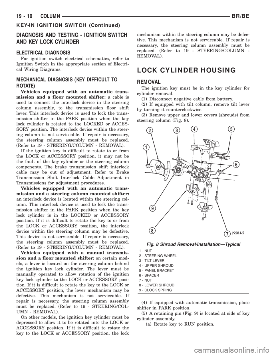
(3) Remove upper and lower covers (shrouds) from
steering column (Fig. 8).
(4) If equipped with automatic transmission, place
shifter in PARK position.
(5) A retaining pin (Fig. 9) is located at side of key
cylinder assembly.
(a) Rotate key to RUN position.
Fig. 8 Shroud Removal/InstallationÐTypical
1 - NUT
2 - STEERING WHEEL
3 - TILT LEVER
4 - UPPER SHROUD
5 - PANEL BRACKET
6 - SPACER
7 - NUT
8 - LOWER SHROUD
9 - CLOCK SPRING
19 - 10 COLUMNBR/BE
KEY-IN IGNITION SWITCH (Continued)
Page 1604 of 2889
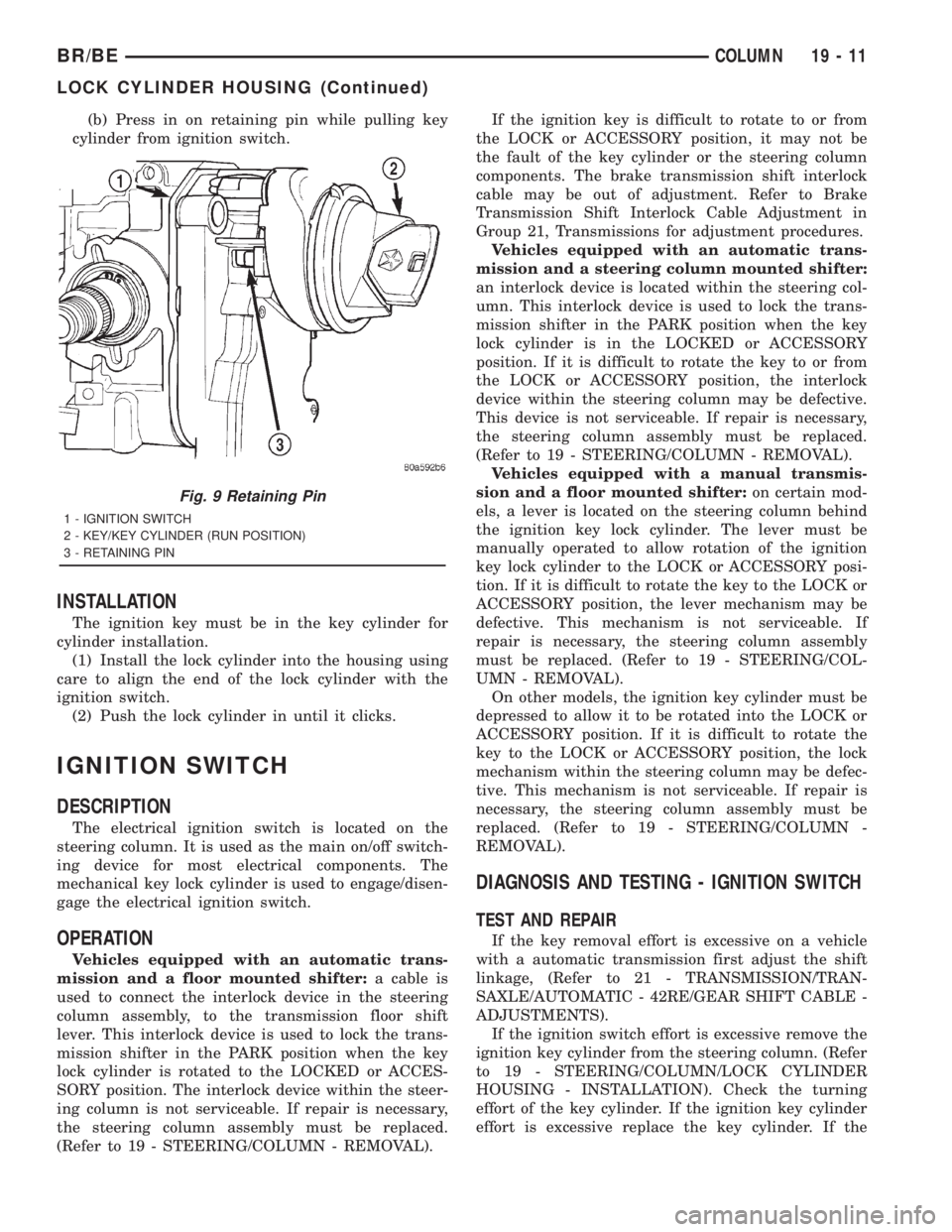
(b) Press in on retaining pin while pulling key
cylinder from ignition switch.
INSTALLATION
The ignition key must be in the key cylinder for
cylinder installation.
(1) Install the lock cylinder into the housing using
care to align the end of the lock cylinder with the
ignition switch.
(2) Push the lock cylinder in until it clicks.
IGNITION SWITCH
DESCRIPTION
The electrical ignition switch is located on the
steering column. It is used as the main on/off switch-
ing device for most electrical components. The
mechanical key lock cylinder is used to engage/disen-
gage the electrical ignition switch.
OPERATION
Vehicles equipped with an automatic trans-
mission and a floor mounted shifter:a cable is
used to connect the interlock device in the steering
column assembly, to the transmission floor shift
lever. This interlock device is used to lock the trans-
mission shifter in the PARK position when the key
lock cylinder is rotated to the LOCKED or ACCES-
SORY position. The interlock device within the steer-
ing column is not serviceable. If repair is necessary,
the steering column assembly must be replaced.
(Refer to 19 - STEERING/COLUMN - REMOVAL).If the ignition key is difficult to rotate to or from
the LOCK or ACCESSORY position, it may not be
the fault of the key cylinder or the steering column
components. The brake transmission shift interlock
cable may be out of adjustment. Refer to Brake
Transmission Shift Interlock Cable Adjustment in
Group 21, Transmissions for adjustment procedures.
Vehicles equipped with an automatic trans-
mission and a steering column mounted shifter:
an interlock device is located within the steering col-
umn. This interlock device is used to lock the trans-
mission shifter in the PARK position when the key
lock cylinder is in the LOCKED or ACCESSORY
position. If it is difficult to rotate the key to or from
the LOCK or ACCESSORY position, the interlock
device within the steering column may be defective.
This device is not serviceable. If repair is necessary,
the steering column assembly must be replaced.
(Refer to 19 - STEERING/COLUMN - REMOVAL).
Vehicles equipped with a manual transmis-
sion and a floor mounted shifter:on certain mod-
els, a lever is located on the steering column behind
the ignition key lock cylinder. The lever must be
manually operated to allow rotation of the ignition
key lock cylinder to the LOCK or ACCESSORY posi-
tion. If it is difficult to rotate the key to the LOCK or
ACCESSORY position, the lever mechanism may be
defective. This mechanism is not serviceable. If
repair is necessary, the steering column assembly
must be replaced. (Refer to 19 - STEERING/COL-
UMN - REMOVAL).
On other models, the ignition key cylinder must be
depressed to allow it to be rotated into the LOCK or
ACCESSORY position. If it is difficult to rotate the
key to the LOCK or ACCESSORY position, the lock
mechanism within the steering column may be defec-
tive. This mechanism is not serviceable. If repair is
necessary, the steering column assembly must be
replaced. (Refer to 19 - STEERING/COLUMN -
REMOVAL).
DIAGNOSIS AND TESTING - IGNITION SWITCH
TEST AND REPAIR
If the key removal effort is excessive on a vehicle
with a automatic transmission first adjust the shift
linkage, (Refer to 21 - TRANSMISSION/TRAN-
SAXLE/AUTOMATIC - 42RE/GEAR SHIFT CABLE -
ADJUSTMENTS).
If the ignition switch effort is excessive remove the
ignition key cylinder from the steering column. (Refer
to 19 - STEERING/COLUMN/LOCK CYLINDER
HOUSING - INSTALLATION). Check the turning
effort of the key cylinder. If the ignition key cylinder
effort is excessive replace the key cylinder. If the
Fig. 9 Retaining Pin
1 - IGNITION SWITCH
2 - KEY/KEY CYLINDER (RUN POSITION)
3 - RETAINING PIN
BR/BECOLUMN 19 - 11
LOCK CYLINDER HOUSING (Continued)