2001 DODGE RAM service
[x] Cancel search: servicePage 1836 of 2889
STANDARD PROCEDURE - FLUID AND FILTER
REPLACEMENT
For proper service intervals (Refer to LUBRICA-
TION & MAINTENANCE/MAINTENANCE SCHED-
ULES - DESCRIPTION). The service fluid fill after a
filter change is approximately 3.8 liters (4.0 quarts).
(1) Hoist and support vehicle on safety stands.
(2) Place a large diameter shallow drain pan
beneath the transmission pan.
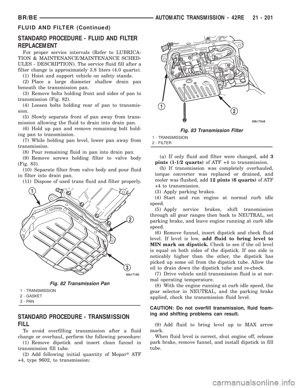
(3) Remove bolts holding front and sides of pan to
transmission (Fig. 82).
(4) Loosen bolts holding rear of pan to transmis-
sion.
(5) Slowly separate front of pan away from trans-
mission allowing the fluid to drain into drain pan.
(6) Hold up pan and remove remaining bolt hold-
ing pan to transmission.
(7) While holding pan level, lower pan away from
transmission.
(8) Pour remaining fluid in pan into drain pan.
(9) Remove screws holding filter to valve body
(Fig. 83).
(10) Separate filter from valve body and pour fluid
in filter into drain pan.
(11) Dispose of used trans fluid and filter properly.
STANDARD PROCEDURE - TRANSMISSION
FILL
To avoid overfilling transmission after a fluid
change or overhaul, perform the following procedure:
(1) Remove dipstick and insert clean funnel in
transmission fill tube.
(2) Add following initial quantity of MopartAT F
+4, type 9602, to transmission:(a) If only fluid and filter were changed, add3
pints (1-1/2 quarts)of ATF +4 to transmission.
(b) If transmission was completely overhauled,
torque converter was replaced or drained, and
cooler was flushed, add12 pints (6 quarts)of ATF
+4 to transmission.
(3) Apply parking brakes.
(4) Start and run engine at normal curb idle
speed.
(5) Apply service brakes, shift transmission
through all gear ranges then back to NEUTRAL, set
parking brake, and leave engine running at curb idle
speed.
(6) Remove funnel, insert dipstick and check fluid
level. If level is low,add fluid to bring level to
MIN mark on dipstick.Check to see if the oil level
is equal on both sides of the dipstick. If one side is
noticably higher than the other, the dipstick has
picked up some oil from the dipstick tube. Allow the
oil to drain down the dipstick tube and re-check.
(7) Drive vehicle until transmission fluid is at nor-
mal operating temperature.
(8) With the engine running at curb idle speed, the
gear selector in NEUTRAL, and the parking brake
applied, check the transmission fluid level.
CAUTION: Do not overfill transmission, fluid foam-
ing and shifting problems can result.
(9) Add fluid to bring level up to MAX arrow
mark.
When fluid level is correct, shut engine off, release
park brake, remove funnel, and install dipstick in fill
tube.
Fig. 82 Transmission Pan
1 - TRANSMISSION
2 - GASKET
3-PAN
Fig. 83 Transmission Filter
1 - TRANSMISSION
2 - FILTER
BR/BEAUTOMATIC TRANSMISSION - 42RE 21 - 201
FLUID AND FILTER (Continued)
Page 1840 of 2889
INSPECTION
Inspect the front clutch components. Replace the
clutch discs if warped, worn, scored, burned or
charred, or if the facing is flaking off. Replace the
steel plates if heavily scored, warped, or broken. Be
sure the driving lugs on the plates are in good con-
dition. The lugs must not be bent, cracked or dam-
aged in any way.
Replace the clutch spring and spring retainer if
either is distorted, warped or broken.
Check the lug grooves in the clutch retainer. The
steel plates should slide freely in the slots. Replace
the retainer if the grooves are worn or damaged.
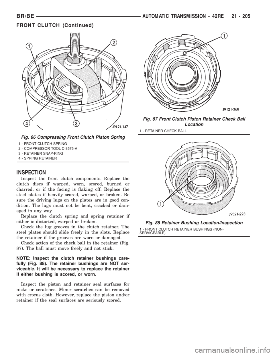
Check action of the check ball in the retainer (Fig.
87). The ball must move freely and not stick.
NOTE: Inspect the clutch retainer bushings care-
fully (Fig. 88). The retainer bushings are NOT ser-
viceable. It will be necessary to replace the retainer
if either bushing is scored, or worn.
Inspect the piston and retainer seal surfaces for
nicks or scratches. Minor scratches can be removed
with crocus cloth. However, replace the piston and/or
retainer if the seal surfaces are seriously scored.
Fig. 86 Compressing Front Clutch Piston Spring
1 - FRONT CLUTCH SPRING
2 - COMPRESSOR TOOL C-3575-A
3 - RETAINER SNAP-RING
4 - SPRING RETAINER
Fig. 87 Front Clutch Piston Retainer Check Ball
Location
1 - RETAINER CHECK BALL
Fig. 88 Retainer Bushing Location/Inspection
1 - FRONT CLUTCH RETAINER BUSHINGS (NON-
SERVICEABLE)
BR/BEAUTOMATIC TRANSMISSION - 42RE 21 - 205
FRONT CLUTCH (Continued)
Page 1851 of 2889
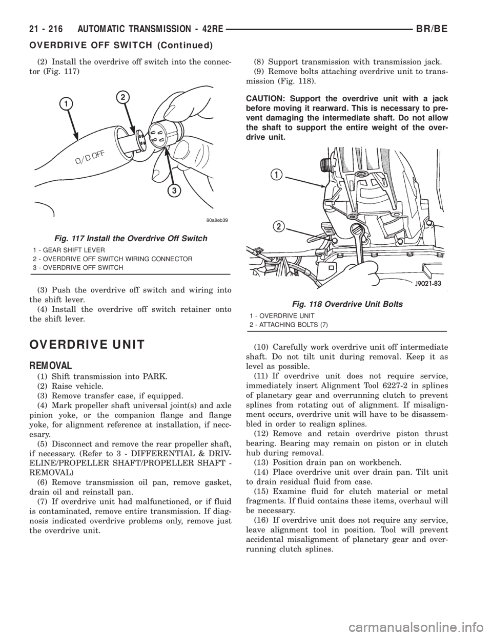
(2) Install the overdrive off switch into the connec-
tor (Fig. 117)
(3) Push the overdrive off switch and wiring into
the shift lever.
(4) Install the overdrive off switch retainer onto
the shift lever.
OVERDRIVE UNIT
REMOVAL
(1) Shift transmission into PARK.
(2) Raise vehicle.
(3) Remove transfer case, if equipped.
(4) Mark propeller shaft universal joint(s) and axle
pinion yoke, or the companion flange and flange
yoke, for alignment reference at installation, if necc-
esary.
(5) Disconnect and remove the rear propeller shaft,
if necessary. (Refer to 3 - DIFFERENTIAL & DRIV-
ELINE/PROPELLER SHAFT/PROPELLER SHAFT -
REMOVAL)
(6) Remove transmission oil pan, remove gasket,
drain oil and reinstall pan.
(7) If overdrive unit had malfunctioned, or if fluid
is contaminated, remove entire transmission. If diag-
nosis indicated overdrive problems only, remove just
the overdrive unit.(8) Support transmission with transmission jack.
(9) Remove bolts attaching overdrive unit to trans-
mission (Fig. 118).
CAUTION: Support the overdrive unit with a jack
before moving it rearward. This is necessary to pre-
vent damaging the intermediate shaft. Do not allow
the shaft to support the entire weight of the over-
drive unit.
(10) Carefully work overdrive unit off intermediate
shaft. Do not tilt unit during removal. Keep it as
level as possible.
(11) If overdrive unit does not require service,
immediately insert Alignment Tool 6227-2 in splines
of planetary gear and overrunning clutch to prevent
splines from rotating out of alignment. If misalign-
ment occurs, overdrive unit will have to be disassem-
bled in order to realign splines.
(12) Remove and retain overdrive piston thrust
bearing. Bearing may remain on piston or in clutch
hub during removal.
(13) Position drain pan on workbench.
(14) Place overdrive unit over drain pan. Tilt unit
to drain residual fluid from case.
(15) Examine fluid for clutch material or metal
fragments. If fluid contains these items, overhaul will
be necessary.
(16) If overdrive unit does not require any service,
leave alignment tool in position. Tool will prevent
accidental misalignment of planetary gear and over-
running clutch splines.
Fig. 117 Install the Overdrive Off Switch
1 - GEAR SHIFT LEVER
2 - OVERDRIVE OFF SWITCH WIRING CONNECTOR
3 - OVERDRIVE OFF SWITCH
Fig. 118 Overdrive Unit Bolts
1 - OVERDRIVE UNIT
2 - ATTACHING BOLTS (7)
21 - 216 AUTOMATIC TRANSMISSION - 42REBR/BE
OVERDRIVE OFF SWITCH (Continued)
Page 1859 of 2889
GEAR CASE AND PARK LOCK
(1) Remove locating ring from gear case.
(2) Remove park pawl shaft retaining bolt and
remove shaft, pawl and spring.
(3) Remove reaction plug snap-ring and remove
reaction plug.
(4) Remove output shaft seal.
CLEANING
Clean the geartrain and case components with sol-
vent. Dry all parts except the bearings with com-
pressed air. Allow bearings to air dry.
Do not use shop towels for wiping parts dry unless
the towels are made from a lint-free material. A suf-
ficient quantity of lint (from shop towels, cloths, rags,
etc.) could plug the transmission filter and fluid pas-
sages.
Discard the old case gasket and seals. Do not
attempt to salvage these parts. They are not reus-
able. Replace any of the overdrive unit snap-rings if
distorted or damaged.
Minor nicks or scratches on components can be
smoothed with crocus cloth. However, do not attempt
to reduce severe scoring on any components with
abrasive materials. Replace severely scored compo-
nents; do not try to salvage them.
INSPECTION
Check condition of the park lock components and
the overdrive case.
Check the bushings in the overdrive case. Replace
the bushings if severely scored or worn. Also replace
the case seal if loose, distorted, or damaged.
Examine the overdrive and direct clutch discs and
plates. Replace the discs if the facing is worn,
severely scored, or burned and flaking off. Replace
the clutch plates if worn, heavily scored, or cracked.
Check the lugs on the clutch plates for wear. The
plates should slide freely in the drum. Replace the
plates or drum if binding occurs.
Check condition of the annulus gear, direct clutch
hub, clutch drum and clutch spring. Replace the gear,
hub and drum if worn or damaged. Replace the
spring if collapsed, distorted, or cracked.
Be sure the splines and lugs on the gear, drum and
hub are in good condition. The clutch plates and
discs should slide freely in these components.
Inspect the thrust bearings and spring plate.
Replace the plate if worn or scored. Replace the bear-
ings if rough, noisy, brinnelled, or worn.
Inspect the planetary gear assembly and the sun
gear and bushings. If either the sun gear or the
bushings are damaged, replace the gear and bush-
ings as an assembly. The gear and bushings are not
serviced separately.
The planetary carrier and pinions must be in good
condition. Also be sure the pinion pins are secure and
in good condition. Replace the carrier if worn or dam-
aged.
Inspect the overrunning clutch and race. The race
surface should be smooth and free of scores. Replace
the overrunning clutch assembly or the race if either
assembly is worn or damaged in any way.
Replace the shaft pilot bushing and inner bushing
if damaged. Replace either shaft bearing if rough or
noisy. Replace the bearing snap-rings if distorted or
cracked.
Check the machined surfaces on the output shaft.
These surfaces should clean and smooth. Very minor
nicks or scratches can be smoothed with crocus cloth.
Replace the shaft if worn, scored or damaged in any
way.
Inspect the output shaft bushings. The small bush-
ing is the intermediate shaft pilot bushing. The large
bushing is the overrunning clutch hub bushing.
Replace either bushing if scored, pitted, cracked, or
worn.
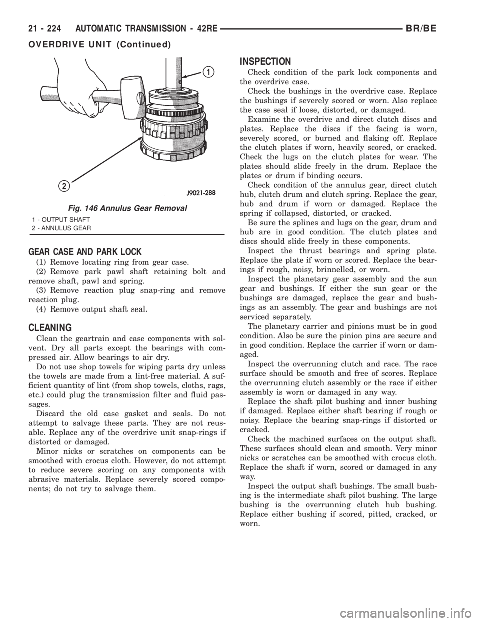
Fig. 146 Annulus Gear Removal
1 - OUTPUT SHAFT
2 - ANNULUS GEAR
21 - 224 AUTOMATIC TRANSMISSION - 42REBR/BE
OVERDRIVE UNIT (Continued)
Page 1869 of 2889
(d) Push overdrive piston into position in
retainer.
(e) Verify that the locating lugs entered the lug
bores in the retainer.
(6) Install intermediate shaft spacer on intermedi-
ate shaft.
(7) Install overdrive piston thrust plate on over-
drive piston.
(8) Install overdrive piston thrust bearing on over-
drive piston.
(9) Install transmission speed sensor and O-ring
seal in overdrive case (Fig. 119).
INSTALLATION
(1) Be sure overdrive unit Alignment Tool 6227-2
is fully seated before moving unit. If tool is not
seated and gear splines rotate out of alignment, over-
drive unit will have to be disassembled in order to
realign splines.
(2) If overdrive piston retainer was not removed
during service and original case gasket is no longer
reusable, prepare new gasket by trimming it.
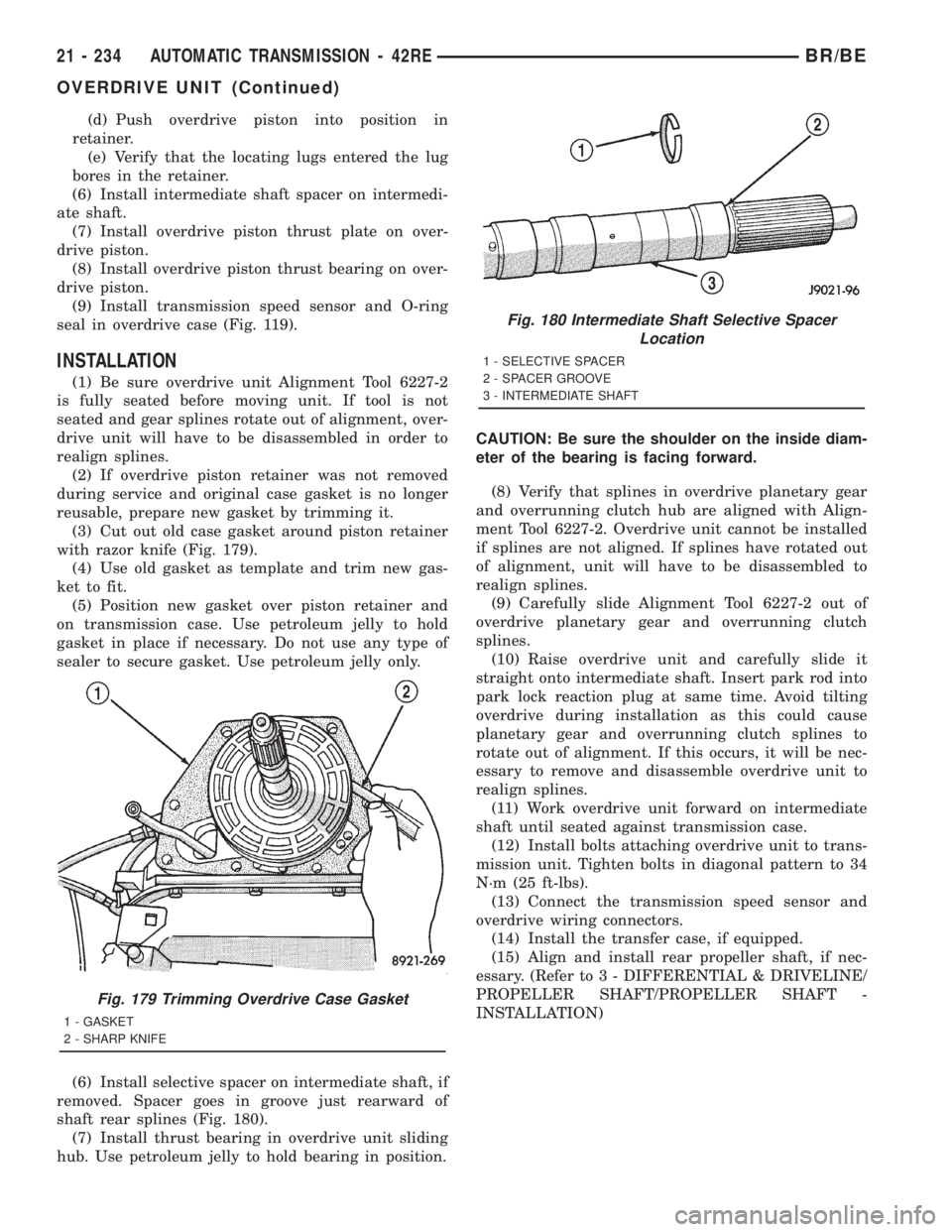
(3) Cut out old case gasket around piston retainer
with razor knife (Fig. 179).
(4) Use old gasket as template and trim new gas-
ket to fit.
(5) Position new gasket over piston retainer and
on transmission case. Use petroleum jelly to hold
gasket in place if necessary. Do not use any type of
sealer to secure gasket. Use petroleum jelly only.
(6) Install selective spacer on intermediate shaft, if
removed. Spacer goes in groove just rearward of
shaft rear splines (Fig. 180).
(7) Install thrust bearing in overdrive unit sliding
hub. Use petroleum jelly to hold bearing in position.CAUTION: Be sure the shoulder on the inside diam-
eter of the bearing is facing forward.
(8) Verify that splines in overdrive planetary gear
and overrunning clutch hub are aligned with Align-
ment Tool 6227-2. Overdrive unit cannot be installed
if splines are not aligned. If splines have rotated out
of alignment, unit will have to be disassembled to
realign splines.
(9) Carefully slide Alignment Tool 6227-2 out of
overdrive planetary gear and overrunning clutch
splines.
(10) Raise overdrive unit and carefully slide it
straight onto intermediate shaft. Insert park rod into
park lock reaction plug at same time. Avoid tilting
overdrive during installation as this could cause
planetary gear and overrunning clutch splines to
rotate out of alignment. If this occurs, it will be nec-
essary to remove and disassemble overdrive unit to
realign splines.
(11) Work overdrive unit forward on intermediate
shaft until seated against transmission case.
(12) Install bolts attaching overdrive unit to trans-
mission unit. Tighten bolts in diagonal pattern to 34
N´m (25 ft-lbs).
(13) Connect the transmission speed sensor and
overdrive wiring connectors.
(14) Install the transfer case, if equipped.
(15) Align and install rear propeller shaft, if nec-
essary. (Refer to 3 - DIFFERENTIAL & DRIVELINE/
PROPELLER SHAFT/PROPELLER SHAFT -
INSTALLATION)
Fig. 179 Trimming Overdrive Case Gasket
1 - GASKET
2 - SHARP KNIFE
Fig. 180 Intermediate Shaft Selective Spacer
Location
1 - SELECTIVE SPACER
2 - SPACER GROOVE
3 - INTERMEDIATE SHAFT
21 - 234 AUTOMATIC TRANSMISSION - 42REBR/BE
OVERDRIVE UNIT (Continued)
Page 1870 of 2889
OVERRUNNING CLUTCH
CAM/OVERDRIVE PISTON
RETAINER
DESCRIPTION
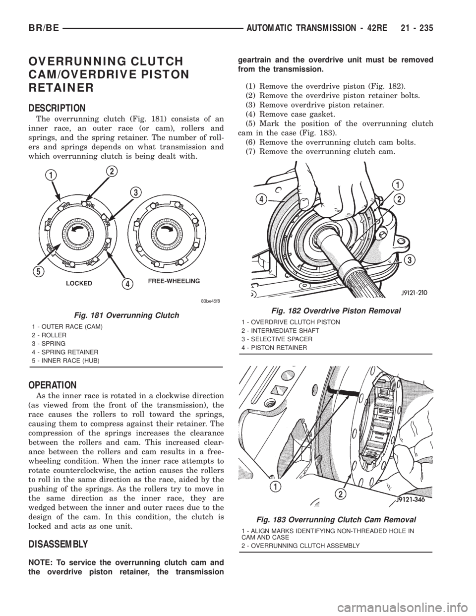
The overrunning clutch (Fig. 181) consists of an
inner race, an outer race (or cam), rollers and
springs, and the spring retainer. The number of roll-
ers and springs depends on what transmission and
which overrunning clutch is being dealt with.
OPERATION
As the inner race is rotated in a clockwise direction
(as viewed from the front of the transmission), the
race causes the rollers to roll toward the springs,
causing them to compress against their retainer. The
compression of the springs increases the clearance
between the rollers and cam. This increased clear-
ance between the rollers and cam results in a free-
wheeling condition. When the inner race attempts to
rotate counterclockwise, the action causes the rollers
to roll in the same direction as the race, aided by the
pushing of the springs. As the rollers try to move in
the same direction as the inner race, they are
wedged between the inner and outer races due to the
design of the cam. In this condition, the clutch is
locked and acts as one unit.
DISASSEMBLY
NOTE: To service the overrunning clutch cam and
the overdrive piston retainer, the transmissiongeartrain and the overdrive unit must be removed
from the transmission.
(1) Remove the overdrive piston (Fig. 182).
(2) Remove the overdrive piston retainer bolts.
(3) Remove overdrive piston retainer.
(4) Remove case gasket.
(5) Mark the position of the overrunning clutch
cam in the case (Fig. 183).
(6) Remove the overrunning clutch cam bolts.
(7) Remove the overrunning clutch cam.
Fig. 181 Overrunning Clutch
1 - OUTER RACE (CAM)
2 - ROLLER
3 - SPRING
4 - SPRING RETAINER
5 - INNER RACE (HUB)
Fig. 182 Overdrive Piston Removal
1 - OVERDRIVE CLUTCH PISTON
2 - INTERMEDIATE SHAFT
3 - SELECTIVE SPACER
4 - PISTON RETAINER
Fig. 183 Overrunning Clutch Cam Removal
1 - ALIGN MARKS IDENTIFYING NON-THREADED HOLE IN
CAM AND CASE
2 - OVERRUNNING CLUTCH ASSEMBLY
BR/BEAUTOMATIC TRANSMISSION - 42RE 21 - 235
Page 1876 of 2889
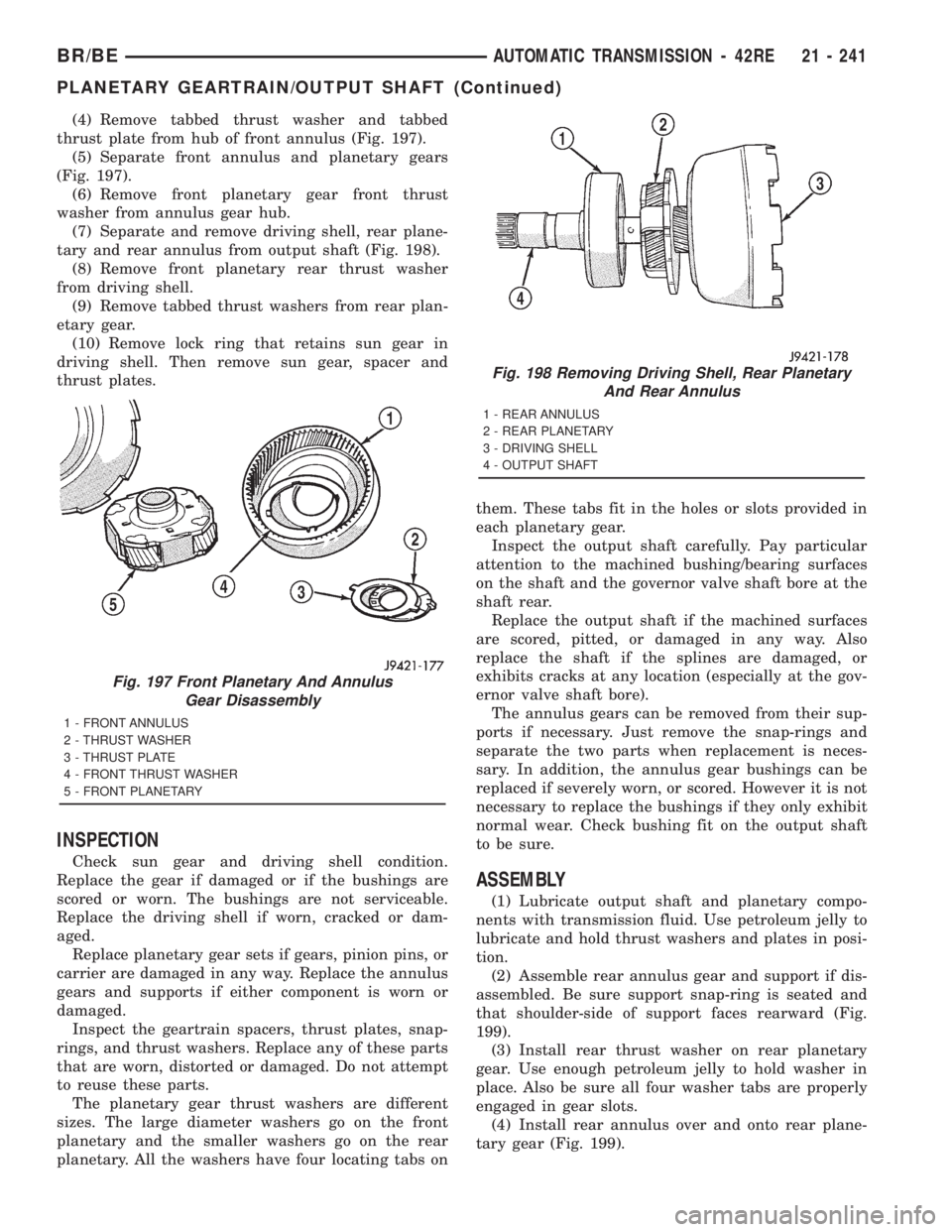
(4) Remove tabbed thrust washer and tabbed
thrust plate from hub of front annulus (Fig. 197).
(5) Separate front annulus and planetary gears
(Fig. 197).
(6) Remove front planetary gear front thrust
washer from annulus gear hub.
(7) Separate and remove driving shell, rear plane-
tary and rear annulus from output shaft (Fig. 198).
(8) Remove front planetary rear thrust washer
from driving shell.
(9) Remove tabbed thrust washers from rear plan-
etary gear.
(10) Remove lock ring that retains sun gear in
driving shell. Then remove sun gear, spacer and
thrust plates.
INSPECTION
Check sun gear and driving shell condition.
Replace the gear if damaged or if the bushings are
scored or worn. The bushings are not serviceable.
Replace the driving shell if worn, cracked or dam-
aged.
Replace planetary gear sets if gears, pinion pins, or
carrier are damaged in any way. Replace the annulus
gears and supports if either component is worn or
damaged.
Inspect the geartrain spacers, thrust plates, snap-
rings, and thrust washers. Replace any of these parts
that are worn, distorted or damaged. Do not attempt
to reuse these parts.
The planetary gear thrust washers are different
sizes. The large diameter washers go on the front
planetary and the smaller washers go on the rear
planetary. All the washers have four locating tabs onthem. These tabs fit in the holes or slots provided in
each planetary gear.
Inspect the output shaft carefully. Pay particular
attention to the machined bushing/bearing surfaces
on the shaft and the governor valve shaft bore at the
shaft rear.
Replace the output shaft if the machined surfaces
are scored, pitted, or damaged in any way. Also
replace the shaft if the splines are damaged, or
exhibits cracks at any location (especially at the gov-
ernor valve shaft bore).
The annulus gears can be removed from their sup-
ports if necessary. Just remove the snap-rings and
separate the two parts when replacement is neces-
sary. In addition, the annulus gear bushings can be
replaced if severely worn, or scored. However it is not
necessary to replace the bushings if they only exhibit
normal wear. Check bushing fit on the output shaft
to be sure.
ASSEMBLY
(1) Lubricate output shaft and planetary compo-
nents with transmission fluid. Use petroleum jelly to
lubricate and hold thrust washers and plates in posi-
tion.
(2) Assemble rear annulus gear and support if dis-
assembled. Be sure support snap-ring is seated and
that shoulder-side of support faces rearward (Fig.
199).
(3) Install rear thrust washer on rear planetary
gear. Use enough petroleum jelly to hold washer in
place. Also be sure all four washer tabs are properly
engaged in gear slots.
(4) Install rear annulus over and onto rear plane-
tary gear (Fig. 199).
Fig. 197 Front Planetary And Annulus
Gear Disassembly
1 - FRONT ANNULUS
2 - THRUST WASHER
3 - THRUST PLATE
4 - FRONT THRUST WASHER
5 - FRONT PLANETARY
Fig. 198 Removing Driving Shell, Rear Planetary
And Rear Annulus
1 - REAR ANNULUS
2 - REAR PLANETARY
3 - DRIVING SHELL
4 - OUTPUT SHAFT
BR/BEAUTOMATIC TRANSMISSION - 42RE 21 - 241
PLANETARY GEARTRAIN/OUTPUT SHAFT (Continued)
Page 1891 of 2889
TORQUE CONVERTER
DESCRIPTION
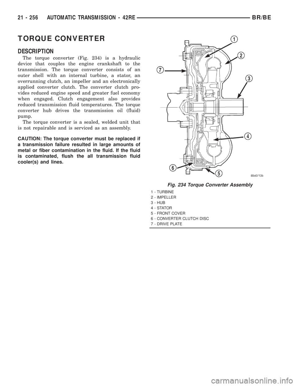
The torque converter (Fig. 234) is a hydraulic
device that couples the engine crankshaft to the
transmission. The torque converter consists of an
outer shell with an internal turbine, a stator, an
overrunning clutch, an impeller and an electronically
applied converter clutch. The converter clutch pro-
vides reduced engine speed and greater fuel economy
when engaged. Clutch engagement also provides
reduced transmission fluid temperatures. The torque
converter hub drives the transmission oil (fluid)
pump.
The torque converter is a sealed, welded unit that
is not repairable and is serviced as an assembly.
CAUTION: The torque converter must be replaced if
a transmission failure resulted in large amounts of
metal or fiber contamination in the fluid. If the fluid
is contaminated, flush the all transmission fluid
cooler(s) and lines.
Fig. 234 Torque Converter Assembly
1 - TURBINE
2 - IMPELLER
3 - HUB
4-STATOR
5 - FRONT COVER
6 - CONVERTER CLUTCH DISC
7 - DRIVE PLATE
21 - 256 AUTOMATIC TRANSMISSION - 42REBR/BE