2001 DODGE RAM battery replacement
[x] Cancel search: battery replacementPage 490 of 2889
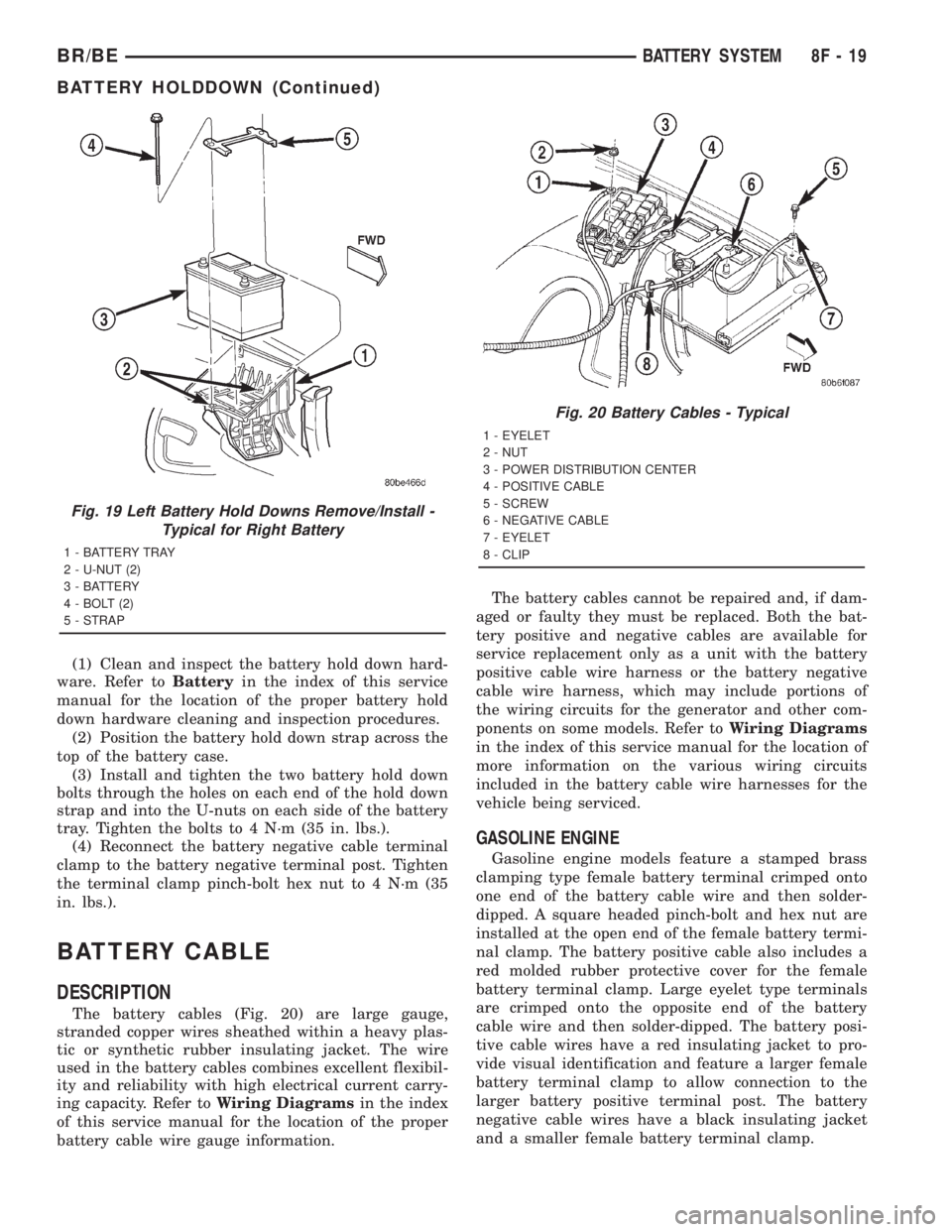
(1) Clean and inspect the battery hold down hard-
ware. Refer toBatteryin the index of this service
manual for the location of the proper battery hold
down hardware cleaning and inspection procedures.
(2) Position the battery hold down strap across the
top of the battery case.
(3) Install and tighten the two battery hold down
bolts through the holes on each end of the hold down
strap and into the U-nuts on each side of the battery
tray. Tighten the bolts to 4 N´m (35 in. lbs.).
(4) Reconnect the battery negative cable terminal
clamp to the battery negative terminal post. Tighten
the terminal clamp pinch-bolt hex nut to 4 N´m (35
in. lbs.).
BATTERY CABLE
DESCRIPTION
The battery cables (Fig. 20) are large gauge,
stranded copper wires sheathed within a heavy plas-
tic or synthetic rubber insulating jacket. The wire
used in the battery cables combines excellent flexibil-
ity and reliability with high electrical current carry-
ing capacity. Refer toWiring Diagramsin the index
of this service manual for the location of the proper
battery cable wire gauge information.The battery cables cannot be repaired and, if dam-
aged or faulty they must be replaced. Both the bat-
tery positive and negative cables are available for
service replacement only as a unit with the battery
positive cable wire harness or the battery negative
cable wire harness, which may include portions of
the wiring circuits for the generator and other com-
ponents on some models. Refer toWiring Diagrams
in the index of this service manual for the location of
more information on the various wiring circuits
included in the battery cable wire harnesses for the
vehicle being serviced.
GASOLINE ENGINE
Gasoline engine models feature a stamped brass
clamping type female battery terminal crimped onto
one end of the battery cable wire and then solder-
dipped. A square headed pinch-bolt and hex nut are
installed at the open end of the female battery termi-
nal clamp. The battery positive cable also includes a
red molded rubber protective cover for the female
battery terminal clamp. Large eyelet type terminals
are crimped onto the opposite end of the battery
cable wire and then solder-dipped. The battery posi-
tive cable wires have a red insulating jacket to pro-
vide visual identification and feature a larger female
battery terminal clamp to allow connection to the
larger battery positive terminal post. The battery
negative cable wires have a black insulating jacket
and a smaller female battery terminal clamp.
Fig. 19 Left Battery Hold Downs Remove/Install -
Typical for Right Battery
1 - BATTERY TRAY
2 - U-NUT (2)
3 - BATTERY
4 - BOLT (2)
5 - STRAP
Fig. 20 Battery Cables - Typical
1 - EYELET
2 - NUT
3 - POWER DISTRIBUTION CENTER
4 - POSITIVE CABLE
5 - SCREW
6 - NEGATIVE CABLE
7 - EYELET
8 - CLIP
BR/BEBATTERY SYSTEM 8F - 19
BATTERY HOLDDOWN (Continued)
Page 501 of 2889
Although the generators appear the same exter-
nally, different generators with different output rat-
ings are used on this vehicle. Be certain that the
replacement generator has the same output rating
and part number as the original unit. Refer to Gen-
erator Ratings in the Specifications section at the
back of this group for amperage ratings and part
numbers.
Noise emitting from the generator may be caused
by: worn, loose or defective bearings; a loose or defec-
tive drive pulley; incorrect, worn, damaged or misad-
justed fan drive belt; loose mounting bolts; a
misaligned drive pulley or a defective stator or diode.
REMOVAL
WARNING: DISCONNECT NEGATIVE CABLE FROM
BATTERY BEFORE REMOVING BATTERY OUTPUT
WIRE (B+ WIRE) FROM GENERATOR. FAILURE TO
DO SO CAN RESULT IN INJURY OR DAMAGE TO
ELECTRICAL SYSTEM.
(1) Disconnect negative battery cable at battery.
Diesel Engines: Disconnect both negative battery
cables at both batteries.
(2) Remove generator drive belt. Refer to 7, Cool-
ing System for procedure.
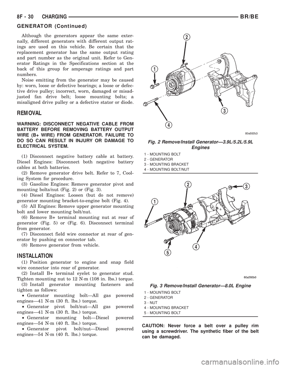
(3) Gasoline Engines: Remove generator pivot and
mounting bolts/nut (Fig. 2) or (Fig. 3).
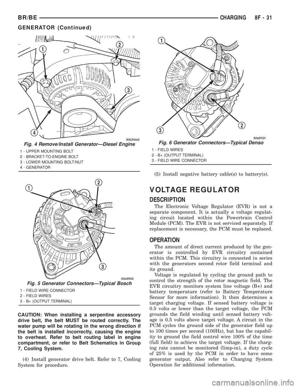
(4) Diesel Engines: Loosen (but do not remove)
generator mounting bracket-to-engine bolt (Fig. 4).
(5) All Engines: Remove upper generator mounting
bolt and lower mounting bolt/nut.
(6) Remove B+ terminal mounting nut at rear of
generator (Fig. 5) or (Fig. 6). Disconnect terminal
from generator.
(7) Disconnect field wire connector at rear of gen-
erator by pushing on connector tab.
(8) Remove generator from vehicle.
INSTALLATION
(1) Position generator to engine and snap field
wire connector into rear of generator.
(2) Install B+ terminal eyelet to generator stud.
Tighten mounting nut to 12 N´m (108 in. lbs.) torque.
(3) Install generator mounting fasteners and
tighten as follows:
²Generator mounting boltÐAll gas powered
enginesÐ41 N´m (30 ft. lbs.) torque.
²Generator pivot bolt/nutÐAll gas powered
enginesÐ41 N´m (30 ft. lbs.) torque.
²Generator mounting boltÐDiesel powered
enginesÐ54 N´m (40 ft. lbs.) torque.
²Generator pivot bolt/nutÐDiesel powered
enginesÐ54 N´m (40 ft. lbs.) torque.CAUTION: Never force a belt over a pulley rim
using a screwdriver. The synthetic fiber of the belt
can be damaged.
Fig. 2 Remove/Install GeneratorÐ3.9L/5.2L/5.9L
Engines
1 - MOUNTING BOLT
2 - GENERATOR
3 - MOUNTING BRACKET
4 - MOUNTING BOLT/NUT
Fig. 3 Remove/Install GeneratorÐ8.0L Engine
1 - MOUNTING BOLT
2 - GENERATOR
3 - NUT
4 - MOUNTING BRACKET
5 - MOUNTING BOLT
8F - 30 CHARGINGBR/BE
GENERATOR (Continued)
Page 502 of 2889
CAUTION: When installing a serpentine accessory
drive belt, the belt MUST be routed correctly. The
water pump will be rotating in the wrong direction if
the belt is installed incorrectly, causing the engine
to overheat. Refer to belt routing label in engine
compartment, or refer to Belt Schematics in Group
7, Cooling System.
(4) Install generator drive belt. Refer to 7, Cooling
System for procedure.(5) Install negative battery cable(s) to battery(s).
VOLTAGE REGULATOR
DESCRIPTION
The Electronic Voltage Regulator (EVR) is not a
separate component. It is actually a voltage regulat-
ing circuit located within the Powertrain Control
Module (PCM). The EVR is not serviced separately. If
replacement is necessary, the PCM must be replaced.
OPERATION
The amount of direct current produced by the gen-
erator is controlled by EVR circuitry contained
within the PCM. This circuitry is connected in series
with the generators second rotor field terminal and
its ground.
Voltage is regulated by cycling the ground path to
control the strength of the rotor magnetic field. The
EVR circuitry monitors system line voltage (B+) and
battery temperature (refer to Battery Temperature
Sensor for more information). It then determines a
target charging voltage. If sensed battery voltage is
0.5 volts or lower than the target voltage, the PCM
grounds the field winding until sensed battery volt-
age is 0.5 volts above target voltage. A circuit in the
PCM cycles the ground side of the generator field up
to 100 times per second (100Hz), but has the capabil-
ity to ground the field control wire 100% of the time
(full field) to achieve the target voltage. If the charg-
ing rate cannot be monitored (limp-in), a duty cycle
of 25% is used by the PCM in order to have some
generator output. Also refer to Charging System
Operation for additional information.
Fig. 4 Remove/Install GeneratorÐDiesel Engine
1 - UPPER MOUNTING BOLT
2 - BRACKET-TO-ENGINE BOLT
3 - LOWER MOUNTING BOLT/NUT
4 - GENERATOR
Fig. 5 Generator ConnectorsÐTypical Bosch
1 - FIELD WIRE CONNECTOR
2 - FIELD WIRES
3 - B+ (OUTPUT TERMINAL)
Fig. 6 Generator ConnectorsÐTypical Denso
1 - FIELD WIRES
2 - B+ (OUTPUT TERMINAL)
3 - FIELD WIRE CONNECTOR
BR/BECHARGING 8F - 31
GENERATOR (Continued)
Page 524 of 2889
Manual for additional diagnosis and testing proce-
dures. If not OK, replace the faulty heated seat
switch.
Heated Seat Switch Continuity
Switch PositionContinuity
BetweenResistance
Neutral 4 & 6 2.2 Kilohms
Low 4 & 6 510 Ohms
High 4 & 6 33 Ohms
(8) Replace the inoperative heated seat switch
with a known good unit and test the operation of the
switch indicator lamps. If OK, discard the faulty
heated seat switch. If not OK, refer toHeated Seat
Modulein Electronic Control Modules for the loca-
tion of the proper heated seat module diagnosis and
testing procedures. Also refer to the Body Diagnostic
Manual for additional diagnosis and testing proce-
dures.
REMOVAL
Both heated seat switches and the heated seat
switch bezel are available individually for service
replacement.
(1) Disconnect and isolate the battery negative
cable.
(2) Remove the cluster bezel from the instrument
panel. Refer toCluster Bezelin the index of this
service manual for the location of the proper cluster
bezel removal procedures.
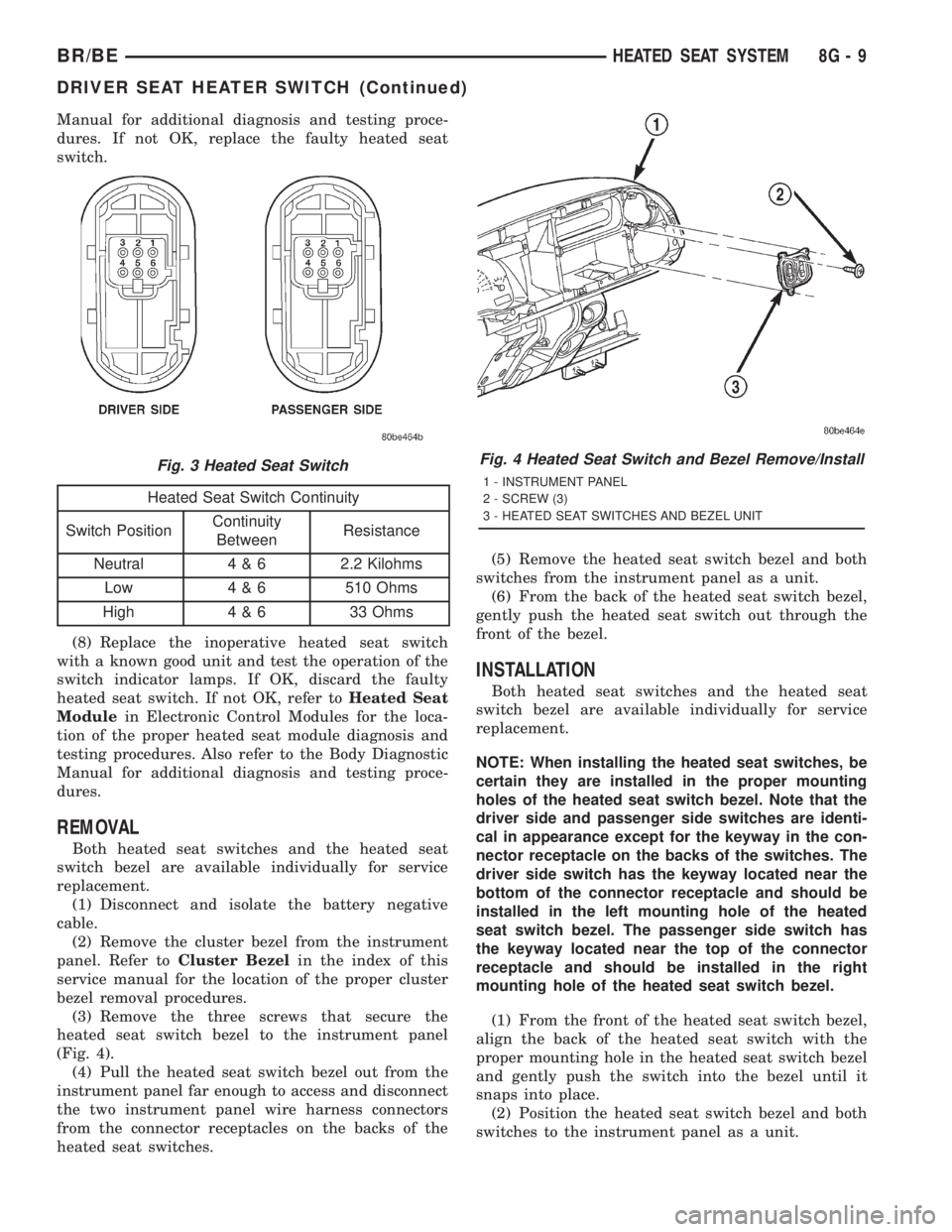
(3) Remove the three screws that secure the
heated seat switch bezel to the instrument panel
(Fig. 4).
(4) Pull the heated seat switch bezel out from the
instrument panel far enough to access and disconnect
the two instrument panel wire harness connectors
from the connector receptacles on the backs of the
heated seat switches.(5) Remove the heated seat switch bezel and both
switches from the instrument panel as a unit.
(6) From the back of the heated seat switch bezel,
gently push the heated seat switch out through the
front of the bezel.
INSTALLATION
Both heated seat switches and the heated seat
switch bezel are available individually for service
replacement.
NOTE: When installing the heated seat switches, be
certain they are installed in the proper mounting
holes of the heated seat switch bezel. Note that the
driver side and passenger side switches are identi-
cal in appearance except for the keyway in the con-
nector receptacle on the backs of the switches. The
driver side switch has the keyway located near the
bottom of the connector receptacle and should be
installed in the left mounting hole of the heated
seat switch bezel. The passenger side switch has
the keyway located near the top of the connector
receptacle and should be installed in the right
mounting hole of the heated seat switch bezel.
(1) From the front of the heated seat switch bezel,
align the back of the heated seat switch with the
proper mounting hole in the heated seat switch bezel
and gently push the switch into the bezel until it
snaps into place.
(2) Position the heated seat switch bezel and both
switches to the instrument panel as a unit.
Fig. 3 Heated Seat SwitchFig. 4 Heated Seat Switch and Bezel Remove/Install
1 - INSTRUMENT PANEL
2 - SCREW (3)
3 - HEATED SEAT SWITCHES AND BEZEL UNIT
BR/BEHEATED SEAT SYSTEM 8G - 9
DRIVER SEAT HEATER SWITCH (Continued)
Page 530 of 2889
Clusterin the index of this service manual for the
proper cluster illumination lamps diagnosis and test-
ing procedures. If the problem being diagnosed
involves inoperative heated seat switch indicator
lamps and the heated seat elements do not heat,
refer to Step 4. If the problem being diagnosed
involves inoperative heated seat switch indicator
lamps and the heated seat elements do heat, go to
Step 8. If the problem being diagnosed involves a
heated seat switch indicator lamp that remains illu-
minated after the heated seat has been turned Off,
refer toHeated Seat Modulein Electronic Control
Modules for the location of the proper heated seat
module diagnosis and testing procedures. Also refer
to the Body Diagnostic Manual for additional diagno-
sis and testing procedures.
(2) Disconnect and isolate the battery negative
cable. Remove the heated seat switch and bezel unit
from the instrument panel. Disconnect the instru-
ment panel wire harness connector from the connec-
tor receptacle on the back of the heated seat switch
to be tested. Check for continuity between the ground
circuit cavity of the instrument panel wire harness
connector for the heated seat switch and a good
ground. There should be continuity. If OK, go to Step
3. If not OK, repair the open ground circuit to ground
as required.
(3) Reconnect the battery negative cable. Turn the
park lamps on with the headlamp switch. Rotate the
panel lamps dimmer thumbwheel on the headlamp
switch upward to just before the interior lamps
detent. Check for battery voltage at the fused panel
lamps dimmer switch signal circuit cavity of the
instrument panel wire harness connector for the
heated seat switch. If OK, replace the faulty heated
seat switch. If not OK, repair the open fused panel
lamps dimmer switch signal circuit to the fuse in the
Junction Block (JB) as required.
(4) Check the fused ignition switch output (run)
fuse in the Junction Block (JB). If OK, go to Step 5.
If not OK, repair the shorted circuit or component as
required and replace the faulty fuse.
(5) Turn the ignition switch to the On position.
Check for battery voltage at the fused ignition switch
output (run) fuse in the JB. If OK, go to Step 6. If
not OK, repair the open fused ignition switch output
(run) circuit to the ignition switch as required.
(6) Disconnect and isolate the battery negative
cable. Remove the heated seat switch and bezel unit
from the instrument panel. Disconnect the instru-
ment panel wire harness connector from the connec-
tor receptacle on the back of the heated seat switch
to be tested. Reconnect the battery negative cable.
Turn the ignition switch to the On position. Check
for battery voltage at the fused ignition switch out-
put (run) circuit cavity of the instrument panel wireharness connector for the heated seat switch. If OK,
go to Step 7. If not OK, repair the open fused ignition
switch output (run) circuit to the JB fuse as required.
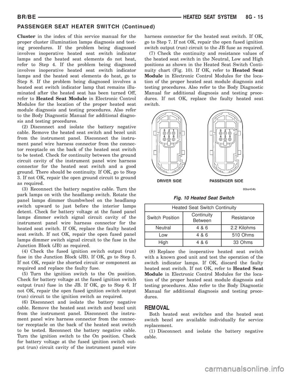
(7) Check the continuity and resistance values of
the heated seat switch in the Neutral, Low and High
positions as shown in the Heated Seat Switch Conti-
nuity chart (Fig. 10). If OK, refer toHeated Seat
Modulein Electronic Control Modules for the loca-
tion of the proper heated seat module diagnosis and
testing procedures. Also refer to the Body Diagnostic
Manual for additional diagnosis and testing proce-
dures. If not OK, replace the faulty heated seat
switch.
Heated Seat Switch Continuity
Switch PositionContinuity
BetweenResistance
Neutral 4 & 6 2.2 Kilohms
Low 4 & 6 510 Ohms
High 4 & 6 33 Ohms
(8) Replace the inoperative heated seat switch
with a known good unit and test the operation of the
switch indicator lamps. If OK, discard the faulty
heated seat switch. If not OK, refer toHeated Seat
Modulein Electronic Control Modules for the loca-
tion of the proper heated seat module diagnosis and
testing procedures. Also refer to the Body Diagnostic
Manual for additional diagnosis and testing proce-
dures.
REMOVAL
Both heated seat switches and the heated seat
switch bezel are available individually for service
replacement.
(1) Disconnect and isolate the battery negative
cable.
Fig. 10 Heated Seat Switch
BR/BEHEATED SEAT SYSTEM 8G - 15
PASSENGER SEAT HEATER SWITCH (Continued)
Page 531 of 2889
(2) Remove the cluster bezel from the instrument
panel. Refer toCluster Bezelin the index of this
service manual for the location of the proper cluster
bezel removal procedures.
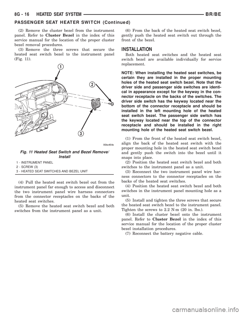
(3) Remove the three screws that secure the
heated seat switch bezel to the instrument panel
(Fig. 11).
(4) Pull the heated seat switch bezel out from the
instrument panel far enough to access and disconnect
the two instrument panel wire harness connectors
from the connector receptacles on the backs of the
heated seat switches.
(5) Remove the heated seat switch bezel and both
switches from the instrument panel as a unit.(6) From the back of the heated seat switch bezel,
gently push the heated seat switch out through the
front of the bezel.
INSTALLATION
Both heated seat switches and the heated seat
switch bezel are available individually for service
replacement.
NOTE: When installing the heated seat switches, be
certain they are installed in the proper mounting
holes of the heated seat switch bezel. Note that the
driver side and passenger side switches are identi-
cal in appearance except for the keyway in the con-
nector receptacle on the backs of the switches. The
driver side switch has the keyway located near the
bottom of the connector receptacle and should be
installed in the left mounting hole of the heated
seat switch bezel. The passenger side switch has
the keyway located near the top of the connector
receptacle and should be installed in the right
mounting hole of the heated seat switch bezel.
(1) From the front of the heated seat switch bezel,
align the back of the heated seat switch with the
proper mounting hole in the heated seat switch bezel
and gently push the switch into the bezel until it
snaps into place.
(2) Position the heated seat switch bezel and both
switches to the instrument panel as a unit.
(3) Reconnect the two instrument panel wire har-
ness connectors to the connector receptacles on the
backs of the heated seat switches.
(4) Position the heated seat switch bezel and both
switches in the instrument panel mounting hole as a
unit.
(5) Install and tighten the three screws that secure
the heated seat switch bezel to the instrument panel.
Tighten the screws to 2.2 N´m (20 in. lbs.).
(6) Install the cluster bezel onto the instrument
panel. Refer toCluster Bezelin the index of this
service manual for the location of the proper cluster
bezel installation procedures.
(7) Reconnect the battery negative cable.
Fig. 11 Heated Seat Switch and Bezel Remove/
Install
1 - INSTRUMENT PANEL
2 - SCREW (3)
3 - HEATED SEAT SWITCHES AND BEZEL UNIT
8G - 16 HEATED SEAT SYSTEMBR/BE
PASSENGER SEAT HEATER SWITCH (Continued)
Page 562 of 2889
²Check Gauges Indicator
²Cruise Indicator (Odometer VFD)
²Four-Wheel Drive Indicator
²High Beam Indicator
²Low Fuel Indicator
²Washer Fluid Indicator
²Malfunction Indicator Lamp (MIL)
²Overdrive-Off Indicator
²Seatbelt Indicator
²Service Reminder Indicator (SRI)
²Transmission Overtemp Indicator
²Turn Signal (Right and Left) Indicators
²Upshift Indicator
²Wait-To-Start Indicator (Diesel Only)
²Water-In-Fuel Indicator (Diesel Only)
Some of these indicators are either programmable
or automatically configured when the EMIC is con-
nected to the vehicle electrical system. This feature
allows those indicators to be activated or deactivated
for compatibility with certain optional equipment.
The EMIC also includes a provision for mounting the
automatic transmission gear selector indicator in the
lower right corner of the cluster. The spring-loaded,
cable driven, mechanical gear selector indicator gives
an indication of the transmission gear that has been
selected with the automatic transmission gear selec-
tor lever. The gear selector indicator pointer is easily
visible through an opening provided in the front of
the cluster overlay, and is also lighted by the cluster
illumination lamps for visibility at night. Models
equipped with a manual transmission have a block-
out plate installed in place of the gear selector indi-
cator.
Cluster illumination is accomplished by adjustable
incandescent back lighting, which illuminates the
gauges for visibility when the exterior lighting is
turned on. The EMIC high beam indicator, turn sig-
nal indicators, and wait-to-start indicator are also
illuminated by dedicated incandescent bulbs. The
remaining indicators in the EMIC are each illumi-
nated by a dedicated Light Emitting Diode (LED)
that is soldered onto the electronic circuit board.
Each of the incandescent bulbs is secured by an inte-
gral bulb holder to the electronic circuit board from
the back of the cluster housing.
Hard wired circuitry connects the EMIC to the
electrical system of the vehicle. These hard wired cir-
cuits are integral to several wire harnesses, which
are routed throughout the vehicle and retained by
many different methods. These circuits may be con-
nected to each other, to the vehicle electrical system
and to the EMIC through the use of a combination of
soldered splices, splice block connectors, and many
different types of wire harness terminal connectors
and insulators. Refer to the appropriate wiring infor-
mation. The wiring information includes wiring dia-grams, proper wire and connector repair procedures,
further details on wire harness routing and reten-
tion, as well as pin-out and location views for the
various wire harness connectors, splices and grounds.
The EMIC modules for this model are serviced only
as complete units. The EMIC module cannot be
adjusted or repaired. If a gauge, an LED indicator,
the VFD, the electronic circuit board, the circuit
board hardware, the cluster overlay, or the EMIC
housing are damaged or faulty, the entire EMIC mod-
ule must be replaced. The cluster lens and hood unit,
the rear cluster housing cover, the automatic trans-
mission gear selector indicator, and the incandescent
lamp bulbs with holders are available for individual
service replacement.
OPERATION
The ElectroMechanical Instrument Cluster (EMIC)
is designed to allow the vehicle operator to monitor
the conditions of many of the vehicle components and
operating systems. The gauges and indicators in the
EMIC provide valuable information about the various
standard and optional powertrains, fuel and emis-
sions systems, cooling systems, lighting systems,
safety systems and many other convenience items.
The EMIC is installed in the instrument panel so
that all of these monitors can be easily viewed by the
vehicle operator when driving, while still allowing
relative ease of access for service. The microproces-
sor-based EMIC hardware and software uses various
inputs to control the gauges and indicators visible on
the face of the cluster. Some of these inputs are hard
wired, but most are in the form of electronic mes-
sages that are transmitted by other electronic mod-
ules over the Chrysler Collision Detection (CCD) data
bus network. (Refer to 8 - ELECTRICAL/ELEC-
TRONIC CONTROL MODULES/COMMUNICATION
- OPERATION).
The EMIC microprocessor smooths the input data
using algorithms to provide gauge readings that are
accurate, stable and responsive to operating condi-
tions. These algorithms are designed to provide
gauge readings during normal operation that are con-
sistent with customer expectations. However, when
abnormal conditions exist, such as low/high battery
voltage, low oil pressure, or high coolant tempera-
ture, the algorithm drives the gauge pointer to an
extreme position and the microprocessor turns on the
Check Gauges indicator to provide a distinct visual
indication of a problem to the vehicle operator. The
instrument cluster circuitry may also generate a
hard wired chime tone request to the Central Timer
Module (CTM) when it monitors certain conditions or
inputs, in order to provide the vehicle operator with
an audible alert.
BR/BEINSTRUMENT CLUSTER 8J - 3
INSTRUMENT CLUSTER (Continued)
Page 572 of 2889
ASSEMBLY
WARNING: ON VEHICLES EQUIPPED WITH AIR-
BAGS, DISABLE THE AIRBAG SYSTEM BEFORE
ATTEMPTING ANY STEERING WHEEL, STEERING
COLUMN, OR INSTRUMENT PANEL COMPONENT
DIAGNOSIS OR SERVICE. DISCONNECT AND ISO-
LATE THE BATTERY NEGATIVE (GROUND) CABLE,
THEN WAIT TWO MINUTES FOR THE AIRBAG SYS-
TEM CAPACITOR TO DISCHARGE BEFORE PER-
FORMING FURTHER DIAGNOSIS OR SERVICE. THIS
IS THE ONLY SURE WAY TO DISABLE THE AIRBAG
SYSTEM. FAILURE TO TAKE THE PROPER PRE-
CAUTIONS COULD RESULT IN ACCIDENTAL AIR-
BAG DEPLOYMENT AND POSSIBLE PERSONAL
INJURY.
GEAR SELECTOR INDICATOR
(1) Position the gear selector indicator mechanism
and cable unit into the instrument panel cluster
opening.
(2) Route the cable through the instrument panel
and under the steering column to the PRNDL driver
lever on the left side of the steering column.
(3) Squeeze the sides of the plastic adjuster and
bracket unit and engage the tabs that secure it with
the sides of the steering column window.
(4) Engage the loop end of the gear selector indi-
cator cable onto the PRNDL driver lever on the left
side of the steering column (Fig. 4).
(5) Reinstall the instrument cluster onto the
instrument panel. (Refer to 8 - ELECTRICAL/IN-
STRUMENT CLUSTER - INSTALLATION).
(6) Confirm proper operation of the gear selector
indicator. Calibrate the indicator, if required. (Refer
to 19 - STEERING/COLUMN - INSTALLATION).
(7) Reinstall the steering column opening cover
onto the instrument panel. (Refer to 23 - BODY/IN-
STRUMENT PANEL/STEERING COLUMN OPEN-
ING COVER - INSTALLATION).
(8) Reconnect the battery negative cable.
CLUSTER BULB
This procedure applies to each of the incandescent
cluster illumination lamp or indicator lamp bulb and
bulb holder units. However, the illumination lamps
and the indicator lamps use different bulb and bulb
holder unit sizes. They must never be interchanged.
CAUTION: Be certain that any bulb and bulb holder
unit removed from the cluster electronic circuit
board is reinstalled in the correct position. Always
use the correct bulb size and type for replacement.
An incorrect bulb size or type may overheat and
cause damage to the instrument cluster, the elec-
tronic circuit board and/or the gauges.(1) Insert the bulb and bulb holder unit straight
into the correct bulb mounting hole in the cluster
electronic circuit board (Fig. 5).
(2) With the bulb holder fully seated against the
cluster electronic circuit board, turn the bulb holder
clockwise about sixty degrees to lock it into place.
(3) Reinstall the instrument cluster onto the
instrument panel. (Refer to 8 - ELECTRICAL/IN-
STRUMENT CLUSTER - INSTALLATION).
(4) Reconnect the battery negative cable.
CLUSTER LENS AND HOOD
CAUTION: Do not touch the face of the gauge over-
lay or the back of the cluster lens with your finger.
It will leave a permanent finger print.
(1) Align the cluster lens and hood unit with the
cluster housing. Be certain that the odometer/trip
odometer switch button is installed through the
clearance hole in the lens (Fig. 6).
(2) Install and tighten the seven screws that
secure the lens and hood unit to the cluster housing.
Tighten the screws to 2.2 N´m (20 in. lbs.).
(3) Reinstall the instrument cluster onto the
instrument panel. (Refer to 8 - ELECTRICAL/IN-
STRUMENT CLUSTER - INSTALLATION).
(4) Reconnect the battery negative cable.
CLUSTER HOUSING REAR COVER
(1) Position the rear cover onto the back of the
cluster housing (Fig. 7).
(2) Install and tighten the six screws that secure
the rear cover to the back of the cluster housing.
Tighten the screws to 2.2 N´m (20 in. lbs.).
(3) Reinstall the instrument cluster onto the
instrument panel. (Refer to 8 - ELECTRICAL/IN-
STRUMENT CLUSTER - INSTALLATION).
(4) Reconnect the battery negative cable.
CLUSTER HOUSING
(1) Assemble the rear cover onto the cluster hous-
ing. Refer to CLUSTER HOUSING REAR COVER .
(2) Assemble the lens and hood unit onto the clus-
ter housing. Refer to CLUSTER LENS AND HOOD .
(3) Reinstall the instrument cluster onto the
instrument panel. (Refer to 8 - ELECTRICAL/IN-
STRUMENT CLUSTER - INSTALLATION).
(4) Reconnect the battery negative cable.
BR/BEINSTRUMENT CLUSTER 8J - 13
INSTRUMENT CLUSTER (Continued)