2001 DODGE RAM battery replacement
[x] Cancel search: battery replacementPage 1344 of 2889
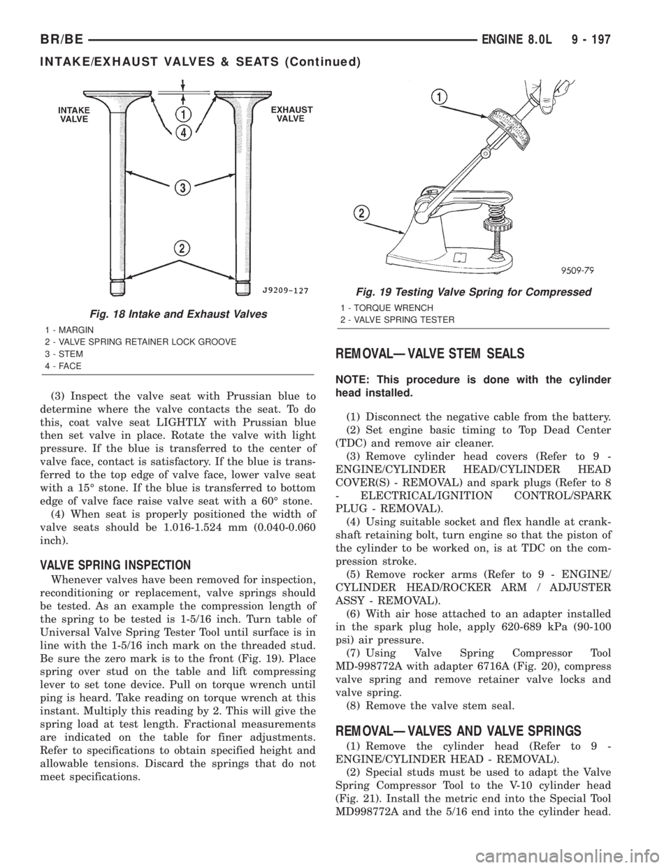
(3) Inspect the valve seat with Prussian blue to
determine where the valve contacts the seat. To do
this, coat valve seat LIGHTLY with Prussian blue
then set valve in place. Rotate the valve with light
pressure. If the blue is transferred to the center of
valve face, contact is satisfactory. If the blue is trans-
ferred to the top edge of valve face, lower valve seat
with a 15É stone. If the blue is transferred to bottom
edge of valve face raise valve seat with a 60É stone.
(4) When seat is properly positioned the width of
valve seats should be 1.016-1.524 mm (0.040-0.060
inch).
VALVE SPRING INSPECTION
Whenever valves have been removed for inspection,
reconditioning or replacement, valve springs should
be tested. As an example the compression length of
the spring to be tested is 1-5/16 inch. Turn table of
Universal Valve Spring Tester Tool until surface is in
line with the 1-5/16 inch mark on the threaded stud.
Be sure the zero mark is to the front (Fig. 19). Place
spring over stud on the table and lift compressing
lever to set tone device. Pull on torque wrench until
ping is heard. Take reading on torque wrench at this
instant. Multiply this reading by 2. This will give the
spring load at test length. Fractional measurements
are indicated on the table for finer adjustments.
Refer to specifications to obtain specified height and
allowable tensions. Discard the springs that do not
meet specifications.
REMOVALÐVALVE STEM SEALS
NOTE: This procedure is done with the cylinder
head installed.
(1) Disconnect the negative cable from the battery.
(2) Set engine basic timing to Top Dead Center
(TDC) and remove air cleaner.
(3) Remove cylinder head covers (Refer to 9 -
ENGINE/CYLINDER HEAD/CYLINDER HEAD
COVER(S) - REMOVAL) and spark plugs (Refer to 8
- ELECTRICAL/IGNITION CONTROL/SPARK
PLUG - REMOVAL).
(4) Using suitable socket and flex handle at crank-
shaft retaining bolt, turn engine so that the piston of
the cylinder to be worked on, is at TDC on the com-
pression stroke.
(5) Remove rocker arms (Refer to 9 - ENGINE/
CYLINDER HEAD/ROCKER ARM / ADJUSTER
ASSY - REMOVAL).
(6) With air hose attached to an adapter installed
in the spark plug hole, apply 620-689 kPa (90-100
psi) air pressure.
(7) Using Valve Spring Compressor Tool
MD-998772A with adapter 6716A (Fig. 20), compress
valve spring and remove retainer valve locks and
valve spring.
(8) Remove the valve stem seal.
REMOVALÐVALVES AND VALVE SPRINGS
(1) Remove the cylinder head (Refer to 9 -
ENGINE/CYLINDER HEAD - REMOVAL).
(2) Special studs must be used to adapt the Valve
Spring Compressor Tool to the V-10 cylinder head
(Fig. 21). Install the metric end into the Special Tool
MD998772A and the 5/16 end into the cylinder head.
Fig. 18 Intake and Exhaust Valves
1 - MARGIN
2 - VALVE SPRING RETAINER LOCK GROOVE
3 - STEM
4-FACE
Fig. 19 Testing Valve Spring for Compressed
1 - TORQUE WRENCH
2 - VALVE SPRING TESTER
BR/BEENGINE 8.0L 9 - 197
INTAKE/EXHAUST VALVES & SEATS (Continued)
Page 1427 of 2889
CAUTION: The seal lip and the sealing surface on
the crankshaft must be free from all oil residue to
prevent seal leaks. The crankshaft and seal sur-
faces must be completely dry when the seal is
installed. Use a soap and water solution on outside
diameter of seal to ease assembly.
(4) Make sure the provided seal pilot is installed
into the new crankshaft seal. Use the alignment/in-
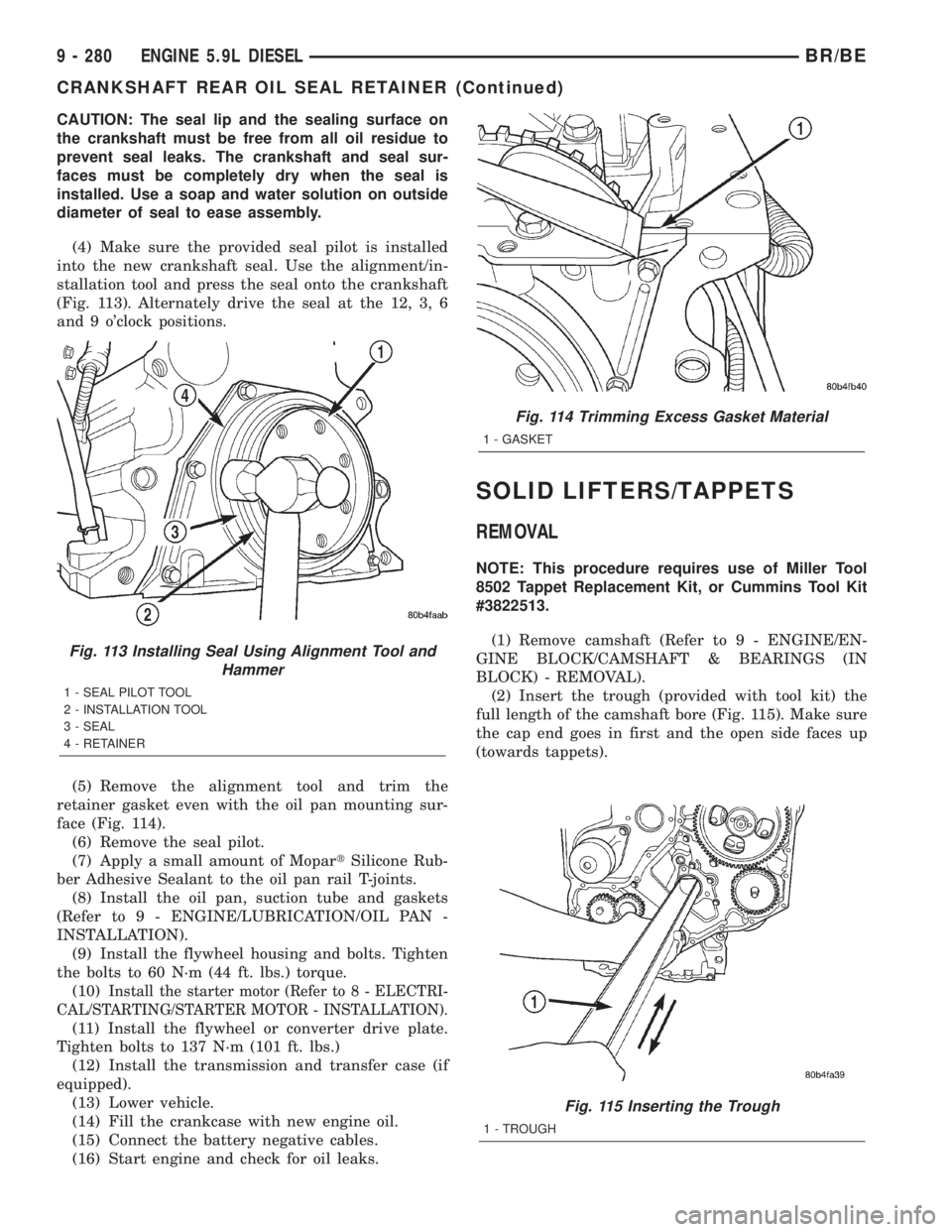
stallation tool and press the seal onto the crankshaft
(Fig. 113). Alternately drive the seal at the 12, 3, 6
and 9 o'clock positions.
(5) Remove the alignment tool and trim the
retainer gasket even with the oil pan mounting sur-
face (Fig. 114).
(6) Remove the seal pilot.
(7) Apply a small amount of MopartSilicone Rub-
ber Adhesive Sealant to the oil pan rail T-joints.
(8) Install the oil pan, suction tube and gaskets
(Refer to 9 - ENGINE/LUBRICATION/OIL PAN -
INSTALLATION).
(9) Install the flywheel housing and bolts. Tighten
the bolts to 60 N´m (44 ft. lbs.) torque.
(10)
Install the starter motor (Refer to 8 - ELECTRI-
CAL/STARTING/STARTER MOTOR - INSTALLATION).
(11) Install the flywheel or converter drive plate.
Tighten bolts to 137 N´m (101 ft. lbs.)
(12) Install the transmission and transfer case (if
equipped).
(13) Lower vehicle.
(14) Fill the crankcase with new engine oil.
(15) Connect the battery negative cables.
(16) Start engine and check for oil leaks.
SOLID LIFTERS/TAPPETS
REMOVAL
NOTE: This procedure requires use of Miller Tool
8502 Tappet Replacement Kit, or Cummins Tool Kit
#3822513.
(1) Remove camshaft (Refer to 9 - ENGINE/EN-
GINE BLOCK/CAMSHAFT & BEARINGS (IN
BLOCK) - REMOVAL).
(2) Insert the trough (provided with tool kit) the
full length of the camshaft bore (Fig. 115). Make sure
the cap end goes in first and the open side faces up
(towards tappets).
Fig. 115 Inserting the Trough
1 - TROUGH
Fig. 113 Installing Seal Using Alignment Tool and
Hammer
1 - SEAL PILOT TOOL
2 - INSTALLATION TOOL
3 - SEAL
4 - RETAINER
Fig. 114 Trimming Excess Gasket Material
1 - GASKET
9 - 280 ENGINE 5.9L DIESELBR/BE
CRANKSHAFT REAR OIL SEAL RETAINER (Continued)
Page 1512 of 2889
(b) Type 2: Separate and unlatch 2 small arms
on end of clip (Fig. 47) and swing away from fuel
line.
(c) Slide latch clip toward fuel rail while lifting
with screwdriver.
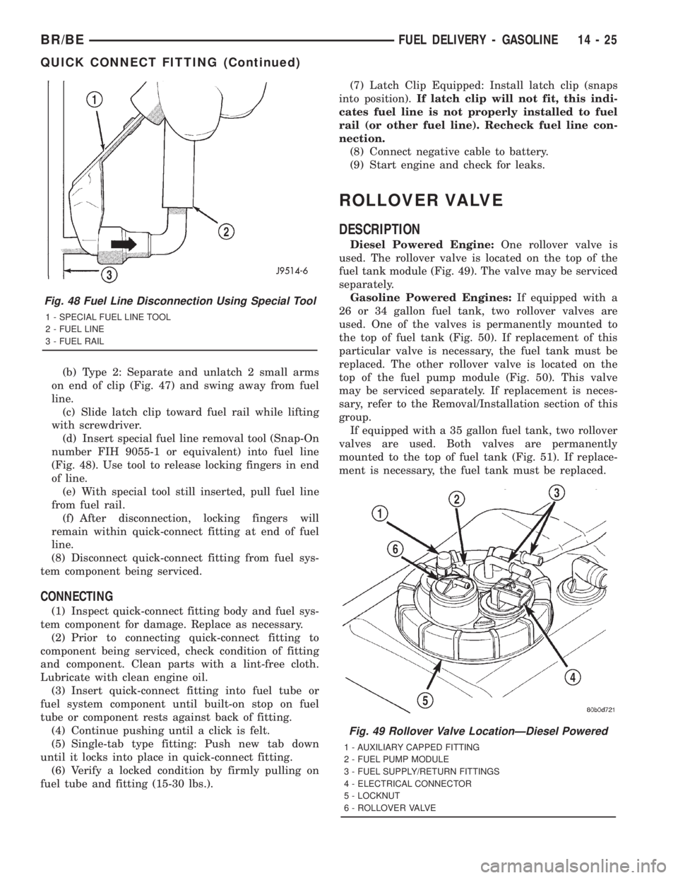
(d) Insert special fuel line removal tool (Snap-On
number FIH 9055-1 or equivalent) into fuel line
(Fig. 48). Use tool to release locking fingers in end
of line.
(e) With special tool still inserted, pull fuel line
from fuel rail.
(f) After disconnection, locking fingers will
remain within quick-connect fitting at end of fuel
line.
(8) Disconnect quick-connect fitting from fuel sys-
tem component being serviced.
CONNECTING
(1) Inspect quick-connect fitting body and fuel sys-
tem component for damage. Replace as necessary.
(2) Prior to connecting quick-connect fitting to
component being serviced, check condition of fitting
and component. Clean parts with a lint-free cloth.
Lubricate with clean engine oil.
(3) Insert quick-connect fitting into fuel tube or
fuel system component until built-on stop on fuel
tube or component rests against back of fitting.
(4) Continue pushing until a click is felt.
(5) Single-tab type fitting: Push new tab down
until it locks into place in quick-connect fitting.
(6) Verify a locked condition by firmly pulling on
fuel tube and fitting (15-30 lbs.).(7) Latch Clip Equipped: Install latch clip (snaps
into position).If latch clip will not fit, this indi-
cates fuel line is not properly installed to fuel
rail (or other fuel line). Recheck fuel line con-
nection.
(8) Connect negative cable to battery.
(9) Start engine and check for leaks.
ROLLOVER VALVE
DESCRIPTION
Diesel Powered Engine:One rollover valve is
used. The rollover valve is located on the top of the
fuel tank module (Fig. 49). The valve may be serviced
separately.
Gasoline Powered Engines:If equipped with a
26 or 34 gallon fuel tank, two rollover valves are
used. One of the valves is permanently mounted to
the top of fuel tank (Fig. 50). If replacement of this
particular valve is necessary, the fuel tank must be
replaced. The other rollover valve is located on the
top of the fuel pump module (Fig. 50). This valve
may be serviced separately. If replacement is neces-
sary, refer to the Removal/Installation section of this
group.
If equipped with a 35 gallon fuel tank, two rollover
valves are used. Both valves are permanently
mounted to the top of fuel tank (Fig. 51). If replace-
ment is necessary, the fuel tank must be replaced.
Fig. 48 Fuel Line Disconnection Using Special Tool
1 - SPECIAL FUEL LINE TOOL
2 - FUEL LINE
3 - FUEL RAIL
Fig. 49 Rollover Valve LocationÐDiesel Powered
1 - AUXILIARY CAPPED FITTING
2 - FUEL PUMP MODULE
3 - FUEL SUPPLY/RETURN FITTINGS
4 - ELECTRICAL CONNECTOR
5 - LOCKNUT
6 - ROLLOVER VALVE
BR/BEFUEL DELIVERY - GASOLINE 14 - 25
QUICK CONNECT FITTING (Continued)
Page 1514 of 2889
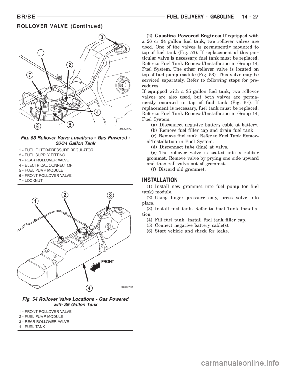
(2)Gasoline Powered Engines:If equipped with
a 26 or 34 gallon fuel tank, two rollover valves are
used. One of the valves is permanently mounted to
top of fuel tank (Fig. 53). If replacement of this par-
ticular valve is necessary, fuel tank must be replaced.
Refer to Fuel Tank Removal/Installation in Group 14,
Fuel System. The other rollover valve is located on
top of fuel pump module (Fig. 53). This valve may be
serviced separately. Refer to following steps for pro-
cedures.
If equipped with a 35 gallon fuel tank, two rollover
valves are also used, but both valves are perma-
nently mounted to top of fuel tank (Fig. 54). If
replacement is necessary, fuel tank must be replaced.
Refer to Fuel Tank Removal/Installation in Group 14,
Fuel System.
(a) Disconnect negative battery cable at battery.
(b) Remove fuel filler cap and drain fuel tank.
(c) Remove fuel tank. Refer to Fuel Tank Remov-
al/Installation in Fuel System.
(d) Disconnect tube (line) at valve.
(e) The rollover valve is seated into a rubber
grommet. Remove valve by prying one side upward
and then roll valve out of grommet.
(f) Discard old grommet.
INSTALLATION
(1) Install new grommet into fuel pump (or fuel
tank) module.
(2) Using finger pressure only, press valve into
place.
(3) Install fuel tank. Refer to Fuel Tank Installa-
tion.
(4) Fill fuel tank. Install fuel tank filler cap.
(5) Connect negative battery cable(s).
(6) Start vehicle and check for leaks.
Fig. 53 Rollover Valve Locations - Gas Powered -
26/34 Gallon Tank
1 - FUEL FILTER/PRESSURE REGULATOR
2 - FUEL SUPPLY FITTING
3 - REAR ROLLOVER VALVE
4 - ELECTRICAL CONNECTOR
5 - FUEL PUMP MODULE
6 - FRONT ROLLOVER VALVE
7 - LOCKNUT
Fig. 54 Rollover Valve Locations - Gas Powered
with 35 Gallon Tank
1 - FRONT ROLLOVER VALVE
2 - FUEL PUMP MODULE
3 - REAR ROLLOVER VALVE
4 - FUEL TANK
BR/BEFUEL DELIVERY - GASOLINE 14 - 27
ROLLOVER VALVE (Continued)
Page 1552 of 2889
CAUTION: Do not allow the ohmmeter to contact
terminals 85 or 86 during these tests. Damage to
ohmmeter may result.
(7) Attach the other jumper wire (12V +) to termi-
nal number 86. This will activate the relay. Continu-
ity should now be present between terminals number
87 and 30. Continuity should not be present between
terminals number 87A and 30.
(8) Disconnect jumper wires from relay and 12 Volt
power source.
(9) If continuity or resistance tests did not pass,
replace relay. If tests passed, refer to 8, Wiring Dia-
grams for (fuel system) relay wiring schematics and
for additional circuit information.
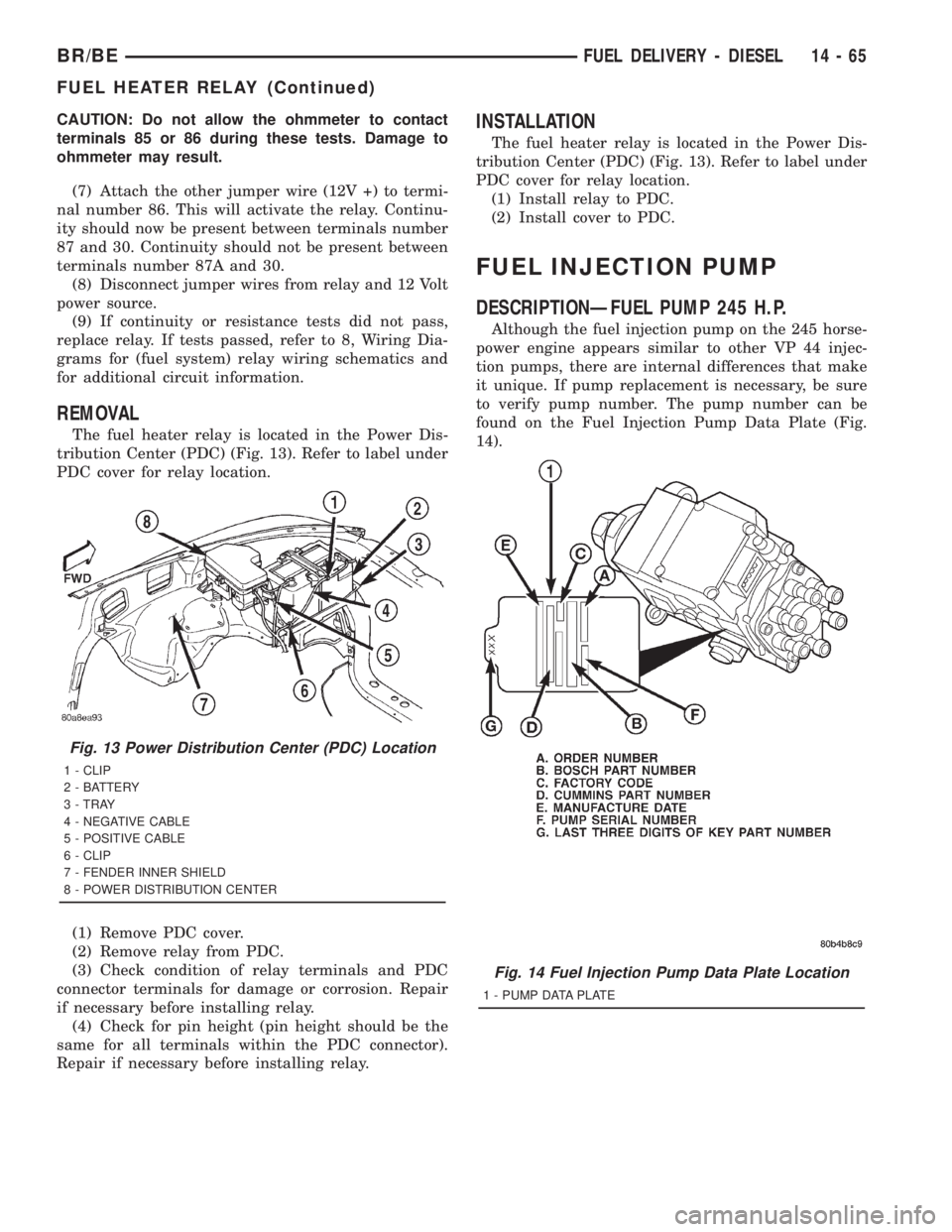
REMOVAL
The fuel heater relay is located in the Power Dis-
tribution Center (PDC) (Fig. 13). Refer to label under
PDC cover for relay location.
(1) Remove PDC cover.
(2) Remove relay from PDC.
(3) Check condition of relay terminals and PDC
connector terminals for damage or corrosion. Repair
if necessary before installing relay.
(4) Check for pin height (pin height should be the
same for all terminals within the PDC connector).
Repair if necessary before installing relay.
INSTALLATION
The fuel heater relay is located in the Power Dis-
tribution Center (PDC) (Fig. 13). Refer to label under
PDC cover for relay location.
(1) Install relay to PDC.
(2) Install cover to PDC.
FUEL INJECTION PUMP
DESCRIPTIONÐFUEL PUMP 245 H.P.
Although the fuel injection pump on the 245 horse-
power engine appears similar to other VP 44 injec-
tion pumps, there are internal differences that make
it unique. If pump replacement is necessary, be sure
to verify pump number. The pump number can be
found on the Fuel Injection Pump Data Plate (Fig.
14).
Fig. 13 Power Distribution Center (PDC) Location
1 - CLIP
2 - BATTERY
3 - TRAY
4 - NEGATIVE CABLE
5 - POSITIVE CABLE
6 - CLIP
7 - FENDER INNER SHIELD
8 - POWER DISTRIBUTION CENTER
Fig. 14 Fuel Injection Pump Data Plate Location
1 - PUMP DATA PLATE
BR/BEFUEL DELIVERY - DIESEL 14 - 65
FUEL HEATER RELAY (Continued)
Page 1562 of 2889
CAUTION: The high-pressure fuel lines must be
clamped securely in place in the holders. The lines
cannot contact each other or other components. Do
not attempt to weld high-pressure fuel lines or to
repair lines that are damaged. Only use the recom-
mended lines when replacement of high-pressure
fuel line is necessary.
REMOVAL
High-pressure lines are used between the fuel
injection pump and the fuel injectors only. All high-
pressure fuel lines are of the same length and inside
diameter. Correct high-pressure fuel line usage and
installation is critical to smooth engine operation.
CAUTION: Refer to Cleaning Fuel System Parts.
(1) Disconnect both negative battery cables from
both batteries. Cover and isolate ends of cables.
(2) Thoroughly clean fuel lines at cylinder head
and injection pump ends.
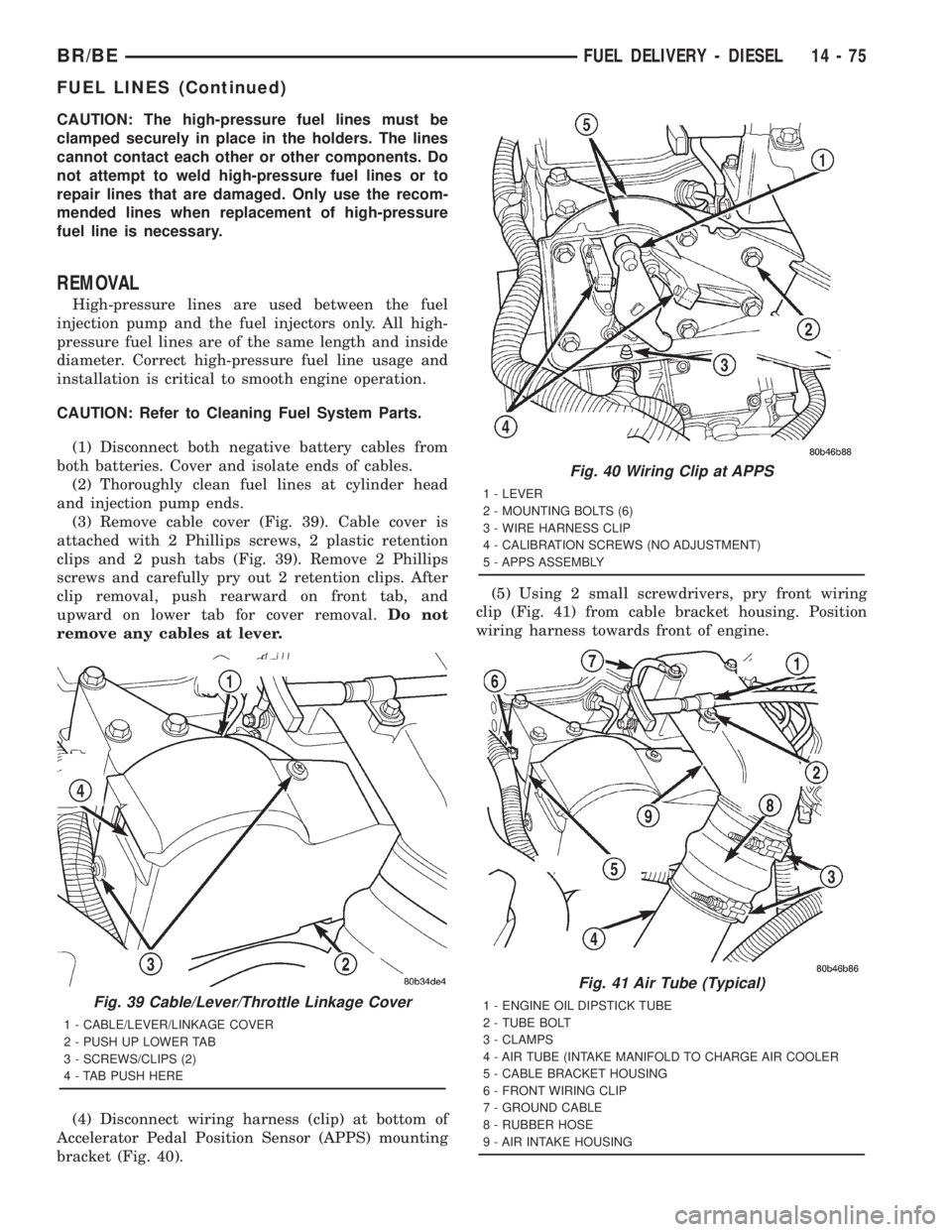
(3) Remove cable cover (Fig. 39). Cable cover is
attached with 2 Phillips screws, 2 plastic retention
clips and 2 push tabs (Fig. 39). Remove 2 Phillips
screws and carefully pry out 2 retention clips. After
clip removal, push rearward on front tab, and
upward on lower tab for cover removal.Do not
remove any cables at lever.
(4) Disconnect wiring harness (clip) at bottom of
Accelerator Pedal Position Sensor (APPS) mounting
bracket (Fig. 40).(5) Using 2 small screwdrivers, pry front wiring
clip (Fig. 41) from cable bracket housing. Position
wiring harness towards front of engine.
Fig. 39 Cable/Lever/Throttle Linkage Cover
1 - CABLE/LEVER/LINKAGE COVER
2 - PUSH UP LOWER TAB
3 - SCREWS/CLIPS (2)
4 - TAB PUSH HERE
Fig. 40 Wiring Clip at APPS
1 - LEVER
2 - MOUNTING BOLTS (6)
3 - WIRE HARNESS CLIP
4 - CALIBRATION SCREWS (NO ADJUSTMENT)
5 - APPS ASSEMBLY
Fig. 41 Air Tube (Typical)
1 - ENGINE OIL DIPSTICK TUBE
2 - TUBE BOLT
3 - CLAMPS
4 - AIR TUBE (INTAKE MANIFOLD TO CHARGE AIR COOLER
5 - CABLE BRACKET HOUSING
6 - FRONT WIRING CLIP
7 - GROUND CABLE
8 - RUBBER HOSE
9 - AIR INTAKE HOUSING
BR/BEFUEL DELIVERY - DIESEL 14 - 75
FUEL LINES (Continued)
Page 2574 of 2889
BODY
TABLE OF CONTENTS
page page
BODY
DESCRIPTION............................1
WARNING...............................1
DIAGNOSIS AND TESTING..................2
WATER LEAKS..........................2
WIND NOISE...........................3
SPECIFICATIONS.........................4
DECKLID/HATCH/LIFTGATE/TAILGATE........62
DOOR - FRONT..........................67DOOR - CARGO.........................77
EXTERIOR..............................86
HOOD.................................99
INSTRUMENT PANEL SYSTEM.............104
INTERIOR.............................118
PAINT................................129
SEATS................................131
STATIONARY GLASS.....................145
WEATHERSTRIP/SEALS..................152
BODY
DESCRIPTION ± PUSH-IN FASTENERS
DaimlerChrysler Corporation uses many different
types of push-in fasteners to secure the interior and
exterior trim to the body. Most of these fasteners can
be reused to assemble the trim during various repair
procedures. At times, a push-in fastener cannot be
removed without damaging the fastener or the com-
ponent it is holding. If it is not possible to remove a
fastener without damaging a component or body, cut
or break the fastener and use a new one when
installing the component. Never pry or pound on a
plastic or pressed-board trim component. Using a
suitable fork-type prying device, pry the fastener
from the retaining hole behind the component being
removed. When installing, verify fastener alignment
with the retaining hole by hand. Push directly on or
over the fastener until it seats. Apply a low-force pull
to the panel to verify that it is secure.
When it is necessary to remove components to ser-
vice another, it should not be necessary to apply
excessive force or bend a component to remove it.
Before damaging a trim component, verify hidden
fasteners or captured edges holding the component in
place.
DESCRIPTION ± LOCK CYLINDERS
Ignition, door, deck lid, and rear hatch lock cylin-
ders are all codable to the key. Lock barrels, tum-
blers, and tumbler springs are available to allow the
technician to change replacement locks cylinders to
match the customer's original key set. See the appro-
priate section in this manual for lock cylinder
removal. See the Moparž catalogue for part numbers
and lock coding procedures.
SAFETY PRECAUTIONS AND WARNINGS
WARNING: USE A OSHA APPROVED BREATHING
FILTER WHEN SPRAYING PAINT OR SOLVENTS IN
A CONFINED AREA. PERSONAL INJURY CAN
RESULT.
AVOID PROLONGED SKIN CONTACT WITH PETRO-
LEUM OR ALCOHOL ± BASED CLEANING SOL-
VENTS. PERSONAL INJURY CAN RESULT.
DO NOT STAND UNDER A HOISTED VEHICLE THAT
IS NOT PROPERLY SUPPORTED ON SAFETY
STANDS. PERSONAL INJURY CAN RESULT.
CAUTION: When holes must be drilled or punched
in an inner body panel, verify depth of space to the
outer body panel, electrical wiring, or other compo-
nents. Damage to vehicle can result.
Do not weld exterior panels unless combustible
material on the interior of vehicle is removed from
the repair area. Fire or hazardous conditions, can
result.
Always have a fire extinguisher ready for use when
welding.
Disconnect the negative (-) cable clamp from the
battery when servicing electrical components that
are live when the ignition is OFF. Damage to electri-
cal system can result.
Do not use abrasive chemicals or compounds on
painted surfaces. Damage to finish can result.
Do not use harsh alkaline based cleaning solvents
on painted or upholstered surfaces. Damage to fin-
ish or color can result.
Do not hammer or pound on plastic trim panel
when servicing interior trim. Plastic panels can
break.
BR/BEBODY 23 - 1
Page 2736 of 2889
Heater Diagnosis
CONDITION POSSIBLE CAUSE CORRECTION
INSUFFICIENT HEATER
OUTPUT.1. Incorrect engine
coolant level.1. Check the engine coolant level. Refer to Cooling for
the procedures.
2. Air trapped in engine
cooling system.2. Check the operation of the coolant reserve/recovery
system. Refer to Cooling for the procedures.
3. Incorrect engine
coolant temperature.3. Check the performance and operation of the engine
cooling system including: thermostat, water pump, fan
drive, accessory drive belt, coolant flow (plugged radiator
or heater core, plugged or kinked coolant hoses), air flow
(missing or improperly installed radiator air seals or fan
shroud). Refer to Cooling for the procedures.
4. Blend door actuator
inoperative or defective.4. (Refer to Controls/Blend Door Actuator) in this group.
5. Blend door not
operating properly.5. Check for a damaged, obstructed or improperly
installed blend door or seals. (Refer to Controls/Blend
Door Actuator) in this group.
6. Insufficient air flow
through heater housing.6. Remove foreign material or obstructions from cowl air
intake.
7. Improper blower motor
operation.7. (Refer to Distribution/Blower Motor/ Diagnosis and
Testing) in this group.
STANDARD PROCEDURE - DIODE
REPLACEMENT
(1) Disconnect the battery.
(2) Locate the diode in the harness, and remove
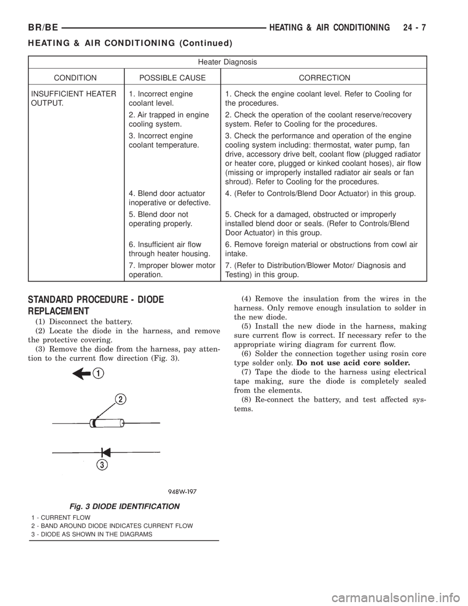
the protective covering.
(3) Remove the diode from the harness, pay atten-
tion to the current flow direction (Fig. 3).(4) Remove the insulation from the wires in the
harness. Only remove enough insulation to solder in
the new diode.
(5) Install the new diode in the harness, making
sure current flow is correct. If necessary refer to the
appropriate wiring diagram for current flow.
(6) Solder the connection together using rosin core
type solder only.Do not use acid core solder.
(7) Tape the diode to the harness using electrical
tape making, sure the diode is completely sealed
from the elements.
(8) Re-connect the battery, and test affected sys-
tems.
Fig. 3 DIODE IDENTIFICATION
1 - CURRENT FLOW
2 - BAND AROUND DIODE INDICATES CURRENT FLOW
3 - DIODE AS SHOWN IN THE DIAGRAMS
BR/BEHEATING & AIR CONDITIONING 24 - 7
HEATING & AIR CONDITIONING (Continued)