2001 DODGE RAM battery replacement
[x] Cancel search: battery replacementPage 419 of 2889
erally used to clean automatic transmission compo-
nents.DO NOTuse solvents containing acids, water,
gasoline, or any other corrosive liquids.
(2) Reinstall filler plug on Tool 6906B.
(3) Verify pump power switch is turned OFF. Con-
nect red alligator clip to positive (+) battery post.
Connect black (-) alligator clip to a good ground.
(4) Disconnect the cooler lines at the transmission.
NOTE: When flushing transmission cooler and
lines, ALWAYS reverse flush.
NOTE: The converter drainback valve must be
removed and an appropriate replacement hose
installed to bridge the space between the transmis-
sion cooler line and the cooler fitting. Failure to
remove the drainback valve will prevent reverse
flushing the system. A suitable replacement hose
can be found in the adapter kit supplied with the
flushing tool.
(5) Connect the BLUE pressure line to the OUT-
LET (From) cooler line.
(6) Connect the CLEAR return line to the INLET
(To) cooler line
(7) Remove the transmission oil cooler from the
vehicle. (Refer to 7 - COOLING/TRANSMISSION/
TRANS COOLER - REMOVAL)
(8) Remove the transmission oil cooler thermostat.
(Refer to 7 - COOLING/TRANSMISSION/TRANS
COOLER - DISASSEMBLY)
(9) Re-install the thermostat cover onto the oil
cooler and install the snap-ring.
(10) Re-connect the oil cooler to the transmission
cooler lines.
(11) Turn pump ON for two to three minutes to
flush cooler(s) and lines.
NOTE: This flushes the bypass circuit of the cooler
only.
(12) Turn pump OFF.
(13) Remove the thermostat cover from the oil
cooler.
(14) Install Special Tool Cooler Plug 8414 into the
transmission oil cooler.
(15) Re-install the thermostat cover onto the oil
cooler and install the snap-ring.
(16) Turn pump ON for two to three minutes to
flush cooler(s) and lines.
NOTE: This flushes the main oil cooler core pas-
sages only.
(17) Turn pump OFF.
(18) Remove the thermostat cover from the oil
cooler.(19) Remove Special Tool Cooler Plug 8414 from
the transmission oil cooler.
(20) Install a new thermostat spring, thermostat,
cover, and snap-ring into the transmission oil cooler.
(Refer to 7 - COOLING/TRANSMISSION/TRANS
COOLER - ASSEMBLY)
(21) Install the transmission oil cooler onto the
vehicle. (Refer to 7 - COOLING/TRANSMISSION/
TRANS COOLER - INSTALLATION)
(22) Disconnect CLEAR suction line from reservoir
at cover plate. Disconnect CLEAR return line at
cover plate, and place it in a drain pan.
(23) Turn pump ON for 30 seconds to purge flush-
ing solution from cooler and lines. Turn pump OFF.
(24) Place CLEAR suction line into a one quart
container of MopartATF +4, type 9602, Automatic
Transmission fluid.
(25) Turn pump ON until all transmission fluid is
removed from the one quart container and lines. This
purges any residual cleaning solvent from the trans-
mission cooler and lines. Turn pump OFF.
(26) Disconnect alligator clips from battery. Recon-
nect flusher lines to cover plate, and remove flushing
adapters from cooler lines.
REMOVAL
(1) Place a drain pan under the oil cooler lines.
(2) Disconnect the two transmission lines from the
oil cooler by loosening the two worm gear clamps and
pulling the rubber hoses off of the oil cooler tubes
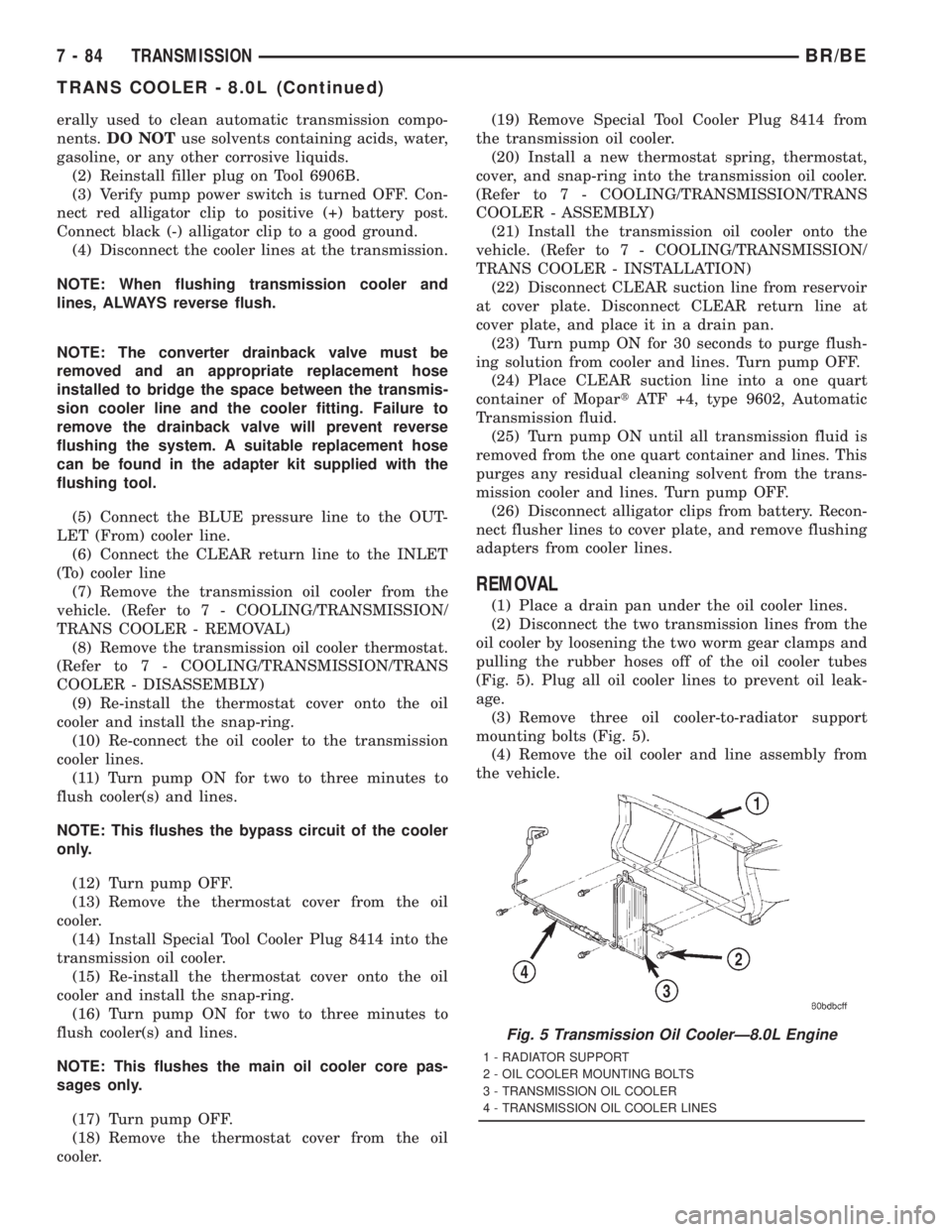
(Fig. 5). Plug all oil cooler lines to prevent oil leak-
age.
(3) Remove three oil cooler-to-radiator support
mounting bolts (Fig. 5).
(4) Remove the oil cooler and line assembly from
the vehicle.
Fig. 5 Transmission Oil CoolerÐ8.0L Engine
1 - RADIATOR SUPPORT
2 - OIL COOLER MOUNTING BOLTS
3 - TRANSMISSION OIL COOLER
4 - TRANSMISSION OIL COOLER LINES
7 - 84 TRANSMISSIONBR/BE
TRANS COOLER - 8.0L (Continued)
Page 421 of 2889
WARNING: WEAR PROTECTIVE EYEWEAR THAT
MEETS THE REQUIREMENTS OF OSHA AND ANSI
Z87.1±1968. WEAR STANDARD INDUSTRIAL RUB-
BER GLOVES.
KEEP LIGHTED CIGARETTES, SPARKS, FLAMES,
AND OTHER IGNITION SOURCES AWAY FROM THE
AREA TO PREVENT THE IGNITION OF COMBUSTI-
BLE LIQUIDS AND GASES. KEEP A CLASS (B) FIRE
EXTINGUISHER IN THE AREA WHERE THE
FLUSHER WILL BE USED.
KEEP THE AREA WELL VENTILATED.
DO NOT LET FLUSHING SOLVENT COME IN CON-
TACT WITH YOUR EYES OR SKIN: IF EYE CONTAM-
INATION OCCURS, FLUSH EYES WITH WATER FOR
15 TO 20 SECONDS. REMOVE CONTAMINATED
CLOTHING AND WASH AFFECTED SKIN WITH
SOAP AND WATER. SEEK MEDICAL ATTENTION.
(1) Remove cover plate filler plug on Tool 6906-B.
Fill reservoir 1/2 to 3/4 full of fresh flushing solution.
Flushing solvents are petroleum based solutions gen-
erally used to clean automatic transmission compo-
nents.DO NOTuse solvents containing acids, water,
gasoline, or any other corrosive liquids.
(2) Reinstall filler plug on Tool 6906-B.
(3) Verify pump power switch is turned OFF. Con-
nect red alligator clip to positive (+) battery post.
Connect black (-) alligator clip to a good ground.
(4) Disconnect the cooler lines at the transmission.
NOTE: When flushing transmission cooler and
lines, ALWAYS reverse flush.
NOTE: The converter drainback valve must be
removed and an appropriate replacement hose
installed to bridge the space between the transmis-
sion cooler line and the cooler fitting. Failure to
remove the drainback valve will prevent reverse
flushing the system. A suitable replacement hose
can be found in the adapter kit supplied with the
flushing tool.
(5) Connect the BLUE pressure line to the OUT-
LET (From) cooler line.
(6) Connect the CLEAR return line to the INLET
(To) cooler line
(7) Turn pump ON for two to three minutes to
flush cooler(s) and lines.
(8) Turn pump OFF.
(9) Disconnect CLEAR suction line from reservoir
at cover plate. Disconnect CLEAR return line at
cover plate, and place it in a drain pan.
(10) Turn pump ON for 30 seconds to purge flush-
ing solution from cooler and lines. Turn pump OFF.(11) Place CLEAR suction line into a one quart
container of MopartATF +4, type 9602, Automatic
Transmission Fluid.
(12) Turn pump ON until all transmission fluid is
removed from the one quart container and lines. This
purges any residual cleaning solvent from the trans-
mission cooler and lines. Turn pump OFF.
(13) Disconnect alligator clips from battery. Recon-
nect flusher lines to cover plate, and remove flushing
adapters from cooler lines.
STANDARD PROCEDURE - FLUSHING COOLER
AND TUBES - WITHOUT RADIATOR IN-TANK
TRANSMISSION OIL COOLER
When a transmission failure has contaminated the
fluid, the oil cooler(s) must be flushed. The torque
converter must also be replaced. This will insure that
metal particles or sludged oil are not later trans-
ferred back into the reconditioned (or replaced) trans-
mission.
(1) Remove cover plate filler plug on Tool 6906B.
Fill reservoir 1/2 to 3/4 full of fresh flushing solution.
Flushing solvents are petroleum based solutions gen-
erally used to clean automatic transmission compo-
nents.DO NOTuse solvents containing acids, water,
gasoline, or any other corrosive liquids.
(2) Reinstall filler plug on Tool 6906B.
(3) Verify pump power switch is turned OFF. Con-
nect red alligator clip to positive (+) battery post.
Connect black (-) alligator clip to a good ground.
(4) Disconnect the cooler lines at the transmission.
NOTE: When flushing transmission cooler and
lines, ALWAYS reverse flush.
NOTE: The converter drainback valve must be
removed and an appropriate replacement hose
installed to bridge the space between the transmis-
sion cooler line and the cooler fitting. Failure to
remove the drainback valve will prevent reverse
flushing the system. A suitable replacement hose
can be found in the adapter kit supplied with the
flushing tool.
(5) Connect the BLUE pressure line to the OUT-
LET (From) cooler line.
(6) Connect the CLEAR return line to the INLET
(To) cooler line
(7) Remove the transmission oil cooler from the
vehicle. (Refer to 7 - COOLING/TRANSMISSION/
TRANS COOLER - REMOVAL)
(8) Remove the transmission oil cooler thermostat.
(Refer to 7 - COOLING/TRANSMISSION/TRANS
COOLER - DISASSEMBLY)
7 - 86 TRANSMISSIONBR/BE
TRANS COOLER - 5.9L DIESEL (Continued)
Page 431 of 2889
securely to the connector on the end of the antenna
cable being installed into the instrument panel. This
cord will be used to pull or ªfishº the cable back into
position.
(2) Using the cord or twine, pull the antenna cable
through the radio receiver opening from under the
instrument panel.
(3) Install the radio receiver onto the instrument
panel.
(4) Reach through the glove box opening to engage
the antenna cable with the retainer clips on the back
of the instrument panel.
(5) Install the glove box onto the instrument panel.
(6) Untie the cord or twine from the instrument
panel antenna cable connector.
(7) Reach under the passenger side of the instru-
ment panel near the right cowl side inner panel to
reconnect the two halves of the radio antenna coaxial
cable connector. Wrap the connection with a piece of
foam tape.
(8) Engage the coaxial cable connector with the
retainer clip located on the bottom of the heater-A/C
housing.
(9) Reconnect the battery negative cable.
RADIO CHOKE RELAY
DESCRIPTION
Models equipped with the Infinity premium
speaker package have a filter, choke, and speaker
relay unit. The filter, choke, and speaker relay unit is
mounted to the lower instrument panel center brace,
inboard of the Central Timer Module (CTM) and
directly above the 16-way data link connector. The
filter, choke, and speaker relay unit can be accessed
for service without instrument panel disassembly or
removal.
The filter, choke, and speaker relay unit should be
checked if there is no sound output noted from the
speakers. The filter, choke, and speaker relay unit
cannot be repaired or adjusted and, if faulty or dam-
aged, the unit must be replaced.
OPERATION
The filter, choke, and speaker relay unit is used to
control the supply of fused battery current to the
front door speaker-mounted dual amplifiers. The
speaker relay is energized by a fused 12 volt output
from the radio receiver whenever the radio is turned
on. For complete circuit diagrams, refer to the appro-
priate wiring information. The wiring information
includes wiring diagrams, proper wire and connector
repair procedures, details of wire harness routing
and retention, connector pin-out information andlocation views for the various wire harness connec-
tors, splices and grounds.
DIAGNOSIS AND TESTING - RADIO CHOKE
RELAY
The filter, choke and speaker relay is used to
switch power to the individual speaker amplifiers
used with the Infinity premium speaker package.
The choke and relay are serviced only as a unit. If all
of the speakers are inoperative the filter, choke and
speaker relay unit should be considered suspect.
However, before replacement make the following
checks of the filter, choke and speaker relay circuits.
For complete circuit diagrams, refer to the appropri-
ate wiring information. The wiring information
includes wiring diagrams, proper wire and connector
repair procedures, details of wire harness routing
and retention, connector pin-out information and
location views for the various wire harness connec-
tors, splices and grounds.
(1)
Check the fused B(+) fuse in the junction block.
If OK, go to Step 2. If not OK, replace the faulty fuse.
(2) Check for battery voltage at the fused B(+) fuse
in the junction block. If OK, go to Step 3. If not OK,
repair the open fused B(+) circuit to the battery as
required.
(3) Disconnect the instrument panel wire harness
connector from the filter, choke and speaker relay
unit. Check for battery voltage at the fused B(+) cir-
cuit cavity of the instrument panel wire harness con-
nector for the filter, choke and speaker relay unit. If
OK, go to Step 4. If not OK, repair the open fused
B(+) circuit to the junction block fuse as required.
(4) Probe the ground circuit cavity of the instru-
ment panel wire harness connector for the filter,
choke and speaker relay unit. Check for continuity to
a good ground. There should be continuity. If OK, go
to Step 5. If not OK, repair the open ground circuit to
ground as required.
(5) Turn the ignition switch to the On position and
turn the radio on. Check for battery voltage at the
radio 12-volt output circuit cavity of the instrument
panel wire harness connector for the filter, choke and
speaker relay unit. If OK, go to Step 6. If not OK,
repair the open radio 12-volt output circuit to the
radio as required.
(6) Turn the radio and ignition switches to the Off
position. Reconnect the instrument panel wire har-
ness connector to the filter, choke and speaker relay
unit. Check for battery voltage at the amplified
speaker (+) circuit cavity of the instrument panel
wire harness connector for the filter, choke and
speaker relay unit. There should be zero volts. Turn
the ignition and radio switches to the On position.
8A - 8 AUDIOBR/BE
ANTENNA BODY & CABLE (Continued)
Page 436 of 2889
²Wiper motor.
If the source of RFI or EMI noise is identified as a
component on the vehicle (i.e., generator, blower
motor, etc.), the ground path for that component
should be checked. If excessive resistance is found in
any ground circuit, clean, tighten, or repair the
ground circuits or connections to ground as required
before considering any component replacement.
For service and inspection of secondary ignition
components, refer to Electrical, Ignition Control.
Inspect the following secondary ignition system com-
ponents:
²Distributor cap and rotor
²Ignition coil
²Spark plugs
²Spark plug wire routing and condition.
Reroute the spark plug wires or replace the faulty
components as required.
If the source of the RFI or EMI noise is identified
as two-way mobile radio or telephone equipment,
check the equipment installation for the following:
²Power connections should be made directly to
the battery, and fused as closely to the battery as
possible.
²The antenna should be mounted on the roof or
toward the rear of the vehicle. Remember that mag-
netic antenna mounts on the roof panel can adversely
affect the operation of an overhead console compass,
if the vehicle is so equipped.
²The antenna cable should be fully shielded coax-
ial cable, should be as short as is practical, and
should be routed away from the factory-installed
vehicle wire harnesses whenever possible.
²The antenna and cable must be carefully
matched to ensure a low Standing Wave Ratio
(SWR).
Fleet vehicles are available with an extra-cost RFI-
suppressed Powertrain Control Module (PCM). This
unit reduces interference generated by the PCM on
some radio frequencies used in two-way radio com-
munications. However, this unit will not resolve com-
plaints of RFI in the commercial AM or FM radio
frequency ranges.
ENGINE-TO-BODY GROUND
STRAP
REMOVAL
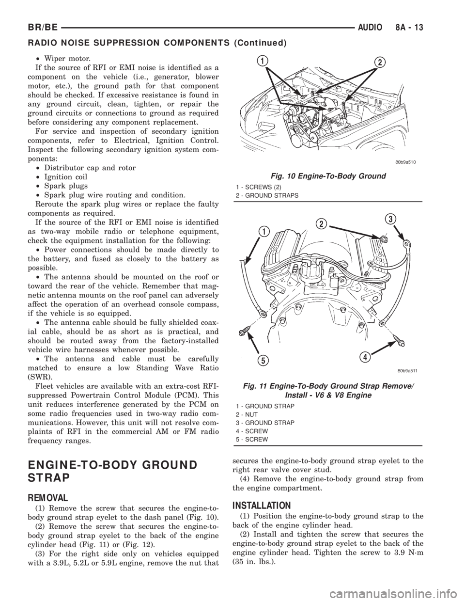
(1) Remove the screw that secures the engine-to-
body ground strap eyelet to the dash panel (Fig. 10).
(2) Remove the screw that secures the engine-to-
body ground strap eyelet to the back of the engine
cylinder head (Fig. 11) or (Fig. 12).
(3) For the right side only on vehicles equipped
with a 3.9L, 5.2L or 5.9L engine, remove the nut thatsecures the engine-to-body ground strap eyelet to the
right rear valve cover stud.
(4) Remove the engine-to-body ground strap from
the engine compartment.INSTALLATION
(1) Position the engine-to-body ground strap to the
back of the engine cylinder head.
(2) Install and tighten the screw that secures the
engine-to-body ground strap eyelet to the back of the
engine cylinder head. Tighten the screw to 3.9 N´m
(35 in. lbs.).
Fig. 10 Engine-To-Body Ground
1 - SCREWS (2)
2 - GROUND STRAPS
Fig. 11 Engine-To-Body Ground Strap Remove/
Install - V6 & V8 Engine
1 - GROUND STRAP
2 - NUT
3 - GROUND STRAP
4 - SCREW
5 - SCREW
BR/BEAUDIO 8A - 13
RADIO NOISE SUPPRESSION COMPONENTS (Continued)
Page 456 of 2889
CTM from the CTM connector receptacle(s). Check
the wire harness connectors and the CTM receptacles
for loose, corroded, or damaged terminals and pins. If
OK, go to Step 6. If not OK, repair as required.
(6) Check for continuity between the ground cir-
cuit cavity of the instrument panel wire harness con-
nector (Connector C1) for the CTM and a good
ground. For the high-line/premium version of the
CTM only, repeat the check between the ground cir-
cuit cavity of the instrument panel wire harness con-
nector (Connector C2) for the CTM and a good
ground. In each case, there should be continuity. If
OK, go to Step 7. If not OK, repair the open ground
circuit(s) to ground as required.
(7) Reconnect the battery negative cable. Check for
battery voltage at the fused B(+) circuit cavity of the
instrument panel wire harness connector (Connector
C1) for the CTM. If OK, go to Step 8. If not OK,
repair the open fused B(+) circuit between the CTM
and the JB as required.
(8) Turn the ignition switch to the On position.
Check for battery voltage at the fused ignition switch
output (st-run) circuit cavity (base version) or fused
ignition switch output (run-acc) circuit cavity (high-
line/premium version) of the instrument panel wire
harness connector (Connector C1) for the CTM. If OK
with a base version CTM, replace the faulty CTM. If
OK with a high-line/premium version CTM, use a
DRBIIItscan tool and the appropriate diagnostic
information to perform further diagnosis of the CTM.
If not OK, repair the open fused ignition switch out-
put circuit between the CTM and the JB.
REMOVAL
WARNING: ON VEHICLES EQUIPPED WITH AIR-
BAGS, DISABLE THE AIRBAG SYSTEM BEFORE
ATTEMPTING ANY STEERING WHEEL, STEERING
COLUMN, OR INSTRUMENT PANEL COMPONENT
DIAGNOSIS OR SERVICE. DISCONNECT AND ISO-
LATE THE BATTERY NEGATIVE (GROUND) CABLE,
THEN WAIT TWO MINUTES FOR THE AIRBAG SYS-
TEM CAPACITOR TO DISCHARGE BEFORE PER-
FORMING FURTHER DIAGNOSIS OR SERVICE. THIS
IS THE ONLY SURE WAY TO DISABLE THE AIRBAG
SYSTEM. FAILURE TO TAKE THE PROPER PRE-
CAUTIONS COULD RESULT IN ACCIDENTAL AIR-
BAG DEPLOYMENT AND POSSIBLE PERSONAL
INJURY.
NOTE: Before replacing a high-line/premium version
Central Timer Module (CTM), use a DRBIIITscan
tool to retrieve the current settings for the CTM pro-
grammable features. Refer to the appropriate diag-
nostic information. These settings should be
duplicated in the replacement high-line/premiumCTM using the DRBIIITscan tool before returning
the vehicle to service.
(1) Disconnect and isolate the battery negative
cable.
(2) Remove the steering column opening cover
from the instrument panel. (Refer to 23 - BODY/IN-
STRUMENT PANEL/STEERING COLUMN OPEN-
ING COVER - REMOVAL).
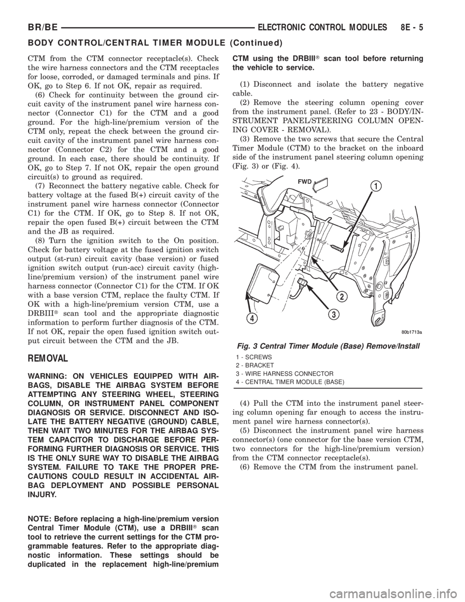
(3) Remove the two screws that secure the Central
Timer Module (CTM) to the bracket on the inboard
side of the instrument panel steering column opening
(Fig. 3) or (Fig. 4).
(4) Pull the CTM into the instrument panel steer-
ing column opening far enough to access the instru-
ment panel wire harness connector(s).
(5) Disconnect the instrument panel wire harness
connector(s) (one connector for the base version CTM,
two connectors for the high-line/premium version)
from the CTM connector receptacle(s).
(6) Remove the CTM from the instrument panel.
Fig. 3 Central Timer Module (Base) Remove/Install
1 - SCREWS
2 - BRACKET
3 - WIRE HARNESS CONNECTOR
4 - CENTRAL TIMER MODULE (BASE)
BR/BEELECTRONIC CONTROL MODULES 8E - 5
BODY CONTROL/CENTRAL TIMER MODULE (Continued)
Page 457 of 2889

INSTALLATION
WARNING: ON VEHICLES EQUIPPED WITH AIR-
BAGS, DISABLE THE AIRBAG SYSTEM BEFORE
ATTEMPTING ANY STEERING WHEEL, STEERING
COLUMN, OR INSTRUMENT PANEL COMPONENT
DIAGNOSIS OR SERVICE. DISCONNECT AND ISO-
LATE THE BATTERY NEGATIVE (GROUND) CABLE,
THEN WAIT TWO MINUTES FOR THE AIRBAG SYS-
TEM CAPACITOR TO DISCHARGE BEFORE PER-
FORMING FURTHER DIAGNOSIS OR SERVICE. THIS
IS THE ONLY SURE WAY TO DISABLE THE AIRBAG
SYSTEM. FAILURE TO TAKE THE PROPER PRE-
CAUTIONS COULD RESULT IN ACCIDENTAL AIR-
BAG DEPLOYMENT AND POSSIBLE PERSONAL
INJURY.
NOTE: Before replacing a high-line/premium version
Central Timer Module (CTM), use a DRBIIITscan
tool to retrieve the current settings for the CTM pro-
grammable features. Refer to the appropriate diag-
nostic information. These settings should be
duplicated in the replacement high-line/premium
CTM using the DRBIIITscan tool before returning
the vehicle to service.(1) Position the CTM to the inboard side of the
instrument panel steering column opening.
(2) Reconnect the instrument panel wire harness
connector(s) for the CTM (one connector for the base
version CTM, two connectors for the high-line/pre-
mium version) to the CTM connector receptacle(s)
(Fig. 3) or (Fig. 4).
(3) Position the CTM to the bracket on the inboard
side of the instrument panel steering column open-
ing.
(4) Install and tighten the two screws that secure
the CTM to the bracket on the inboard side of instru-
ment panel steering column opening. Tighten the
screws to 1.6 N´m (15 in. lbs.).
(5) Reinstall the steering column opening cover
onto the instrument panel. (Refer to 23 - BODY/IN-
STRUMENT PANEL/STEERING COLUMN OPEN-
ING COVER - INSTALLATION).
(6) Reconnect the battery negative cable.
COMMUNICATION
DESCRIPTION - CCD DATA BUS
The Chrysler Collision Detection (also referred to
as CCD or C2D ) data bus system is a multiplex sys-
tem used for vehicle communications on many
Chrysler Corporation vehicles. Within the context of
the CCD system, the term ªcollisionª refers to the
system's ability to avoid collisions of the electronic
data that enters the data bus from various electronic
control modules at approximately the same time.
Multiplexing is a system that enables the trans-
mission of several messages over a single channel or
circuit. Many Chrysler vehicles use this principle for
communication between the various microprocessor-
based electronic control modules.
Many of the electronic control modules in a vehicle
require information from the same sensing device. In
the past, if information from one sensing device was
required by several controllers, a wire from each con-
troller needed to be connected in parallel to that sen-
sor. In addition, each controller utilizing analog
sensors required an Analog/Digital (A/D) converter in
order to ªreadª these sensor inputs. Multiplexing
reduces wire harness complexity, sensor current
loads and controller hardware because each sensing
device is connected to only one controller, which
reads and distributes the sensor information to the
other controllers over the data bus. Also, because
each controller on the data bus can access the con-
troller sensor inputs to every other controller on the
data bus, more function and feature capabilities are
possible.
Fig. 4 Central Timer Module (High-Line/Premium)
Remove/Install
1 - SCREWS
2 - BRACKET
3 - WIRE HARNESS CONNECTORS
4 - CENTRAL TIMER MODULE (HIGH-LINE/PREMIUM)
8E - 6 ELECTRONIC CONTROL MODULESBR/BE
BODY CONTROL/CENTRAL TIMER MODULE (Continued)
Page 476 of 2889
²A faulty or incorrect starting system component.
Refer to Starting System for the proper starting sys-
tem diagnosis and testing procedures.
²A faulty or incorrect battery. Refer to Standard
Procedures for the proper battery diagnosis and test-
ing procedures. Refer to Battery System Specifica-
tions for the proper specifications.
CLEANING
The following information details the recommended
cleaning procedures for the battery and related com-
ponents. In addition to the maintenance schedules
found in this service manual and the owner's man-
ual, it is recommended that these procedures be per-
formed any time the battery or related components
must be removed for vehicle service.
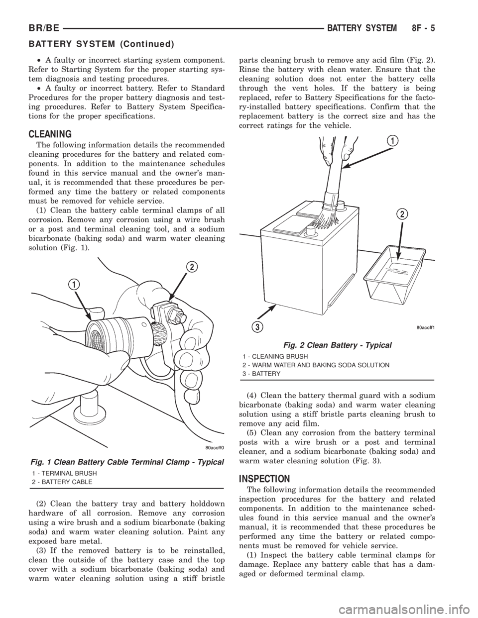
(1) Clean the battery cable terminal clamps of all
corrosion. Remove any corrosion using a wire brush
or a post and terminal cleaning tool, and a sodium
bicarbonate (baking soda) and warm water cleaning
solution (Fig. 1).
(2) Clean the battery tray and battery holddown
hardware of all corrosion. Remove any corrosion
using a wire brush and a sodium bicarbonate (baking
soda) and warm water cleaning solution. Paint any
exposed bare metal.
(3) If the removed battery is to be reinstalled,
clean the outside of the battery case and the top
cover with a sodium bicarbonate (baking soda) and
warm water cleaning solution using a stiff bristleparts cleaning brush to remove any acid film (Fig. 2).
Rinse the battery with clean water. Ensure that the
cleaning solution does not enter the battery cells
through the vent holes. If the battery is being
replaced, refer to Battery Specifications for the facto-
ry-installed battery specifications. Confirm that the
replacement battery is the correct size and has the
correct ratings for the vehicle.
(4) Clean the battery thermal guard with a sodium
bicarbonate (baking soda) and warm water cleaning
solution using a stiff bristle parts cleaning brush to
remove any acid film.
(5) Clean any corrosion from the battery terminal
posts with a wire brush or a post and terminal
cleaner, and a sodium bicarbonate (baking soda) and
warm water cleaning solution (Fig. 3).
INSPECTION
The following information details the recommended
inspection procedures for the battery and related
components. In addition to the maintenance sched-
ules found in this service manual and the owner's
manual, it is recommended that these procedures be
performed any time the battery or related compo-
nents must be removed for vehicle service.
(1) Inspect the battery cable terminal clamps for
damage. Replace any battery cable that has a dam-
aged or deformed terminal clamp.
Fig. 1 Clean Battery Cable Terminal Clamp - Typical
1 - TERMINAL BRUSH
2 - BATTERY CABLE
Fig. 2 Clean Battery - Typical
1 - CLEANING BRUSH
2 - WARM WATER AND BAKING SODA SOLUTION
3 - BATTERY
BR/BEBATTERY SYSTEM 8F - 5
BATTERY SYSTEM (Continued)
Page 489 of 2889
(4) Clean the battery cable terminal clamps and
the battery terminal posts. Refer toBattery System
in this group for the location of the proper battery
system cleaning and inspection procedures.
(5) Reconnect the battery positive cable terminal
clamp to the battery positive terminal post. Tighten
the terminal clamp pinch-bolt hex nut to 4 N´m (35
in. lbs.).
(6) Reconnect the battery negative cable terminal
clamp to the battery negative terminal post. Tighten
the terminal clamp pinch-bolt hex nut to 4 N´m (35
in. lbs.).
(7) Apply a thin coating of petroleum jelly or chas-
sis grease to the exposed surfaces of the battery cable
terminal clamps and the battery terminal posts.
BATTERY HOLDDOWN
DESCRIPTION
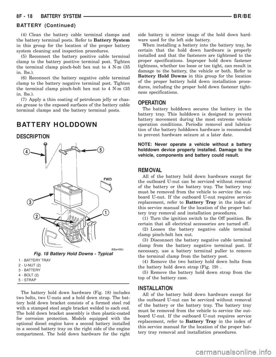
The battery hold down hardware (Fig. 18) includes
two bolts, two U-nuts and a hold down strap. The bat-
tery hold down bracket consists of a formed steel rod
with a stamped steel angle bracket welded to each end.
The hold down bracket assembly is then plastic-coated
for corrosion protection. Models equipped with the
optional diesel engine have a second battery installed
in a second battery tray on the right side of the engine
compartment. The hold down hardware for the rightside battery is mirror image of the hold down hard-
ware used for the left side battery.
When installing a battery into the battery tray, be
certain that the hold down hardware is properly
installed and that the fasteners are tightened to the
proper specifications. Improper hold down fastener
tightness, whether too loose or too tight, can result in
damage to the battery, the vehicle or both. Refer to
Battery Hold Downsin this group for the location
of the proper battery hold down installation proce-
dures, including the proper hold down fastener tight-
ness specifications.
OPERATION
The battery holddown secures the battery in the
battery tray. This holddown is designed to prevent
battery movement during the most extreme vehicle
operation conditions. Periodic removel and lubrica-
tion of the battery holddown hardware is recomended
to prevent hardware seizure at a later date.
NOTE: Never operate a vehicle without a battery
holddown device properly installed. Damage to the
vehicle, components and battery could result.
REMOVAL
All of the battery hold down hardware except for
the outboard U-nut can be serviced without removal
of the battery or the battery tray. The battery tray
must be removed from the vehicle to service the out-
board U-nut. If the outboard U-nut requires service
replacement, refer toBattery Trayin the index of
this service manual for the location of the proper bat-
tery tray removal and installation procedures.
(1) Turn the ignition switch to the Off position. Be
certain that all electrical accessories are turned off.
(2) Loosen the battery negative cable terminal
clamp pinch-bolt hex nut.
(3) Disconnect the battery negative cable terminal
clamp from the battery negative terminal post. If
necessary, use a battery terminal puller to remove
the terminal clamp from the battery post.
(4) Remove the two battery hold down bolts from
the battery hold down strap (Fig. 19) .
(5) Remove the battery hold down strap from the
top of the battery case.
INSTALLATION
All of the battery hold down hardware except for
the outboard U-nut can be serviced without removal
of the battery or the battery tray. The battery tray
must be removed from the vehicle to service the out-
board U-nut. If the outboard U-nut requires service
replacement, refer toBattery Trayin the index of
this service manual for the location of the proper bat-
tery tray removal and installation procedures.
Fig. 18 Battery Hold Downs - Typical
1 - BATTERY TRAY
2 - U-NUT (2)
3 - BATTERY
4 - BOLT (2)
5 - STRAP
8F - 18 BATTERY SYSTEMBR/BE
BATTERY (Continued)